1
ECLIPSE OMEGA MATRIX
FRAME AND CIRCUIT CARDS
INSTRUCTION MANUAL
Eclipse Omega Matrix Instruction Manual
© 2007 Vitec Group Communications Ltd. All rights reserved.
Part Number 810290Z Rev. 7
Vitec Group Communications, LLC
850 Marina Village Parkway
Alameda, CA 94501
U.S.A.
Vitec Group Communications
7400 Beach Drive
Cambridge Research Park
Cambridgeshire
United Kingdom
CB25 9TP
Vitec Group Communications
Room 1806, Hua Bin Building
No. 8 Yong An Dong Li
Jian Guo Men Wai Ave
Chao Yang District
Beijing, P.R. China 100022
® Clear-Com, CellCom/FreeSpeak and the Clear-Com Communication Systems logo are
registered trademarks of The Vitec Group plc.
CONTENTS
THE ECLIPSE OMEGA MATRIX SYSTEM: AN OVERVIEW . . . . . . . . . . . . . . . 1-1
Features . . . . . . . . . . . . . . . . . . . . . . . . . . . . . . . . . . . . . . . . . . . . . . . . . . . . . 1-1
The Eclipse Omega Matrix . . . . . . . . . . . . . . . . . . . . . . . . . . . . . . . . . . . . . . 1-2
Matrix Assembly . . . . . . . . . . . . . . . . . . . . . . . . . . . . . . . . . . . . . . . . . . . . 1-2
Matrix Chassis . . . . . . . . . . . . . . . . . . . . . . . . . . . . . . . . . . . . . . . . . . . . . . 1-3
Circuit Cards . . . . . . . . . . . . . . . . . . . . . . . . . . . . . . . . . . . . . . . . . . . . . . . 1-3
CPU Card . . . . . . . . . . . . . . . . . . . . . . . . . . . . . . . . . . . . . . . . . . . . . . . 1-3
Port Card. . . . . . . . . . . . . . . . . . . . . . . . . . . . . . . . . . . . . . . . . . . . . . . . 1-3
Fiber Card . . . . . . . . . . . . . . . . . . . . . . . . . . . . . . . . . . . . . . . . . . . . . . . 1-4
E-Que Card. . . . . . . . . . . . . . . . . . . . . . . . . . . . . . . . . . . . . . . . . . . . . . 1-4
Power Supplies. . . . . . . . . . . . . . . . . . . . . . . . . . . . . . . . . . . . . . . . . . . . . . 1-4
MVX Rear-Panel Connectors (“Ports”) . . . . . . . . . . . . . . . . . . . . . . . . . . . 1-4
Eclipse Configuration System (ECS) . . . . . . . . . . . . . . . . . . . . . . . . . . . . . 1-4
Intercom Panels and Accessory Panels . . . . . . . . . . . . . . . . . . . . . . . . . . . . 1-5
Interfaces . . . . . . . . . . . . . . . . . . . . . . . . . . . . . . . . . . . . . . . . . . . . . . . . . . 1-5
OPERATION . . . . . . . . . . . . . . . . . . . . . . . . . . . . . . . . . . . . . . . 2-1
The Eclipse Omega Matrix and Circuit Cards . . . . . . . . . . . . . . . . . . . . . . . . 2-1
Front-Panel Controls and Lights . . . . . . . . . . . . . . . . . . . . . . . . . . . . . . . . . . 2-1
Central Processor Unit (CPU) Card Description . . . . . . . . . . . . . . . . . . . . . . 2-2
Creating and Storing System Configurations . . . . . . . . . . . . . . . . . . . . . . . 2-2
Setting the Default IP Address . . . . . . . . . . . . . . . . . . . . . . . . . . . . . . . . . . 2-2
Fail-Safe Operation . . . . . . . . . . . . . . . . . . . . . . . . . . . . . . . . . . . . . . . . . . 2-3
CPU Card Lights and Controls . . . . . . . . . . . . . . . . . . . . . . . . . . . . . . . . . 2-3
Reset Button . . . . . . . . . . . . . . . . . . . . . . . . . . . . . . . . . . . . . . . . . . . . . 2-3
Power Supply Lights . . . . . . . . . . . . . . . . . . . . . . . . . . . . . . . . . . . . . . . 2-3
Dot Matrix Lights . . . . . . . . . . . . . . . . . . . . . . . . . . . . . . . . . . . . . . . . . 2-3
Status Lights . . . . . . . . . . . . . . . . . . . . . . . . . . . . . . . . . . . . . . . . . . . . . 2-5
Configuration “CONFIG” Button . . . . . . . . . . . . . . . . . . . . . . . . . . . . 2-5
Engineering “ENG” Button. . . . . . . . . . . . . . . . . . . . . . . . . . . . . . . . . . 2-6
Full Reset Button. . . . . . . . . . . . . . . . . . . . . . . . . . . . . . . . . . . . . . . . . . 2-6
Port Card Description . . . . . . . . . . . . . . . . . . . . . . . . . . . . . . . . . . . . . . . . . . 2-7
Port Card Front-Panel Lights and Controls . . . . . . . . . . . . . . . . . . . . . . . . 2-7
Reset Button . . . . . . . . . . . . . . . . . . . . . . . . . . . . . . . . . . . . . . . . . . . . . 2-7
Power Supply Lights . . . . . . . . . . . . . . . . . . . . . . . . . . . . . . . . . . . . . . . 2-7
Active Lights . . . . . . . . . . . . . . . . . . . . . . . . . . . . . . . . . . . . . . . . . . . . . 2-9
VOX Lights . . . . . . . . . . . . . . . . . . . . . . . . . . . . . . . . . . . . . . . . . . . . . 2-9
Frame Data Light . . . . . . . . . . . . . . . . . . . . . . . . . . . . . . . . . . . . . . . . . 2-9
Status Light . . . . . . . . . . . . . . . . . . . . . . . . . . . . . . . . . . . . . . . . . . . . . . 2-9
Power Supply Description . . . . . . . . . . . . . . . . . . . . . . . . . . . . . . . . . . . . . . 2-10
Diagnosing Power Supply Problems. . . . . . . . . . . . . . . . . . . . . . . . . . . . . 2-10
Conditions that Cause an Alarm . . . . . . . . . . . . . . . . . . . . . . . . . . . . . . . 2-11
Main Alarm Light . . . . . . . . . . . . . . . . . . . . . . . . . . . . . . . . . . . . . . . . . . 2-12
Alarm Reset Button . . . . . . . . . . . . . . . . . . . . . . . . . . . . . . . . . . . . . . . . . 2-12
Auxiliary Alarm Lights. . . . . . . . . . . . . . . . . . . . . . . . . . . . . . . . . . . . . . . 2-12
ECLIPSE OMEGA MATRIX INSTRUCTION MANUAL
i
External Alarm (“Ext Alarm”) . . . . . . . . . . . . . . . . . . . . . . . . . . . . . . . 2-12
Temp Alarm . . . . . . . . . . . . . . . . . . . . . . . . . . . . . . . . . . . . . . . . . . . . 2-12
Fan-Fail Alarm . . . . . . . . . . . . . . . . . . . . . . . . . . . . . . . . . . . . . . . . . . 2-13
PSU1 Fail . . . . . . . . . . . . . . . . . . . . . . . . . . . . . . . . . . . . . . . . . . . . . . 2-13
PSU2 Fail . . . . . . . . . . . . . . . . . . . . . . . . . . . . . . . . . . . . . . . . . . . . . . 2-13
Fan-On Indicator . . . . . . . . . . . . . . . . . . . . . . . . . . . . . . . . . . . . . . . . 2-14
Power Supply Lights . . . . . . . . . . . . . . . . . . . . . . . . . . . . . . . . . . . . . . . . 2-14
Connecting the Matrix . . . . . . . . . . . . . . . . . . . . . . . . . . . . . . . . . . . . . . . . 2-15
Connecting the CPU Card . . . . . . . . . . . . . . . . . . . . . . . . . . . . . . . . . . . 2-16
GPI-RLY Interface Connector . . . . . . . . . . . . . . . . . . . . . . . . . . . . . . . 2-16
RS-232 Connector. . . . . . . . . . . . . . . . . . . . . . . . . . . . . . . . . . . . . . . . 2-17
Alarm I/O Connector . . . . . . . . . . . . . . . . . . . . . . . . . . . . . . . . . . . . . 2-17
General-Purpose Outputs Connector (“GP OUT”). . . . . . . . . . . . . . . 2-17
General-Purpose Inputs Connector (“GP IN”) . . . . . . . . . . . . . . . . . . 2-17
Local Area Network 1 Connector (“LAN 1”). . . . . . . . . . . . . . . . . . . . 2-18
Local Area Network 2 Connector (“LAN 2”). . . . . . . . . . . . . . . . . . . . 2-18
Connecting Port Cards . . . . . . . . . . . . . . . . . . . . . . . . . . . . . . . . . . . . . . 2-18
ECLIPSE FIBER CARD LINKING . . . . . . . . . . . . . . . . . . . . . . . . . . . . 3-1
Fiber Card Description . . . . . . . . . . . . . . . . . . . . . . . . . . . . . . . . . . . . . . . . . 3-1
E-FIB FIBER Card Front-Panel Lights and Controls. . . . . . . . . . . . . . . . . 3-1
Reset Button . . . . . . . . . . . . . . . . . . . . . . . . . . . . . . . . . . . . . . . . . . . . . 3-1
Power Supply & Status Lights . . . . . . . . . . . . . . . . . . . . . . . . . . . . . . . . 3-1
Primary Link Status LEDs . . . . . . . . . . . . . . . . . . . . . . . . . . . . . . . . . . . 3-4
Secondary Link Status LEDs . . . . . . . . . . . . . . . . . . . . . . . . . . . . . . . . 3-4
Status LED . . . . . . . . . . . . . . . . . . . . . . . . . . . . . . . . . . . . . . . . . . . . . . 3-4
Frame Data LED . . . . . . . . . . . . . . . . . . . . . . . . . . . . . . . . . . . . . . . . . . 3-5
FIBER Card REAR PANEL Lights and CoNNECTIONS . . . . . . . . . . . . 3-5
Eye Safety . . . . . . . . . . . . . . . . . . . . . . . . . . . . . . . . . . . . . . . . . . . . . . . 3-6
Configuring A Fiber Optic Connection. . . . . . . . . . . . . . . . . . . . . . . . . . . . . 3-6
Simplex Fiber Cabling . . . . . . . . . . . . . . . . . . . . . . . . . . . . . . . . . . . . . . . . 3-6
Single Card Set Redundancy . . . . . . . . . . . . . . . . . . . . . . . . . . . . . . . . . 3-6
Loss of Single Fiber Connection . . . . . . . . . . . . . . . . . . . . . . . . . . . . . . 3-7
Loss of a Single Node . . . . . . . . . . . . . . . . . . . . . . . . . . . . . . . . . . . . . . 3-8
Loss of Two Fiber Connections . . . . . . . . . . . . . . . . . . . . . . . . . . . . . . . 3-8
Loss of Two Nodes . . . . . . . . . . . . . . . . . . . . . . . . . . . . . . . . . . . . . . . . 3-8
Dual Card Set Redundancy . . . . . . . . . . . . . . . . . . . . . . . . . . . . . . . . . . . . 3-8
Loss of Single Fiber Connection . . . . . . . . . . . . . . . . . . . . . . . . . . . . . . 3-8
Loss of a Single Node . . . . . . . . . . . . . . . . . . . . . . . . . . . . . . . . . . . . . . 3-9
Loss of Two Fiber Connections . . . . . . . . . . . . . . . . . . . . . . . . . . . . . . . 3-9
Loss of Two Nodes . . . . . . . . . . . . . . . . . . . . . . . . . . . . . . . . . . . . . . . 3-10
Fiber-Optic Linking Card Failure . . . . . . . . . . . . . . . . . . . . . . . . . . . . 3-11
Fault Tolerance . . . . . . . . . . . . . . . . . . . . . . . . . . . . . . . . . . . . . . . . . . . . 3-11
Dual Card Set Redundant System - Full Redundancy . . . . . . . . . . . . . 3-11
Single Card Set Redundant System - Fiber Redundancy . . . . . . . . . . . 3-11
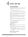
ECLIPSE E-QUE CARD . . . . . . . . . . . . . . . . . . . . . . . . . . . . . . . . . 4-1
E-QUE Card Description . . . . . . . . . . . . . . . . . . . . . . . . . . . . . . . . . . . . . . . 4-1
E-QUE Card Front-Panel Lights . . . . . . . . . . . . . . . . . . . . . . . . . . . . . . . . 4-1
ii
ECLIPSE OMEGA MATRIX INSTRUCTION MANUAL
Reset Button . . . . . . . . . . . . . . . . . . . . . . . . . . . . . . . . . . . . . . . . . . . . . 4-1
Power Supply & Status Lights . . . . . . . . . . . . . . . . . . . . . . . . . . . . . . . . 4-1
Status Lights . . . . . . . . . . . . . . . . . . . . . . . . . . . . . . . . . . . . . . . . . . . . . 4-4
LAN Data Light . . . . . . . . . . . . . . . . . . . . . . . . . . . . . . . . . . . . . . . . . . 4-4
LAN Link Light. . . . . . . . . . . . . . . . . . . . . . . . . . . . . . . . . . . . . . . . . . . 4-4
E-QUE Card REAR CoNNECTIONS. . . . . . . . . . . . . . . . . . . . . . . . . . . 4-4
E-Que Card Applications . . . . . . . . . . . . . . . . . . . . . . . . . . . . . . . . . . . . . . . 4-6
FreeSpeak/CellCom Application . . . . . . . . . . . . . . . . . . . . . . . . . . . . . . . . 4-6
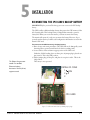
INSTALLATION. . . . . . . . . . . . . . . . . . . . . . . . . . . . . . . . . . . . . . 5-1
Reconnecting the CPU Card’s Backup Battery . . . . . . . . . . . . . . . . . . . . . . . 5-1
Verifying the Shipment . . . . . . . . . . . . . . . . . . . . . . . . . . . . . . . . . . . . . . . . . 5-2
Unpacking the System . . . . . . . . . . . . . . . . . . . . . . . . . . . . . . . . . . . . . . . . . . 5-2
Installing the Eclipse Omega Matrix . . . . . . . . . . . . . . . . . . . . . . . . . . . . . . . 5-3
Installing Power Supplies . . . . . . . . . . . . . . . . . . . . . . . . . . . . . . . . . . . . . . . . 5-3
Installing the Rear RJ-45 Connector Panels . . . . . . . . . . . . . . . . . . . . . . . . . . 5-3
Installing Rear RJ-45 Connector Panels in the Field . . . . . . . . . . . . . . . . . . . 5-3
Installing CPU Cards . . . . . . . . . . . . . . . . . . . . . . . . . . . . . . . . . . . . . . . . . . 5-4
Hot Patching . . . . . . . . . . . . . . . . . . . . . . . . . . . . . . . . . . . . . . . . . . . . . . . 5-4
Verifying the CPU Card Installation . . . . . . . . . . . . . . . . . . . . . . . . . . . . . 5-5
Installing Port and Expansion Cards . . . . . . . . . . . . . . . . . . . . . . . . . . . . . . . 5-5
Static Sensitivity . . . . . . . . . . . . . . . . . . . . . . . . . . . . . . . . . . . . . . . . . . . . 5-5
Hot Patching . . . . . . . . . . . . . . . . . . . . . . . . . . . . . . . . . . . . . . . . . . . . . . . 5-5
Slot Numbering. . . . . . . . . . . . . . . . . . . . . . . . . . . . . . . . . . . . . . . . . . . . . 5-6
Configuration . . . . . . . . . . . . . . . . . . . . . . . . . . . . . . . . . . . . . . . . . . . . . . 5-6
Verifying Port Card Installation . . . . . . . . . . . . . . . . . . . . . . . . . . . . . . . . . 5-6
Wiring Audio Devices to the Matrix . . . . . . . . . . . . . . . . . . . . . . . . . . . . . . . 5-6
Wiring Panels to the Matrix . . . . . . . . . . . . . . . . . . . . . . . . . . . . . . . . . . . 5-7
4-Pair Analog. . . . . . . . . . . . . . . . . . . . . . . . . . . . . . . . . . . . . . . . . . . . . 5-7
Single-Pair Digital . . . . . . . . . . . . . . . . . . . . . . . . . . . . . . . . . . . . . . . . . 5-8
Wiring CPU Card Interfaces . . . . . . . . . . . . . . . . . . . . . . . . . . . . . . . . . . . . . 5-8
GPI/RLY Interface Connector . . . . . . . . . . . . . . . . . . . . . . . . . . . . . . . . . . 5-9
RS-232 DB-9 Connector . . . . . . . . . . . . . . . . . . . . . . . . . . . . . . . . . . . . . 5-9
Alarm I/O Connector . . . . . . . . . . . . . . . . . . . . . . . . . . . . . . . . . . . . . . . 5-10
General-Purpose Outputs Connector (GP OUT) . . . . . . . . . . . . . . . . . . 5-12
General-Purpose Inputs Connector (GP IN) . . . . . . . . . . . . . . . . . . . . . . 5-13
Local Area Network Connectors (LAN1 and LAN2) . . . . . . . . . . . . . . . . 5-16
MAINTENANCE . . . . . . . . . . . . . . . . . . . . . . . . . . . . . . . . . . . . . 6-1
Introduction . . . . . . . . . . . . . . . . . . . . . . . . . . . . . . . . . . . . . . . . . . . . . . . . . 6-1
Routine Maintenance Recommendations . . . . . . . . . . . . . . . . . . . . . . . . . . . 6-1
Maintaining the Matrix . . . . . . . . . . . . . . . . . . . . . . . . . . . . . . . . . . . . . . . 6-1
Recommended Spare Parts. . . . . . . . . . . . . . . . . . . . . . . . . . . . . . . . . . . . . 6-1
Fail-Safe Modes . . . . . . . . . . . . . . . . . . . . . . . . . . . . . . . . . . . . . . . . . . . . . . . 6-1
Dual, Independent Power Supplies . . . . . . . . . . . . . . . . . . . . . . . . . . . . . . 6-2
Power Supply Alarm Output . . . . . . . . . . . . . . . . . . . . . . . . . . . . . . . . . . . 6-2
“Hot Patchability” . . . . . . . . . . . . . . . . . . . . . . . . . . . . . . . . . . . . . . . . . . . 6-2
Onboard Processors . . . . . . . . . . . . . . . . . . . . . . . . . . . . . . . . . . . . . . . . . . 6-2
Fail-Safe Communication . . . . . . . . . . . . . . . . . . . . . . . . . . . . . . . . . . . . . 6-2
ECLIPSE OMEGA MATRIX INSTRUCTION MANUAL
iii
Troubleshooting . . . . . . . . . . . . . . . . . . . . . . . . . . . . . . . . . . . . . . . . . . . . . . 6-2
Troubleshooting Power-Supply Problems. . . . . . . . . . . . . . . . . . . . . . . . . . 6-3
General Principles . . . . . . . . . . . . . . . . . . . . . . . . . . . . . . . . . . . . . . . . . 6-3
Specific Troubleshooting Examples . . . . . . . . . . . . . . . . . . . . . . . . . . . . 6-4
Troubleshooting Data Problems. . . . . . . . . . . . . . . . . . . . . . . . . . . . . . . . . 6-6
General Principles . . . . . . . . . . . . . . . . . . . . . . . . . . . . . . . . . . . . . . . . . 6-6
Specific Troubleshooting Examples . . . . . . . . . . . . . . . . . . . . . . . . . . . . 6-7
System Block Diagram. . . . . . . . . . . . . . . . . . . . . . . . . . . . . . . . . . . . . . . . . . 6-7
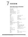
SPECIFICATIONS. . . . . . . . . . . . . . . . . . . . . . . . . . . . . . . . . . . . . 7-1
Omega Matrix Technical Specifications . . . . . . . . . . . . . . . . . . . . . . . . . . . . . 7-1
GLOSSARY . . . . . . . . . . . . . . . . . . . . . . . . . . . . . . . . . . . . . . . . 8-1
LIMITED WARRANTY . . . . . . . . . . . . . . . . . . . . . . . . . . . . . . . . . . . 9-I
Warranty Period. . . . . . . . . . . . . . . . . . . . . . . . . . . . . . . . . . . . . . . . . . . . . . . 9-i
Technical Support . . . . . . . . . . . . . . . . . . . . . . . . . . . . . . . . . . . . . . . . . . . . . 9-i
Warranty Repairs and Returns . . . . . . . . . . . . . . . . . . . . . . . . . . . . . . . . . . . . 9-ii
Non-Warranty Repairs and Returns. . . . . . . . . . . . . . . . . . . . . . . . . . . . . . . . 9-ii
Extended Warranty . . . . . . . . . . . . . . . . . . . . . . . . . . . . . . . . . . . . . . . . . . . . 9-ii
Liability . . . . . . . . . . . . . . . . . . . . . . . . . . . . . . . . . . . . . . . . . . . . . . . . . . . . 9-iii
iv
ECLIPSE OMEGA MATRIX INSTRUCTION MANUAL
FIGURES
The Eclipse Omega Matrix Assembly ............................................................ 1-2
Front Panel of Eclipse Omega Matrix ........................................................... 2-1
CPU Card’s Front Panel Lights and Controls ............................................... 2-4
Port Card’s Lights and Controls .................................................................... 2-8
Power supply module’s front door .............................................................. 2-11
The Eclipse houses three types of rear-connector panels .............................. 2-15
CPU Card’s Rear-Connector Panel ............................................................. 2-16
Front Fiber Card ........................................................................................... 3-3
Rear Fiber Card ............................................................................................ 3-5
Ring Topology Single Card Set Redundancy ................................................ 3-7
Ring Topology Dual Card Set Redundancy ................................................ 3-10
Front E-Que Card ........................................................................................ 4-3
Rear E-Que Card .......................................................................................... 4-5
E-Que Card Antenna Connection ................................................................ 4-7
E-Que Card Splitter Connection .................................................................. 4-8
Multiple Matrices with DECT Sync Interconnect ........................................ 4-9
CPU card with detail of CON9 jumper plugs ............................................... 5-1
Wiring from the Matrix to an Analog Panel Using RJ-45 ............................. 5-7
Wiring from the Matrix to a Digital Panel Using RJ-45 ................................ 5-8
CPU Card Interface Connectors ................................................................... 5-9
Wiring the Matrix DB-9M to a DB-9F Computer Serial Port Connector ... 5-10
Wiring the Matrix DB-9M to a DB-25F Computer Serial Port Connector . 5-10
Wiring the Alarm I/O Connector to an Alarm Relay Connector ................. 5-11
Eclipse Omega Matrix’s Double-Pole Double-Throw Alarm Relay ............. 5-12
Pin Configuration of the General-Purpose Outputs Connector .................. 5-13
Opto-Isolated Connection to Eclipse Omega GPI Connector ..................... 5-14
Non-Isolated Connection to Eclipse Omega GPI Connector ...................... 5-14
Pin Assignments for Eclipse Omega General-Purpose Inputs Connector .... 5-15
Pin Assignments for LAN1 and LAN2 Connectors ..................................... 5-16
System Block Diagram .................................................................................. 6-7
ECLIPSE OMEGA MATRIX INSTRUCTION MANUAL
i
ii
ECLIPSE OMEGA MATRIX INSTRUCTION MANUAL
IMPORTANT SAFETY INSTRUCTIONS
Please read and follow these instructions before operating an Eclipse Omega matrix
system. Keep these instructions for future reference.
(1) WARNING: To reduce the risk of fire or electric shock, do not expose this
apparatus to rain or moisture.
(2) Do not use the apparatus near water.
(3) Clean only with a dry cloth.
Please read and follow these
instructions before operating
an Eclipse Omega matrix
system.
(4) Do not block any ventilation openings. Install in accordance with the
manufacturer’s instructions. Install the Eclipse Omega matrix system according
to the directions in the Installation Chapter of this manual.
(5) Do not install near any heat sources such as radiators, heat registers, stoves, or
other apparatus (including amplifiers) that produce heat. Do not place naked
flame sources such as candles on or near the matrix.
(6) Do not defeat the safety purpose of the polarized plug or grounding-type
plug. A polarized plug has two blades with one wider than the other. A
grounding-type plug has two blades and a third grounding prong. The wide
blade or the third prong are provided for your safety. If the provided plug does
not fit into your outlet, consult an electrician for replacement of the obsolete
outlet.
(7) Protect power leads from being walked on or pinched particularly at plugs, at
convenience receptacles, and at the point where they exit from the apparatus.
Note: A “convenience receptacle” is an extra AC power outlet located on the back
of a piece of equipment, intended to allow you to power other equipment.
(8) Only use attachments/accessories specified by the manufacturer.
(9) Use only with the cart, stand, tripod, bracket, or table specified by the
manufacturer, or sold with the apparatus. When a cart is used, use caution when
moving the cart/apparatus combination to avoid injury from tip-over.
(10) Unplug the apparatus during lightning storms or when unused for long
periods of time.
(11) Refer all servicing to qualified service personnel. Servicing is required when
the apparatus has been damaged in any way, such as a power-supply cord or plug
is damaged, liquid has been spilled or objects have fallen into the apparatus, the
apparatus has been exposed to rain or moisture, does not operate normally, or has
been dropped.
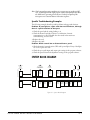
Please familiarize yourself with the safety symbols in Figure 1. When you see
these symbols on an Eclipse Omega matrix system, they warn you of the
potential danger of electric shock if the system is used improperly. They also refer
you to important operating and maintenance instructions in the manual.
ECLIPSE OMEGA MATRIX INSTRUCTION MANUAL
iii
CAUTION
RISK OF ELECTRIC SHOCK
DO NOT OPEN
This symbol alerts you to the presence of uninsulated dangerous
voltage within the product’s enclosure that might be of sufficient
magnitude to constitute a risk of electric shock. Do not open
the product’s case.
This symbol informs you that important operating and maintenance instructions are included in the literature accompanying
this product.
Figure 1: Safety Symbols
EMC AND SAFETY
The Eclipse Omega matrix meets all relevant CE, FCC, UL, and CSA
specifications set out below:
EN55103-1 Electromagnetic compatibility. Product family standard for audio,
video, audio-visual, and entertainment lighting control apparatus for
professional use. Part 1: Emissions.
EN55103-2 Electromagnetic compatibility. Product family standard for audio,
video, audio-visual, and entertainment lighting control apparatus for
professional use. Part 2: Immunity.
UL 60065-7, CAN/CSA-C22.2 No.60065-3, IEC 60065-7 Safety requirements.
And thereby compliance with the requirement of Electromagnetic
Compatibility Directive 2004/108/EC and Low Voltage Directive 2006/95/EC
This device complies with Part 15 of the FCC Rules. Operation is subject to
the following two conditions: (1) this device may not cause harmful
interference, and (2) this device must accept any interference received,
including interference that may cause undesired operation.
iv
ECLIPSE OMEGA MATRIX INSTRUCTION MANUAL
1
THE ECLIPSE OMEGA MATRIX
SYSTEM: AN OVERVIEW
The Eclipse range of matrices comes in three frame formats. The Eclipse Omega
matrix is the largest with 15 client card slots providing up to 240 ports in six rack
units (6RU). The other members of the Eclipse family are the Median, with slots
for up to 7 client cards and 8 interface modules in six rack units (6RU), and the
PiCo, with up to 36 panel and 4-wire ports in one rack unit (1RU).
The Eclipse Omega matrix
houses up to 240 ports and
dual redundant power
supplies in a six rack unit
chassis.
Clear-Com designed the Eclipse Omega matrix with modular components that
help you to plan, build, or customize your communication system to meet the
most rigorous demands of modern broadcast, performing arts, industrial,
aerospace, and military environments.
FEATURES
Features of the Eclipse Omega matrix system include:
• Full audio bandwidth throughout the signal chain, producing superior
broadcast audio quality. The system maintains 24-bit sampling and 30 Hz to
22 kHz frequency response.
• A six rack-unit matrix housing up to 240 RJ-45 ports and dual redundant
power supplies.
• Fifteen available port cards supporting 16 ports each.
• Fail-safe redundancy achieved by two processor cards and two power supplies.
• Power supplies that automatically switch to the correct voltage, for
compatibility around the world.
• Eight general purpose inputs and eight relays, located directly on the matrix.
• Full compatibility with selected Matrix Plus 3 panels and interfaces, selected
4000 Series II panels, V-Series panels and FreeSpeak/CellCom antennas and
splitters.
• Matrices that link across cities, nations, or continents through trunk lines and
fiber.
• Uses the same fiber-networking cards as the Eclipse Median matrix.
• Connection to FreeSpeak/CellCom antennas and splitters using the E-Que
card.
• Multiple E-Que cards can be fitted to a single matrix.
• VOX-programmable audio which visually cues you at the matrix when audio
transmits at a programmed threshold on a connected intercom panel or
interface.
ECLIPSE OMEGA MATRIX INSTRUCTION MANUAL
1-1
• “Virtual” operation in which a complete networked system can be operated
and maintained from anywhere in the world. The system provides both local
area network and Internet access to the central matrix.
• Visual and intuitive Eclipse Configuration System (ECS) programming
software.
THE ECLIPSE OMEGA MATRIX
A complete Eclipse Omega system consists of a central matrix and the remote
audio devices—intercom panels, interfaces, 4-wire equipment—connected to it.
Each element of the Eclipse Omega system is briefly described in this chapter and
more fully described later in this manual and in the Eclipse set of manuals.
The Eclipse set of manuals includes individual manuals on each matrix, panel,
and interface in the system, as well as Installing the Eclipse System: An Overview.
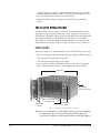
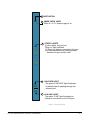
MATRIX ASSEMBLY
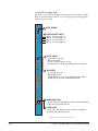
As shown in Figure 1, the matrix assembly consists of the following components:
• The metal housing for the circuit cards and power supplies, called the “matrix”
• The removable and replaceable circuit cards
• The removable and replaceable power supplies
• The rear panel connectors which link the circuit cards to devices and media
such as intercom panels, interfaces, wireless equipment and optical fiber.
Eclipse Frame
RJ-45 Connectors
("Ports") on Back Panel
Thirteen 16-Port Circuit Cards
Two Expansion Cards
Dual Redundant
CPU Cards
Dual Redundant
Power Supplies
Figure 1-1: The Eclipse Omega Matrix Assembly
Note: The term “central matrix” is used to differentiate the system’s core hardware
and software from the connected intercom panels and interfaces. The
central matrix itself consists of the matrix hardware and the ECS software.
1-2
ECLIPSE OMEGA MATRIX INSTRUCTION MANUAL
MATRIX CHASSIS
The matrix chassis is a metal rectangular box which measures six rack units high
and 19-inches wide (26.9 cm x 48.3 cm). It has slots for 17 circuit cards and 2
power supplies.
RJ-45 and fiber-optic connectors are located on removable plates on the rear of
the chassis. These connect the circuit cards to intercom devices and media such
as panels, interfaces, 4-wire audio equipment, wireless equipment and fiber-optic
cables.
CIRCUIT CARDS
The matrix holds two types of circuit cards: system cards and port cards. The
cards slide vertically into the front of the matrix and connect to the matrix’s
backplane.
CPU Card
The CPU card is the master configuration card in the Eclipse Omega system. It
provides the serial data and Ethernet connection to the connected PC computer.
The CPU card also coordinates the data flow between the other cards in the
system, allowing them to communicate with each other. The computer memory
chip which stores four complete system configurations is located on the CPU
card, so that a selected configuration can be retrieved and activated directly from
the card.
Like the other cards in the system, the CPU card fits in the Eclipse Omega
matrix. The card fits vertically in a six rack unit (6 RU) space and connects to the
matrix’s backplane.
One CPU card is required for each Eclipse Omega system. Two cards can be
installed to provide redundancy in the case of outages or repair needs.
Port Card
A port card controls the operation of panels and interfaces connected to it. Panels
and interfaces connect to the port card through an RJ-45 connector, or “port,”
on the matrix’s rear panel. Shielded category-5 cable attaches the panel or
interface to the RJ-45 connector.
The MVX-A16 analog port card sends balanced audio and RS-422 data signals
to connected audio equipment through 4-pair shielded category-5 cable. The
card connects up to 16 audio devices—such as intercom panels, interfaces, or
4-wire audio equipment—to the central matrix. Each audio device connected to
a port card communicates with all other audio devices in the system and with the
central matrix.
For intelligent linking, shielded category-5 cable is run from a port on one
Eclipse Omega matrix to a port on a second Eclipse Omega matrix to form a
trunkline connection.
ECLIPSE OMEGA MATRIX INSTRUCTION MANUAL
1-3
Fiber Card
Fiber cards connect Eclipse matrices together to provide a high speed, dual
redundant link to transfer audio samples and data between systems. These
connections can be configured in various ways to provide protection against the
loss of a link or a node.
Each fiber card link consists of a front card with various status indicators and a
rear card with two Duplex LC Terminated fiber optic connectors (TXVRA and
TXVRB).
E-Que Card
The E-QUE cards allows the Eclipse matrix to connect to FreeSpeak/CellCom
antennas and FreeSpeak/CellCom antenna splitters. Each E-Que card set
consists of a front card with a reset button and various status indicators, and a
rear card with eleven RJ45 ports giving eight standard ports, DECT sync in and
out and a LAN port for diagnostic use.
Each E-Que front card has status LEDs for power, port activity and LAN status.
The port activity LEDs indicate whether there is a device connected to an E1
port and that a connection has been established between this port and the
connected device.
The E-Que cards must be fitted in the rightmost available slots (furthest away
from the CPU cards) on the Omega and up to four E-Que cards can be fitted on
a matrix.
POWER SUPPLIES
Eclipse Omega matrix has two Euro Cassette power supply units that you can
easily install or remove as needed. One power supply unit can power an entire
matrix; the second unit provides a backup in case of failure or damage to the first
unit.
In addition, the two supplies have separate IEC connectors to AC mains, and are
designed for completely automatic and transparent changeover between supplies
in the event of a power outage in one of the AC mains circuits.
An over-temperature sensor is connected to both an audible failure alarm and a
warning light, allowing you to diagnose and correct any power anomalies while
the system remains operational.
MVX REAR-PANEL CONNECTORS (“PORTS”)
The matrix’s rear-panel RJ-45 connectors are called “ports.” You connect shielded
category-5 cable to a “port” to carry signals from the Eclipse Omega circuit cards
to connected intercom panels or interfaces.
ECLIPSE CONFIGURATION SYSTEM (ECS)
The Eclipse Configuration System (ECS) controls the operation of the remotely
connected audio devices by sending signals to the circuit cards in the matrix,
which then relay the signals to the audio devices.
1-4
ECLIPSE OMEGA MATRIX INSTRUCTION MANUAL
“Configurations”—which are the operating parameters of complete system
setups, can be created from the connected computer. You can store four complete
system configurations in the computer’s memory to retrieve and activate when
needed.
The Eclipse Configuration System runs on three versions of Windows: Windows
XP, Windows Server 2003 and Windows 2000. When running ECS on the
three Windows operating systems, the client and server can run on separate
machines connected over a network.
From the Eclipse Configuration Software, you can create point-to-point and
fixed group or party-line communications among the connected audio devices,
assign a “label” to each port/panel, and inhibit or enable features at any
connected panel. You can set up the system to run on a client/server model over a
network, allowing you to control the matrix remotely.
INTERCOM PANELS AND ACCESSORY PANELS
All intercom panels connect to the central matrix via shielded category-5 cable
terminated with RJ-45 connectors. The shielded category-5 cable connects to the
matrix through the MVX-A16 analog circuit card. The following Clear-Com
intercom panels are compatible with the Eclipse Omega matrix system:
• i-Station family, including expansion panels
• ICS-2003 intercom panels, including expansion panels
• ICS-52 and ICS-92 intercom panels, including expansion panels
• ICS-62 and ICS-102 intercom panels, including expansion panels
• ICS-1008 and ICS-1016 intercom panels, including expansion panels
• 4215E, 4224E, 4226E, 4294E, 4212E, 4222E, 4203E, 4206E, 4230E and
4230VE 4000 Series II panels
• V12LD, V24LD, V12PD, V24PD, V12LDD, V12LDE and V12PDE
V-Series panels
Each of these panels is described in its own manual. For a full description of the
operation, installation, and maintenance of a panel, refer to the appropriate panel
instruction manual.
INTERFACES
Interface modules convert the 4-wire signals of a central matrix port to other
types of signals that communicate with devices such as telephones, camera
intercoms, two-way radios, and so on. In this way non-4-wire devices can
communicate with the central matrix.
Each interface module has hardware connectors to connect to both the central
matrix and to the external device that communicates with the central matrix.
Most interface modules connect to the central matrix via shielded category-5
cable terminated with RJ-45 connectors. The DIG-2 digital interface module,
however, connects to the central matrix via double-shielded 24 AWG conductor
category-6 enhanced (CAT-6E) STP cable.
ECLIPSE OMEGA MATRIX INSTRUCTION MANUAL
1-5
The type of cable used to connect the interface module to the non-4-wire device
varies with the device. Each of these connections is described more fully in the
individual manual for each interface.
The following interface modules are compatible with the Eclipse Omega matrix:
• TEL-14 telephone interface module
• CCI-22 dual party-line interface module
• FOR-22 four-wire interface module
• GPI-6 general purpose inputs interface module
• RLY-6 relay (general-purpose outputs) interface module
• AES-6 digital interface module
• DIG-2 digital interface module (transparent to the system, configured in ECS
as the type of panel it is connected to)
Each of these interfaces is described in its own manual. For a full description of
the operation, installation, and maintenance of an interface, refer to the
individual manual for that interface.
1-6
ECLIPSE OMEGA MATRIX INSTRUCTION MANUAL
2
OPERATION
THE ECLIPSE OMEGA MATRIX AND CIRCUIT CARDS
The Eclipse Omega matrix chassis houses the circuit cards, power supplies, and
connectors that form the central hardware of the system. Measuring 19-inches
wide and 6 rack units high (48.3 cm x 26.9 cm), the matrix chassis installs in a
standard equipment rack.
Various types of Eclipse Omega circuit cards perform unique functions. System
cards control overall system operation, port cards control the operation of
connected panels and interfaces and communications cards allow
communication with wireless equipment and fiber optic links.
Two Euro Cassette power supplies provide fail-safe redundancy in the event of a
component failure or an AC circuit outage. Front-panel lights give you
information about the condition of the power supplies, allowing you to take
preventative corrective action.
Each MVX circuit card connects to an individual panel on the back of the
Eclipse Omega matrix. This panel holds the RJ-45 sockets for connecting cable
to intercom panels and interfaces.
The Eclipse Omega matrix is completely modular, allowing you to add or remove
cards, power supplies, and connector panels to meet the operational needs of
your environment.
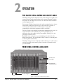
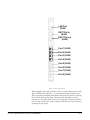
FRONT-PANEL CONTROLS AND LIGHTS
Two Euro Cassette
Power Supplies
Power Supply Lights
and Alarm Reset Button
CPU Cards
P1 & P2
Port Cards 1 through 15
Figure 2-1: Front Panel of Eclipse Omega Matrix
ECLIPSE OMEGA MATRIX INSTRUCTION MANUAL
2-1
CENTRAL PROCESSOR UNIT (CPU) CARD DESCRIPTION
The central processor unit (CPU) card holds the circuitry that allows the system
to connect to, and communicate with, the following interfaces:
• A computer
• External alarms
• Eight general-purpose inputs (GPIs)
Note: General Purpose
Outputs are also
referred to as “relays.”
• Eight general-purpose outputs (GPOs)
• Two separate local area network (LAN) connections for Ethernet-based
communication with a network
• An external interface that provides additional GPIs and GPOs
In addition, the card’s operational memory holds four complete preassigned
system configurations to access and activate either directly from the CPU card or
from the ECS configuration software.
CREATING AND STORING SYSTEM CONFIGURATIONS
A “configuration” is a complete set of operating parameters for the system which
includes talk and listen paths for each connected intercom panel. Depending on
the interfaces installed, the configuration can also include more sophisticated
features such as paging, call signaling, interrupt foldback (IFB), ISO, groups,
automatic DTMF dialing, routing, and many other features.
Note: If the
configuration does not
remain in memory after
you power off, please
see the first section in
Chapter 3,
“Reconnecting the CPU
Card’s Backup Battery.”
When you connect an external computer to the matrix, you can retrieve the
current configuration information stored in the CPU microprocessor’s memory
(using the Eclipse Configuration Software) and display the configuration on the
computer’s screen.
You can then apply the current configuration, modify it, or create a new
configuration with the Eclipse Configuration Software. If you create more than
one configuration, you can store unused configurations on your computer’s hard
disk or on CD-ROM to use later, allowing you to instantly reconfigure your
system as often as you require.
The CPU card itself will store up to four complete configurations in its
operational memory that you can apply either directly from the CPU card or
from the connected computer.
SETTING THE DEFAULT IP ADDRESS
The CPU card LAN ports can be reset to their default IP addresses by pressing
and holding the ‘ENG’ and ‘FULL RESET’ buttons on the CPU front card and
then pressing the ‘RESET’ button at the top and then holding the ‘ENG’ and
‘FULL RESET’ buttons until the card resets. This will reset the LAN1 ethernet
port to the factory default address of 172.16.2.100 and all other ethernet ports to
the 0.0.0.0 (blank) address.
2-2
ECLIPSE OMEGA MATRIX INSTRUCTION MANUAL
FAIL-SAFE OPERATION
The CPU card’s non-volatile memory stores all information about the current
operating configuration and the three additional configurations, allowing the
system to restore itself automatically after a power failure, after replacement of a
port card, or after replacement of a panel.
An Eclipse Omega system will operate with either one or two CPU cards. When
you install a second card, that card stores the four configurations in its RAM as a
backup to the main card. If the main card is removed or becomes
non-operational for any reason, the system will automatically switch to the
second card as backup.
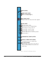
CPU CARD LIGHTS AND CONTROLS
The following sections describe the CPU card’s status lights and controls, which
are illustrated in Figure 2-2.
1 Reset Button
Pressing the reset button causes the CPU card to stop its current activity and to
restart. The same configuration that was active before you reset the system will be
active after you reset it.
During the reset, configuration information reloads to the card’s operational
memory from its non-volatile memory and the card starts running again from
the beginning.
Note: The reset button is slightly recessed from the front panel to prevent it from
being accidentally pressed. You need a tool, such as a bent paper clip, to
press this button.
2 Power Supply Lights
+ 5-Volt Light
When lit, the “+5V” light indicates that the matrix’s +5-volt power supply is
actively supplying power to the CPU card.
+3.3-Volt Light
When lit, the “+3.3V” light indicates that the matrix’s +3.3-volt power supply is
actively supplying power to the CPU card.
3 Dot Matrix Lights
The rectangular array of lights just below the power-supply lights displays a
number (either 1, 2, 3, or 4) to indicate the currently selected configuration. The
Eclipse Configuration System (ECS) controls these lights.
ECLIPSE OMEGA MATRIX INSTRUCTION MANUAL
2-3
1 RESET BUTTON
RESET
+5V
+3.3V
2 POWER SUPPLY LIGHTS
When lit, +5-volt power supply is on
When lit, +3.3-volt power supply is on
3 DOT MATRIX LIGHTS
Displays the number of the currently selected software configuration
OK
IPC
MASTER
LAN A
LAN B
IN SYNC
SI
4 STATUS LIGHTS
When flashing, software is running
Blinks when two CPU cards are exchanging information
When lit, this CPU card is acting as master card
Blinks when LAN A is connected and running
Blinks when LAN B is connected and running
Blinks when multiple matrices are connected and synchronized
Reserved for future use
5 CONFIGURATION ("CONFIG") BUTTON
CONFIG
ENG
FULL
RESET
6 DEFAULT IP ADDRESS RESET BUTTON
Press with full reset and reset to set default IP address
7 FULL RESET BUTTON
When held through a reset cycle, results in a full system reset.
When pressed with the ENG button and reset button sets the
default IP address
Figure 2-2: CPU Card’s Front Panel Lights and Controls
2-4
ECLIPSE OMEGA MATRIX INSTRUCTION MANUAL
4 Status Lights
OK Light
When flashing, the “OK” light indicates that the CPU card is successfully
communicating with the Eclipse Configuration System (ECS).
IPC (Interprocessor Communication) Light
The “interprocessor communication” (IPC) light only operates when there are
two CPU cards in the matrix. When lit, the light indicates that the two CPU
cards are exchanging information.
Master Light
An Eclipse Omega system can have two CPU cards, although the system will
operate with only one. If the primary card becomes unavailable for any reason,
the second card can serve as backup while the primary card is repaired or
replaced.
The “master” light illuminates on whichever CPU card is currently serving as
master. If there is a backup CPU card in the matrix, its “master” light will not
illuminate if the primary card is acting as master.
LAN A Light
When you connect a local area network (LAN) to the matrix’s “LAN A” port, the
CPU card’s “LAN A” LED lights to indicate a connection to the Eclipse
Configuration System LAN A.
LAN B Light
When you connect a second local area network to the matrix’s “LAN B” port, the
CPU card’s “LAN B” LED lights to indicate a connection to the Eclipse
Configuration System (ECS) LAN B.
Sync Light
When you connect multiple Eclipse matrices together, the “sync” light
illuminates to indicate that the matrices are connected and synchronized.
SI Light
The “SI” light flashes to indicate communications activity.
5 Configuration “CONFIG” Button
The CPU card can hold four complete system configurations in its operational
memory. When you tap the “CONFIG” button, the number of the currently
active configuration (either 1, 2, 3, or 4) appears in the dot-matrix display.
Each time you subsequently tap the button, the next configuration number in
the series appears in the dot-matrix display. The numbers cycle forward until all
of the choices have been displayed, then start again at “1.”
ECLIPSE OMEGA MATRIX INSTRUCTION MANUAL
2-5
When a non-active configuration’s number appears in the display, it flashes to
indicate its non-active status. When an active configuration’s number (either 1,2,
3, or 4) appears in the display, it illuminates solidly (without flashing) to indicate
that it is the active configuration.
To select one of the four configurations from the CPU card:
1. Repeatedly press the CONFIG button until the desired configuration’s
number (1,2,3, or 4) appears in the display.
2. When the desired number appears, press and hold the CONFIG button until
the display stops flashing. This should take about three seconds.
The selected configuration then becomes the system’s active operational
configuration.
6 Engineering “ENG” Button
This button is used to reset the system to the default IP addresses.
7 Full Reset Button
When you perform a full reset, all cards in the matrix reset regardless of any
system preferences in the program software and non-volatile memory is cleared.
To perform a full reset:
1. Press and hold the card’s lower RESET button (the “full reset” button).
2. Simultaneously press and release the card’s upper RESET button.
3. Continue holding the card’s lower RESET button for two seconds.
The card performs a full reset.
The same configuration that was active before you reset the system will be active
after you reset it.
When the cards and connected audio devices reset, they momentarily stop their
current activity and restart. During this process configuration information is
downloaded to the cards and audio devices from the CPU card’s non-volatile
RAM.
Note: Under normal operating conditions it is not necessary to perform a full
reset. Technical personnel might perform a full reset if they believe that the
CPU card is operating incorrectly as a result of corruption of the
microprocessor’s internal data or instruction sequence.
2-6
ECLIPSE OMEGA MATRIX INSTRUCTION MANUAL
PORT CARD DESCRIPTION
Port cards connect the central matrix to intercom panels and interfaces. In a
linked system, port cards connect trunk lines. The analog card, designated the
“MVX-A16,” supports normal audio feeds, user panels, and trunk lines.
All cards contain a voice detection mechanism (“VOX”) that you program from
the ECS configuration software. VOX detection allows you to know when the
audio on a particular channel has exceeded a threshold. This is particularly useful
for channels that are inactive periodically, so that you are visually cued when
audio appears on the line.
Each port card has two system status lights. A port card’s FRAME DATA light
illuminates to indicate the card’s successful communication with the CPU card.
A port card’s STATUS light illuminates to indicate a failure in communication
between the port card and the CPU card. When all port cards are lined up in the
matrix, the system status lights form a horizontal row showing the overall state of
the system.
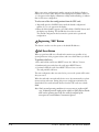
PORT CARD FRONT-PANEL LIGHTS AND CONTROLS
1 Reset Button
Pressing the reset button causes the card and all connected audio devices to
momentarily stop their current activity and to restart. The card’s “frame data”
light goes off when the reset starts and comes back on when the reset is complete.
During the reset, configuration information downloads to the card and its
connected audio devices from the CPU card. If the entire system is operating
except for one port card, or one or more panels connected to the card, press the
reset button for that card only.
Note: The reset button is slightly recessed from the front panel to prevent it from
being accidentally pressed. You need a tool, such as a bent paper clip, to
press this button.
2 Power Supply Lights
+12-Volt and -12-Volt Power Supply Lights
The matrix’s +12-volt and -12-volt power supplies provide electric current to
these two green lights. When lit, these lights indicate that the matrix’s +12-volt
and -12-volt power supplies are present and supplying electric current to the
card.
+5-Volt Power Supply Light
The matrix’s +5-volt power supply provides electric current to this green light.
When lit, the light indicates that the +5 supply is present and supplying electric
current to the card.
ECLIPSE OMEGA MATRIX INSTRUCTION MANUAL
2-7
+3.3-Volt Power Supply Light
The matrix’s +3.3-volt power supply provides electric current to this green light.
When lit, the light indicates that the +3.3-volt supply is present and supplying
electric current to the card.
1 RESET BUTTON
RESET
+12V
-12V
+5V
+3.3V
ACTIVE VOX
1
2
2 POWER SUPPLY LIGHTS
When lit, +12 V power supply is on
When lit, –12 V power supply is on
When lit, +5 V power supply is on
When lit, +3.3 V power supply is on
3 ACTIVE LIGHTS
16 yellow lights, one per port
When on, light indicates:
(1) There is a device connected to the port.
(2) Communications are running properly between the port and the card.
3
4
5
6
7
8
4 VOX LIGHTS
16 green lights, one per port
When on, light indicates:
(1) A VOX threshold for the port is programmed in the system software.
(2) Audio input on the port has exceeded the VOX threshold.
9
10
11
12
13
14
15
16
Frame Status
Data
5 FRAME DATA LIGHT
The green "frame data" light illuminates to indicate successful communication
between the port card and the CPU card.
6 STATUS LIGHT
The red "status" light illuminates to indicate a failure in communication
between the port card and the CPU card.
Figure 2-3: Port Card’s Lights and Controls
2-8
ECLIPSE OMEGA MATRIX INSTRUCTION MANUAL
3 Active Lights
When lit, an “active” light indicates successful communication between the port
card and a connected device such as an intercom panel or interface.
Each of the port card’s 16 yellow “active” lights corresponds to one of 16
rear-panel connectors or “ports” to which audio devices can be connected.
4 VOX Lights
When lit, a “VOX” light indicates that the audio level on a connected device,
such as an intercom panel or interface, has exceeded a preset threshold. You set
the threshold audio level through the ECS configuration software.
Each of the port card’s 16 green “VOX” lights corresponds to one of 16
rear-panel connectors or “ports” to which audio devices (intercom panels or
interfaces) can be connected.
5 Frame Data Light
The green “frame data” light illuminates to indicate successful communication
between the port card and the CPU card.
6 Status Light
The red “status” light illuminates to indicate a failure in communication between
the port card and the CPU card.
ECLIPSE OMEGA MATRIX INSTRUCTION MANUAL
2-9
POWER SUPPLY DESCRIPTION
Eclipse Omega has two Euro Cassette power supply units that you can easily
install or remove as needed. One power supply unit can power an entire matrix;
the second unit provides a backup in case of an equipment failure.
In addition, the two supplies have separate IEC connectors to AC mains power,
and are designed for completely automatic and transparent changeover between
supplies in the event of an outage on one of the AC mains circuits. For this
feature to work, each power supply should be connected to a different AC mains
branch.
If the temperature inside the Eclipse matrix exceeds a threshold, both an audible
alarm and a warning light switch on, allowing you to diagnose and correct power
anomalies while the system remains in operation.
Each cassette has two status lights located on the power supply unit in the upper
left corner. The green light stays on continuously to let you know that the unit is
receiving appropriate power. The amber light goes on when a DC output or AC
input falls too low.
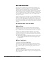
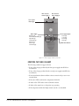
DIAGNOSING POWER SUPPLY PROBLEMS
Figure 2-4 illustrates the front panel alarm lights, power supply lights, and reset
button. An alarm source triggers the main alarm light and also one of the
additional six red alarm lights, allowing you to identify or correct alarm
conditions before they affect the operation of the matrix.
Each of the four green power supply lights stays on continuously to show that the
power supplies are receiving sufficient AC current. When one of these lights
switches off, the power supplies need to be replaced or repaired.
Under normal operating conditions, the red front-panel alarm lights stay off,
while the green power supply lights stay on continuously.
The power supplies may need to be adjusted if E-Que or fiber cards are installed.
For details of the adjustments please refer to the system upgrade manual.
2-10
ECLIPSE OMEGA MATRIX INSTRUCTION MANUAL
Euro Cassette
Power Supply 1
Euro Cassette
Power Supply 2
Euro Cassette
Alarm Lights
Alarm Lights
Main Alarm Light
External Alarm (EXT ALARM) Light
Temp Alarm Light
Fan-Fail Alarm Light
PSU1 Fail Light
PSU2 Fail Light
Fan-On Alarm Light
Power Supply LIghts
+12 Volt Light
+ 5 Volt Light
+3.3 Volt Light
--12 Volt Light
Alarm Reset Button
Figure 2-4: Power supply module’s front door
CONDITIONS THAT CAUSE AN ALARM
The following conditions trigger an alarm:
• If any of the voltages produced by the first power supply unit fall below
normal levels.
• If any of the voltages produced by the second power supply unit fall below
normal levels.
• If an internal matrix alarm condition activates a matrix relay to turn on an
external alarm.
• If the active CPU card exceeds a temperature threshold.
• If either of the CPU cards is removed from the matrix.
• If either of the matrix’s two cooling fans stop operating.
• If the temperature inside the Eclipse matrix exceeds a set threshold.
ECLIPSE OMEGA MATRIX INSTRUCTION MANUAL
2-11
MAIN ALARM LIGHT
An alarm condition triggers the following events:
• The red main alarm light flashes.
• The matrix’s internal alarm buzzer sounds.
• Any installed alarm relay outputs switch to active (the normally open contact
closes and the normally closed contact opens). When the alarm relay activates,
it can cause an externally connected device like a light or buzzer to switch on.
• One of the six auxiliary red alarm lights may go on to more precisely indicate
the source of the alarm condition. (These lights are discussed in further detail
later in this section.)
ALARM RESET BUTTON
When you press the alarm reset button, the following events take place, even if
the alarm condition has not been corrected:
• The internal audible alarm buzzer stops buzzing.
• Any wired relay contacts return to their inactive state. If these relays are
connected to external alarm lights or alarm buzzers, those lights or buzzers
shut off.
If the original alarm condition still exists, the red main alarm light on the matrix’s
front panel continues to flash. The red main alarm light only stops flashing when
all original sources triggering the alarm are corrected.
If a new alarm condition or conditions occur before the original alarm conditions
are corrected, the internal buzzer and relay contacts will not reactivate. They will
only reactivate after all original alarm conditions are corrected.
AUXILIARY ALARM LIGHTS
When an alarm condition occurs, any of the six auxiliary alarm lights may switch
on, in addition to the main alarm light, to help you diagnose the alarm
condition. The following sections describe the six auxiliary alarm lights.
External Alarm (“Ext Alarm”)
The “external” alarm (labelled “EXT ALARM”) light switches on to indicate that
an alarm condition has triggered the built-in relay outputs to turn on any
externally installed alarms such as lights or bells. You connect the external alarm
to the matrix through the 9-pin D-type connector on the matrix’s rear panel
labeled “Alarm I/O.”
Temp Alarm
The red “temp” alarm light switches on to indicate one or both of the following:
• The active CPU card has detected a temperature in the matrix above a
threshold.
2-12
ECLIPSE OMEGA MATRIX INSTRUCTION MANUAL
• One of two CPU cards has been removed from the matrix. (Note that this
feature only operates if there are two CPU cards installed in the matrix. If
there is only one CPU card, the Temp alarm light does not switch on if the
card is removed.)
Fan-Fail Alarm
The red fan-fail alarm light illuminates when either fan in the power-supply
module stops rotating correctly.
PSU1 Fail
When the first power supply unit is operating correctly, the red PSU1 light stays
off, while the four green power supply lights (+12V, +5V, +3.3V, -12V) stay on
continuously.
If a DC output or AC input to the first power supply drops too low, the red
PSU1 light switches on to warn you. (The amber light on the power supply unit
itself also switches on to indicate the same condition.) One of the green power
supply lights may then switch off to help indicate the source of the trouble.
Note that the PSU1 fail light only works if the first power supply is plugged into
the matrix’s midplane from inside the matrix.
Note: A temperature sensor inside the power supply senses if the power supply
overheats, and switches on the second matrix cooling fan. The red “Temp”
light switches on to indicate that the active CPU card, not a power supply,
has overheated.
PSU2 Fail
When the second power supply unit is operating correctly, the red PSU2 light is
off, while the four green power supply lights (+12V, +5V, +3.3V, -12V) are on
continuously.
When a DC output or AC input to the second power supply drops too low, the
red PSU2 light switches on to warn you. (The amber light on the power supply
unit itself also switches on to indicate the same condition.) One of the green
power supply lights may then switch off to help indicate the source of the
trouble.
Note that the PSU2 fail light only works if the second power supply is plugged
into the matrix’s midplane from inside the matrix.
Note: A temperature sensor inside the power supply senses if the power supply
overheats, and switches on the second matrix cooling fan. The red “Temp”
light switches on to indicate that the active CPU card, not a power supply,
has overheated.
ECLIPSE OMEGA MATRIX INSTRUCTION MANUAL
2-13
Fan-On Indicator
Two fans deliver forced air cooling to the matrix’s power supplies. The primary
fan runs continuously. If a temperature exceeding a threshold is detected in a
power supply and extra cooling is required, a second fan switches on to increase
the air flow. The “fan-on” alarm light illuminates red to indicate that the second
fan is on.
POWER SUPPLY LIGHTS
The green power-supply lights illuminate to indicate that the power supplies are
receiving +12 V, –12 V, +5 V, and 3.3 V power.
2-14
ECLIPSE OMEGA MATRIX INSTRUCTION MANUAL
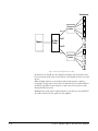
CONNECTING THE MATRIX
The Eclipse Omega matrix connects to devices such as the configuration
computer, panels, interfaces, and other matrices through its rear-panel hardware
connectors, often called “ports.” These connectors are housed in modular
removable panels. Each panel is associated with a corresponding front-panel
circuit card.
Port
Port
Port
Port
Blank Panels are installed
in unused portions of the
frame.
Port-Card Rear Panels have
16 RJ-45 connectors each,
to connect to intercom stations
and interfaces.
1-1
1-2
1-3
1-4
The CPU-Card Rear Panel
houses connectors for a computer,
computer network, interfaces, alarms, and
other matrices.
Figure 2-5: The Eclipse houses three types of rear-connector panels
There are five types of rear-connector panels:
• A CPU-card rear panel holds the various connectors associated with the CPU
card, such as the RS-232 connector for the configuration computer. This
panel’s connectors are discussed in the next section, titled “Rear-Connector
CPU Card.”
• A port-card rear panel holds the sixteen RJ-45 connectors associated with its
corresponding front-panel port card. Intercom panels and interfaces connect
to the matrix through this rear-connector panel.
• A fiber card provides two ports to connect fiber network cables.
• An E-Que card provides eight RJ-45 ports for connection to wireless
equipment and three RJ-45 ports for DECT sync and LAN connections.
• A blank panel covers an unused slot in the matrix.
ECLIPSE OMEGA MATRIX INSTRUCTION MANUAL
2-15
You can precisely locate
a port with its column
and row number.
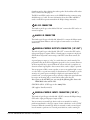
CONNECTING THE CPU CARD
The rear-connector panel associated with the CPU card holds seven connectors,
as illustrated in Figure 6. The following sections describe each connector. The
Installation Chapter of this manual gives pin assignments for each connector.
Note: A matrix only requires one rear-panel CPU card, because whichever of the
two front-installed CPU cards is acting as master will work in conjunction
with this card. All other cards, however, require their own rear-connector
panel.
1 GPI/RLY Interface Connector
(RJ-45)
RS-232 Connector (male 9-pin D-type) 2
General Purpose Outputs Connector 4
(male 25-pin D-type)
3 Alarm I/O Connector
(female 9-pin D-type)
5 General Purpose Inputs Connector
(female 25-pin D-type)
6
LAN 1 Connector (RJ-45)
7 LAN 2 Connector (RJ-45)
Figure 2-6: CPU Card’s Rear-Connector Panel
1 GPI-RLY INTERFACE CONNECTOR
The RJ-45 socket labeled “GPI/RLY Interface” connects the CPU card to a
GPI-6 or RLY-6 card. The GPI-6 provides six general-purpose opto-isolated logic
inputs. The RLY-6 card provides six single-pole, double-throw relay outputs.
Both card types mount in either an IMF-3 interface frame or an IMF-102
interface frame. You can operate up to ten GPI-6 or RLY-6 cards at one time
2-16
ECLIPSE OMEGA MATRIX INSTRUCTION MANUAL
from the matrix by daisy-chaining the cards together. Each card has an IN and an
OUT connector for this purpose.
The RLY-6 and GPI-6 cards connect to the GPI/RLY interface connector using
shielded category-5 cable. For more information about the GPI-6 and RLY-6
cards, consult their respective manuals in the Eclipse Omega manual set.
2 RS-232 CONNECTOR
The female 9-pin D-type socket labeled “RS-232” connects the CPU card to an
external computer.
3 ALARM I/O CONNECTOR
The female 9-pin D-type socket labeled “Alarm I/O” connects the Eclipse matrix
to an external alarm indicator, such as a light or buzzer and/or to an external
alarm source.
4 GENERAL-PURPOSE OUTPUTS CONNECTOR (“GP OUT”)
The male 25-pin D-type socket labeled “GP OUT” connects the CPU card to
eight general purpose outputs (GPOs). General-purpose outputs are single-pole
double-throw relays with contact ratings of 30 VDC (volts direct current) at 1
ampere.
A general purpose output or “relay” is a switch that you control remotely. You
program the relay in the ECS configuration program to close a contact whenever
an intercom panel’s key is pressed. When the contact is closed, it completes an
electronic circuit’s signal path so that a remote device, such as a light, is powered.
You can program a GPO to mute a speaker, to turn on an applause light, to turn
on a door lock, or to perform a variety of other functions. For example, to get the
attention of a panel operator working in a high-noise environment such as a
control booth, you can program a relay to switch on a light at his panel each time
he receives an incoming call, to ensure that he will not miss the call.
Note: If you use the GP-OUT port, you must fit the following filter between the
PROC-RCC socket and the cable:
CINCH FA-25PS/1 25W D-type in-line 1000pF filter
(UK supplier: Farnell 322-2676)
5 GENERAL-PURPOSE INPUTS CONNECTOR (“GP IN”)
The female 25-pin D-type socket labeled “GP IN” connects the Eclipse Omega
CPU card to eight general purpose inputs (GPIs).
You can connect an external logic device–such as an external foot switch, a
panel-mounted switch, or the logic output of some other device–to the “GP IN”
connector. When the external logic device is activated, it sends a control signal
into the matrix to perform one of several preset functions, such as turning an
ECLIPSE OMEGA MATRIX INSTRUCTION MANUAL
2-17
intercom panel’s microphone on or off, muting a microphone’s output, or
turning a panel’s speaker off. You choose the function to perform and the panel
upon which it is performed from the assignment program.
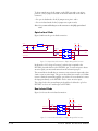
6 LOCAL AREA NETWORK 1 CONNECTOR (“LAN 1”)
The RJ-45 socket labeled “LAN 1” connects a local area network (LAN) to the
CPU card through a standard Ethernet connection. The green LED indicates
the port is connected and the amber LED indicates activity.
If you use this port, you must add a ferrite to the socket end of each cable. A
suitable ferrite is Würth Electronik part: 74271132. “
7 LOCAL AREA NETWORK 2 CONNECTOR (“LAN 2”)
The RJ-45 socket labeled “LAN 2” connects a second local area network (LAN)
to the CPU card through a standard Ethernet connection. The green LED
indicates the port is connected and the amber LED indicates activity.
If you use this port, you must add a ferrite to the socket end of each cable. A
suitable ferrite is Würth Electronik part: 74271132.
CONNECTING PORT CARDS
Each rear-connector panel associated with an MVX-16 port card holds the
sixteen RJ-45 connectors that connect the matrix to intercom panels and
interfaces. Each front-installed MVX-A16 port card requires a corresponding
rear-connector panel. Blank panels cover unused slots.
You can locate and identify each port on the matrix by using the rear-panel
numbering grid.
• Columns 1 through 15 identify cards.
• Rows 1 through 16 identify ports on each card.
• Processor cards are designated P1 and P2.
You can identify a port precisely by identifying its card number and port number
on the card. For exaample, the ports on the first card are designated 1-1, 1-2, 1-3,
1-4, and so on; the ports on the second card are designated 2-1, 2-2, 2-3, 2-4,
and so on.
Each rear-connector panel associated with a fiber card hold two fiber connection
ports. Each front-installed E-FIB card requires a corresponding rear-connector
panel.
Each rear connector panelassociated with an E-Que card hold eleven RJ-45
ports:
• Eight ports for connection to wireless equipment.
• Two ports for DECT sync.
• One port for LAN interface.
2-18
ECLIPSE OMEGA MATRIX INSTRUCTION MANUAL
3
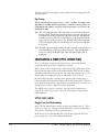
ECLIPSE FIBER CARD LINKING
FIBER CARD DESCRIPTION
E-FIB fiber cards connect Eclipse matrices together to provide a high speed, dual
redundant link to transfer audio samples and data between systems. These
connections can be configured in various ways to provide protection against the
loss of a link or a node.
Each fiber card link consists of a front card with various status indicators and a
rear card with two Duplex LC Terminated fiber optic connectors (TXVRA and
TXVRB). The fiber cards use Simplex fiber optic cables.
Each fiber optic front card has a reset button, status LEDs for power, processor
function, card status, link status and link activity. The link status and activity
LEDs indicate whether there is activity on a link, whether the card is
transmitting on a link and the error state of a link.
Normally fiber cards should be fitted in slots 14 and/or 15 of an Omega matrix.
If fiber cards are fitted to any matrix in a linked system all the linked matrices
must be reset to ensure that all matrices correctly recognise the new hardware.
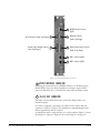
E-FIB FIBER CARD FRONT-PANEL LIGHTS AND CONTROLS
1 Reset Button
Pressing the reset button causes the card and all links to momentarily stop their
current activity and to restart. The card’s “frame data” light goes off when the
reset starts and comes back on when the reset is complete.
During the reset, configuration information downloads to the card and its
connected matrices from the CPU card. If the entire system is operating except
for one fiber card press the reset button for that card only.
NOTE: The reset button is slightly recessed from the front panel to prevent it
from being accidentally pressed. You need a tool, such as a bent paper clip, to
press this button.
2 Power Supply & Status Lights
+3.3-Volt Power Supply LED
The matrix’s +3.3-volt power supply provides electric current to this green light.
When lit, the light indicates that the +3.3-volt supply is present and supplying
electric current to the card.
Processor LED
When lit the LED indicates that the fiber card on-board processor is running
ECLIPSE OMEGA MATRIX INSTRUCTION MANUAL
3-1
Front Card LED
When lit indicates that the front card in functioning normally.
Rear Card LED
When lit indicates that the rear card is functioning normally.
3-2
ECLIPSE OMEGA MATRIX INSTRUCTION MANUAL
1 RESET BUTTON
RESET
+3.3V
PROC
FRONT
REAR
Link active
Indicates link
error
Link active
Indicates link
error
TXVRA
ACT LINK
ERR TXVR
TXVRB
ACT LINK
ERR TXVR
Status
Frame
Data
2 POWER SUPPLY & STATUS LIGHTS
When lit, +3.3 V power supply is on
When lit, the processor is running
When lit the front card is functioning
When lit the rear card is functioning
3 LINK A STATUS LIGHTS
When lit the link is established
Indicates data transmit
4 LINK B STATUS LIGHTS
When lit the link is established
Indicates data transmit
5 STATUS LIGHT
When flashing, this light indicates
card status
FRAME DATA LIGHT
6 When flashing, this light indicates
that information is passing between
the CPU card and this card
Figure 3-1: Front Fiber Card
ECLIPSE OMEGA MATRIX INSTRUCTION MANUAL
3-3
3 Primary Link Status LEDs
These LEDs indicate the status and functioning of the primary (A) fiber optic
link.
Link LED
This LED indicates whether a link has been established on the primary fiber
optic circuit (transceiver A). When illuminated a link is present.
TXVR LED
This LED indicates when data is being transmitted on the primary circuit. It is
illuminated when data is present on the circuit.
ACT LED
This LED is lit if the primary fiber optic circuit is active.
ERR LED
This LED will be illuminated if an error condition is detected on the primary
fiber optic circuit.
4 Secondary Link Status LEDs
These LEDs indicate the status and functioning of the secondary (B) fiber optic
link.
Link LED
This LED indicates whether a link has been established on the secondary fiber
optic circuit (transceiver A). When illuminated a link is present.
TXVR LED
This LED indicates when data is being transmitted on the secondary circuit. It is
illuminated when data is present on the circuit.
ACT LED
This LED is lit if the secondary fiber optic circuit is active.
ERR LED
This LED will be illuminated if an error condition is detected on the secondary
fiber optic circuit.
5 Status LED
The green “frame data” LED illuminates to indicate successful communication
between the fiber master card and the CPU card.
3-4
ECLIPSE OMEGA MATRIX INSTRUCTION MANUAL
6 Frame Data LED
The red “status” light illuminates to indicate a failure in communication between
the fiber card and the CPU card.
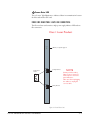
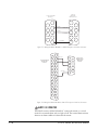
FIBER CARD REAR PANEL LIGHTS AND CONNECTIONS
The fiber card rear card contains a single power supply indicator LED and two
fiber connectors.
Class 1 Laser Product
+3.3V
When lit, +3.3 V power supply is on
TXVRB
NOTE
Secondary Fiber Port
Transceiver
Lasers
Primary and Secondary
Fiber ports are reversed
with respect to the front
panel indicators.
Take care when unplugging
the cables to unplug the
correct cable.
RX
TX
TXVRA
Primary Fiber Port
Figure 3-2: Rear Fiber Card
ECLIPSE OMEGA MATRIX INSTRUCTION MANUAL
3-5
The fiber optic cable for the primary and secondary circuits are plugged into the
appropriate ports.
Eye Safety
This laser based single mode transceiver is a Class 1 product. It complies with
IEC 60825-1/A2:2001 and FDA performance standards for laser products (21
CFR 1040.10 and 1040.11) except for deviations pursuant to Laser Notice 50,
dated July 26, 2001.
Note: The order of the fiber optic cable connections is reversed between the front
and rear panels. On the front panel the primary connection is the upper set
of indicators but on the rear panel it is the lower connector. Similarly the
secondary connetion is the lower set of indicators on the front panel but the
upper connector on the rear panel. Care should be taken when connecting
or disconnecting the cables to ensure that they are connected correctly and
not reversed.
Note: Normally a protective plug is fitted to the fiber connector sockets to protect
them from damage or the entry of foregn materials. These should only be
removed in order to fit the fiber optic cable and replaced if the cable is
unplugged.
CONFIGURING A FIBER OPTIC CONNECTION
There are a number of ways that optical connections can be made between
systems depending on the level of redundancy required.
When a break occurs in the fiber ring, a solid red status light will be shown at the
fiber card downstream from the break and the link status LEDs may show amber.
Other fiber cards will intermittently show red, as the ring attempts to recover. If
the system layout is displayed by ECS the faulty links are shown in red.
In order to diagnose faults or switch between primary and secondary rings or
between primary and backup fiber linking cards the My Systems in ECS must be
used. Ensure that the current configuration is open and click on ‘Live Status’ in
the My Systems toolbar to display the current system state.
This will allow the operator to intevene to alter the system configuration as
required. For details of ECS please refer to the ECS instruction manual (part
number 810299).
SIMPLEX FIBER CABLING
Single Card Set Redundancy
In this case each Matrix Frame contains one fiber-optic Linking card set . This is
shown as in Figure 3-3. This approach still affords fiber connection redundancy
since each rear card houses two fiber-optic transceivers.
In the absence of an Uninterruptible Power Supply this configuration will not
protect against loss of the node or Matrix Frame itself.
3-6
ECLIPSE OMEGA MATRIX INSTRUCTION MANUAL
Figure 3-3: Ring Topology Single Card Set Redundancy
Loss of Single Fiber Connection
If a single fiber connection is lost on one ring and the other ring is intact then the
active ring always attempts to heal itself by reversing the direction of data flow to
bypass the failed connection. If the extent of the failure is such that the active
ring is unable to heal itself then the system will switch to the secondary ring.
The self healing mechanism is performed automatically by the Fiber Linking
Card whereas the switch-over between redundant cards and rings requires
software or operator intervention. Switching to the secondary ring will cause
audio breaks or disturbances and temporary loss of crosspoint data.
If a single fiber connection is lost on both rings the nodes adjacent to the failures
will loop-back their connections to the failed cables healing the rings and the
most intact ring will be used.
The Eclipse Configuration Software (ECS) will report any failures in the fiber
connection system.
ECLIPSE OMEGA MATRIX INSTRUCTION MANUAL
3-7
Loss of a Single Node
If a node is lost on the ring the nodes adjacent to the failed node will loop-back
their connections to the failed node healing the ring using the working remains
of the ring. The configuration software (ECS) will report the failure.
This applies to the situation where the fiber card itself has failed rather than the
matrix.
Loss of Two Fiber Connections
If two adjacent fiber connections are lost on the ring this will be handled as for
the loss of a single node where the nodes adjacent to the failed node will
loop-back their connections to the failed node healing the ring. The
configuration software will report the failure correctly as two failed cables . If two
non-adjacent fiber connections are lost on the ring the nodes adjacent to the
failures will loop-back their connections to the failed cables healing the ring into
2 separate smaller rings. The configuration software will report the failure.
Note that in this instance the two sub-rings will be dependent on their Ethernet
connections for configuration and data transmission but there will be no audio
path between them.
Loss of Two Nodes
If two adjacent nodes are lost on the ring this will be handled as for the loss of
a single node where the nodes adjacent to the failed node will loop-back their
connections to the failed nodes healing the ring. The configuration software will
report the failure correctly as two failed nodes . If two non-adjacent nodes are lost
on the ring the nodes adjacent to the failures will loop-back their connections to
the failed nodes healing the ring into 2 separate smaller rings. The configuration
software will report the failure. Note that in this instance the two sub-rings will
be dependent on their Ethernet connections for configuration and data
transmission but there will be no audio path between them
DUAL CARD SET REDUNDANCY
This is shown as in Figure 3-4 with both " Card set A" and "Card set B" fitted
in each node of the ring. In this case each Matrix Frame contains two Fiber-optic
Linking card sets. This approach affords full redundancy, offering protection
against component failure within a single Fiber-optic Linking Card Set. Again in
the absence of an Uninterruptible Power Supply this configuration will not
protect against loss of the node or Matrix Frame itself.
Loss of Single Fiber Connection
If a single fiber connection is lost on one ring and the other ring is intact then the
active ring always attempts to heal itself by reversing the direction of data flow to
bypass the failed connection. The self healing mechanism is performed
autonomously by the fiber linking card
If the extent of the failure is such that the active ring is unable to heal itself the
the system will switch to the secondary ring. Switching to the secondary ring will
cause audio breaks or disturbances and temporary loss of crosspoint data.
3-8
ECLIPSE OMEGA MATRIX INSTRUCTION MANUAL
The self healing mechanism is performed automatically by the fiber linking card
whereas the switch-over between redundant cards and rings requires software or
operator intervention.
Loss of a Single Node
If a node is lost on one ring due to a single fiber-optic linking card set failure and
the fiber-optic linking card set for the other ring is healthy and the other ring is
intact then the active ring always attempts to heal itself. The nodes adjacent to
the failed node will loop-back their connections to the failed node healing the
ring using the working remains of the ring.
If the extent of the failure is such that the active ring is unable to heal itself the
the system will switch to the secondary ring. Switching to the secondary ring will
cause audio breaks or disturbances and temporary loss of crosspoint data.
The self healing mechanism is performed autonomously by the fiber linking card
whereas the switch-over between redundant cards and rings requires software or
operator intervention.
If a single node is lost on both rings due to multiple fiber-optic linking card set
failures etc the nodes adjacent to the failed node(s) will loop-back their
connections to the failed node(s) healing the rings and the most intact ring will
be used. The configuration software will report the failure.
Loss of Two Fiber Connections
f two adjacent fiber connections are lost on the ring this will be handled as for
the loss of a single node where the nodes adjacent to the failed node will
loop-back their connections to the failed node healing the ring. The
configuration software will report the failure correctly as two failed cables . If two
non-adjacent fiber connections are lost on the ring the nodes adjacent to the
failures will loop-back their connections to the failed cables healing the ring into
2 separate smaller rings. The configuration software will report the failure.
Note that in this instance the two sub-rings will be dependent on their Ethernet
connections for configuration and data transmission but there will be no audio
path between them.
Switching to the secondary ring will cause audio breaks or disturbances and
temporary loss of crosspoint data. The self healing mechanism is performed
autonomously by the fiber Linking Card whereas the switch-over between
redundant cards and rings requires software or operator intervention.
If two adjacent fiber connections are lost on one ring and the other ring has a
similar failure this will be handled as for the loss of a single node where the nodes
adjacent to the failed node will loop-back their connections to the failed node
healing the ring. The configuration software will report the failure correctly as
two failed cables . If two non-adjacent fiber connections are lost on one ring and
the other ring has a similar fault the nodes adjacent to the failures will loop-back
their connections to the failed cables healing the ring into 2 separate smaller
rings. The configuration software will report the failure.
ECLIPSE OMEGA MATRIX INSTRUCTION MANUAL
3-9
Note that in this instance the two sub-rings will be dependent on their Ethernet
connections for configuration and data transmission but there will be no audio
path between them.
Figure 3-4: Ring Topology Dual Card Set Redundancy
Loss of Two Nodes
If two adjacent nodes are lost on the ring this will be handled as for the loss of
a single node where the nodes adjacent to the failed node will loop-back their
connections to the failed nodes healing the ring. The configuration software will
report the failure correctly as two failed nodes . If two non-adjacent nodes are lost
on the ring the nodes adjacent to the failures will loop-back their connections to
the failed nodes healing the ring into 2 separate smaller rings. The configuration
software will report the failure. Note that in this instance the two sub-rings will
be dependent on their Ethernet connections for configuration and data
transmission but there will be no audio path between them
Switching to the secondary ring will cause audio breaks or disturbances and
temporary loss of crosspoint data. The self healing mechanism is performed
autonomously by the fiber linking card whereas the switch-over between
redundant cards and rings requires software or operator intervention.
3-10
ECLIPSE OMEGA MATRIX INSTRUCTION MANUAL
If two adjacent nodes are lost on one ring and the other ring has a similar fault
this will be handled as for the loss of a single node where the nodes adjacent to
the failed node will loop-back their connections to the failed nodes healing the
ring. The configuration software will report the failure correctly as two failed
nodes. If two non-adjacent nodes are lost on one ring and the other ring has a
similar fault the nodes adjacent to the failures will loop-back their connections to
the failed nodes healing the ring into 2 separate smaller rings. The configuration
software will report the failure. Note that in this instance the two sub-rings will
be dependent on their Ethernet connections for configuration and data
transmission but there will be no audio path between them.
Fiber-Optic Linking Card Failure
This will be handled as for loss of a single node above. The configuration
software will report the failure.
FAULT TOLERANCE
Dual Card Set Redundant System - Full Redundancy
In the event of single or multiple cable fault or loss of node conditions occurring
on one ring whilst the other ring remains intact the active ring always attempts to
heal itself.
Switching to the secondary ring will cause audio breaks or disturbances and
temporary loss of crosspoint data. The self healing mechanism is performed
autonomously by the fiber linking card whereas the switch-over between
redundant cards and rings requires software or operator intervention.
In all fault cases involving recoverable cable faults or loss of nodes on one or both
both rings the remaining nodes may experience audio breaks or disturbances
and temporary loss of crosspoint information or data. Audio and data from a
failed node will not be available to the remaining nodes for the duration of the
failure. When a ring with non-adjacent failures sub-divides into two sub-rings,
audio and data from the failed nodes will not be available to the nodes in either
sub-ring , audio and data will continue to be available to nodes within the same
sub-ring but data may still be available to all nodes that are still functioning if
there is an intact, independent Ethernet connection to those nodes.
If a Matrix frame, connected as a node of the fiber-optic link is reset, powered
down or failed this will constitute a lost or failed node on both rings and this
node will experience audio breaks or disturbances and loss of crosspoint
information or data for up to 5 seconds after the fault condition is cleared or
repaired.
Single Card Set Redundant System - Fiber Redundancy
In all fault cases involving cable faults or loss of nodes on the ring the
remaining nodes may experience audio breaks or disturbances and loss of
crosspoint information or data. When a ring with non-adjacent failures
sub-divides into two sub-rings, audio and data from the failed nodes will not be
available to the nodes in either sub-ring , audio and data will continue to be
ECLIPSE OMEGA MATRIX INSTRUCTION MANUAL
3-11
available to nodes within the same sub-ring but data may still be available to all
nodes that are still functioning if there is an intact, independent Ethernet
connection to those nodes.
If a Matrix frame, connected as a node of the fiber-optic link is reset, powered
down or failed this will constitute a lost or failed node on the ring and this node
will experience audio breaks or disturbances and loss of crosspoint information
or data for up to 5 seconds after the fault condition is cleared or repaired.
3-12
ECLIPSE OMEGA MATRIX INSTRUCTION MANUAL
4
ECLIPSE E-QUE CARD
E-QUE CARD DESCRIPTION
The E-QUE card allows the Eclipse matrix connectivity to FreeSpeak/CellCom
antennas and FreeSpeak/CellCom antenna splitters. The connection options
supported are:
• 8 x FreeSpeak/CellCom antenna direct connections
• 2 x FreeSpeak/CellCom splitter connections (up to 5 antennas each)
Up to 40 antennas and 200 beltpacks can be connected to a matrix using E-Que
cards.
Each E-Que card set consists of a front card with a reset button and various status
indicators, and a rear card with eleven RJ45 ports giving eight standard ports,
DECT sync in and out and a LAN port.
Each E-Que front card has status LEDs for power, port activity and LAN status.
The port activity LEDs indicate whether there is a device connected to an E1
port and that a connection has been established between this port and the
connected device.
The E-Que cards must be fitted in the rightmost available slots on the Omega
(furthest from the config cards) and up to four E-Que cards can be fitted on a
matrix.
Note: It is not necessary to have an ethernet cable connected to the E-Que card
LAN port for the card to function correctly.
E-QUE CARD FRONT-PANEL LIGHTS
1 Reset Button
Pressing the reset button causes the card and all links to momentarily stop their
current activity and to restart.
During the reset, configuration information downloads to the card from the
CPU card. If the entire system is operating except for one E-Que card press the
reset button for that card only.
Note: The reset button is slightly recessed from the front panel to prevent it from
being accidentally pressed. You need a tool, such as a bent paper clip, to
press this button.
2 Power Supply & Status Lights
+3.3-Volt Power Supply Light
ECLIPSE OMEGA MATRIX INSTRUCTION MANUAL
4-1
The matrix’s +3.3-volt power supply provides electric current to this green light.
When lit, the light indicates that the +3.3-volt supply is present and supplying
power to the card.
4-2
ECLIPSE OMEGA MATRIX INSTRUCTION MANUAL
1 RESET BUTTON
RESET
+3.3V
STATUS
1
2
3
4
5
6
7
8
2 POWER SUPPLY LIGHTS
When lit, +3.3 V power supply is on
3 STATUS LIGHTS
8 yellow lights, one per port
When on, light indicates:
(1) There is a device connected to the port.
(2) Communications are running properly
between the port and the card.
4
LAN DATA LIGHT
The green "LAN DATA" light illuminates
to indicate data is passing through the
ethernet port
5
LAN LINK LIGHT
The amber "LINK" light illuminates to
indicate a connection on the LAN port.
LAN
DATA
LINK
Figure 4-1: Front E-Que Card
ECLIPSE OMEGA MATRIX INSTRUCTION MANUAL
4-3
3 Status Lights
When lit, a “status” light indicates successful communication between the E-Que
card and a connected device such as an active antenna or splitter.
Each of the E-Que card’s 8 yellow “status” lights corresponds to one of 8 ports to
which devices can be connected.
4 LAN Data Light
The green “LAN DATA” light illuminates to indicate there is data passing
through the ethernet port.
5 LAN Link Light
The amber “LAN LINK” light illuminates to indicate a connection to the LAN
port.
E-QUE CARD REAR CONNECTIONS
The E-Que card rear card contains eleven RJ45 connectors; 8 E1/T1 ports, 2
DECT sync ports and a LAN port.
4-4
ECLIPSE OMEGA MATRIX INSTRUCTION MANUAL
LAN Port
(RJ45)
DECT Ref in
(RJ45)
DECT Ref out
(RJ45)
Port 1 (RJ45)
Port 2 (RJ45)
Port 3 (RJ45)
Port 4 (RJ45)
Port 5 (RJ45)
Port 6 (RJ45)
Port 7 (RJ45)
Port 8 (RJ45)
Figure 4-2: Rear E-Que Card
When multiple E-Que cards are fitted in a rack, one of the cards generates a clock
signal, which all othe cards lock to, to ensure that all antennas remain in sync.
The system is designed such that the leftmost card (seen from the front) is always
the one which generates this signal. This means that if the leftmost card is
removed, or a new card is fitted to the left of existing cards, the antennas will lose
lock for a few seconds as the cards re-configure themselves and a new card starts
generating the sync signal.
ECLIPSE OMEGA MATRIX INSTRUCTION MANUAL
4-5
Where multiple connected matrices are used containing E-Que cards the DECT
reference ports are connected as a daisy chain between the matrices to ensure that
the DECT signals are synchronised through all the E-Que cards present in the
matrices.
The LAN port is used for diagnostic purposes.
E-QUE CARD APPLICATIONS
The E-Que card may be used to connect FreeSpeak/CellCom antennas and
splitters to an Eclipse matrix system.
FREESPEAK/CELLCOM APPLICATION
The E-Que cards can be configured for FreeSpeak/CellCom use in two modes
depending on whether antennas or splitters are to be connected.
If the E-Que card is configured in ‘Antenna’ mode all eight E1/T1 ports can be
used to connect up to eight antennas. If the E-Que card is configured to support
splitters only two ports are active (ports 1 and 5) allowing a maximum of two
splitters to be connected. Each splitter can support up to five antennas.
There connections schemes are illustrated below.
4-6
ECLIPSE OMEGA MATRIX INSTRUCTION MANUAL
Antennas
E1/T1
E1/T1
E1/T1
E1/T1
Matrix
E-Que
Rear
E1/T1
E1/T1
E1/T1
E1/T1
Figure 4-3: E-Que Card Antenna Connection
ECLIPSE OMEGA MATRIX INSTRUCTION MANUAL
4-7
Antennas
Antenna
Splitter
E1/T1
Matrix
E-Que
Rear
Port 1
Port 5
E1/T1
Antenna
Splitter
Figure 4-4: E-Que Card Splitter Connection
Each antenna can handle up to five beltpacks simultaneously and switch service
between antennas under control of the matrix as the beltpack user moves around
the site.
Where multiple matrices are networked together with antennas or splitters
connected to E-Que cards on more than one matrix the E-Que cards should have
the DECT Sync links between matrices to ensure the correct operation of the
FreeSpeak/CellCom system.
Multiple E-Que cards within a single matrix do not need to have external DECT
sync cables connected as the signal uses the backplane.
4-8
ECLIPSE OMEGA MATRIX INSTRUCTION MANUAL
LAN
Matrix 1
E-Que
Card 1
Splitter 1
Out
DECT
Sync
In
Matrix 2
E-Que
Card 2
Splitter 2
Figure 4-5: Multiple Matrices with DECT Sync Interconnect
All connections are made using CAT5 cable and it is recommended that shielded
cable is used.
Note: If an E-Que card is fitted in the Omega with antennae or splitters
connected and active inserting a second E-Que card to the left of the first
card (seen from the front) will cause a temporary loss of audio to beltpacks
using the original E-Que card (usually for about 10 seconds). The
beltpacks do not go offline and signalisation is not lost.
ECLIPSE OMEGA MATRIX INSTRUCTION MANUAL
4-9
4-10
ECLIPSE OMEGA MATRIX INSTRUCTION MANUAL
5
INSTALLATION
RECONNECTING THE CPU CARD’S BACKUP BATTERY
MPORTANT: Before you install the Omega you must reconnect the CPU backup
battery.
The CPU card has a lithium backup battery that powers the CPU memory if the
AC electricity fails. This backup battery is shipped disconnected to preserve
battery life. When you receive the matrix, you must reconnect the battery.
The matrix will operate if you do not reconnect the battery. However, if you
power down the matrix you will lose all configuration information stored in the
matrix’s CPU card.
To reconnect the CPU memory’s backup battery:
The Eclipse Omega matrix
installs in a standard
Electronic Industry
Association 19-inch (48 cm)
equipment rack.
1. Please observe anti-static procedures. The CPU card can be damaged by static
electricity. Please ground yourself and tools before touching cards.
2. Locate CON9 on the centermost upper portion of the CPU card.
Under the CON9 heading, there are three pins. A jumper plug is placed over
pins 2 and 3. This is the OFF position.
3. Lift the jumper plug off the pins, and place it over pins 1 and 2. This is the
ON position.
The battery is now powered.
DETAIL OF CON9
1
2
3
ON
CPU CARD
Figure 5-1: CPU card with detail of CON9 jumper plugs
ECLIPSE OMEGA MATRIX INSTRUCTION MANUAL
5-1
Before performing any service on the CPU card, you must disconnect the card’s
battery. To do so, place the CON9 jumpers in the OFF position as described in
the previous procedure.
PIN
STATUS
1
On
2
Common
3
Off
Table 5-1: CON9 Pin Configuration
If you are going to store the matrix for more than 3 months, or if you regularly
turn off the power to the matrix, you need to temporarily deactivate the CPU
backup battery while the matrix is stored. To do so, put the CON9 jumper in the
OFF position as described above. When you wish to power up and start
operating the matrix, reconnect the CPU backup battery by placing the CON9
jumper in the ON position, as described above.
CAUTION: Danger of explosion if battery is incorrectly replaced. Replace only
with the same or equivalent type.
Lithium batteries can overheat or explode if they are shorted. When you handle the
CPU card or a loose battery, DO NOT touch any external electrical conductors to the
battery’s terminals or to the circuits that the terminals are connected to.
Whenever you are servicing the battery, make sure that the jumper on CON9 is
connecting pin 2 (common) to either pin 1 (on) or to pin 2 (off ). If the common is left
floating, the CPU may behave unpredictably. For example, the microprocessor may
reset itself intermittently.
VERIFYING THE SHIPMENT
When you receive your Eclipse Omega system, inspect the boxes for shipping
damage. Report any shipping damage to the carrier. Your Eclipse Omega
distributor is not responsible for shipping damage.
Check the packing list and verify that you received every item on the list. Save all
packing materials in the event you need to return any items.
UNPACKING THE SYSTEM
When you receive your Eclipse Omega system, the circuit cards, power supplies,
and rear-connector panels are pre-installed in the matrix chassis. You need to
supply:
• A standard 19-inch rack in which to install the matrix.
• A personal computer to run the Eclipse Configuration System (ECS). The
Eclipse Configuration System runs on Windows XP, Windows Server 2003
and Windows 2000.
5-2
ECLIPSE OMEGA INSTRUCTION MANUAL
• Shielded category-5 cables to connect to panels and interfaces.
INSTALLING THE ECLIPSE OMEGA MATRIX
The following overview gives you a summary of the steps required to install an
Eclipse Omega matrix. More detailed information on each step is provided in the
sections that follow.
To install an Eclipse Omega matrix:
1. Remove the Eclipse Omega matrix chassis from its shipping carton.
2. Leave at least 2 inches (51 mm) of clearance on all sides of the matrix chassis to
ensure proper airflow. Do not block ventilation vents.
3. Check the position of circuit cards, power supplies, and rear-connector panels.
Later sections in this chapter give more information on these items.
4. Apply AC power to the unit. The unit has two separate AC power entry
connectors for the two separate power supplies in the system.
INSTALLING POWER SUPPLIES
The Eclipse Omega system’s DC power supplies run on AC mains power. Two
identical Euro Cassette power supplies are provided to ensure that every matrix
will have redundant power—that is, to ensure that the matrix will continue to
operate even if one supply output fails.
Each of the power supplies must be connected to a dedicated branch of AC
mains power. The matrix will continue to operate even if one of the AC power
branches fails.
Clear-Com ships each matrix with power supplies already installed. When you
receive the matrix, connect the power supplies to AC mains power using the IEC
power connectors on the matrix’s rear panel.
A fully equipped Eclipse Omega matrix (13 port cards, 2 expansion cards)
requires 100 to 240 VAC at 40 to 50 Hz with a maximum dissipation of 400 W.
INSTALLING THE REAR RJ-45 CONNECTOR PANELS
The matrix’s rear panel is constructed of modular, individually-installable
connector panels. Each port or expansion card has a corresponding
rear-connector panel. Each MVX connector panel holds 16 RJ-45 connectors.
Clear-Com ships each matrix with the required number of rear-connector panels
already installed. Blank rear panels fill unused card slots.
INSTALLING REAR RJ-45 CONNECTOR PANELS IN
THE FIELD
Installing or removing a rear panel from the matrix is a simple procedure,
allowing you to easily customize the matrix to your operating environment.
To add a rear panel to the matrix:
ECLIPSE OMEGA MATRIX INSTRUCTION MANUAL
5-3
1. Remove the desired blank rear panel by loosening the screws and pulling the
panel out. The screws are attached and cannot be removed.
2. Install the new rear panel by sliding the card into the card’s guides at the top
and bottom of the Eclipse Omega chassis.
3. Tighten all of the screws on the rear panel.
To remove a rear panel from the matrix:
1. Detach any devices connected to the rear panel’s connectors.
2. Loosen the screws that hold the rear panel to the matrix. The screws are
attached and will not fall off.
3. Remove the rear panel by pulling the panel out.
INSTALLING CPU CARDS
The CPU card’s components include CMOS chips which are sensitive to static
electricity. Before touching the CPU card with your hands, touch a grounded
metal object, such as any unpainted surface on the matrix, to dissipate static
electricity. While handling the CPU card, be careful not to bend any of the card’s
connector pins or component leads.
Before operating the CPU card, you must reconnect the card’s battery. The CPU
card is shipped with a disconnected battery to preserve battery life. For
instructions on reconnecting the battery, see “RAM Back-Up Battery” on pages
3-3 and 3-4.
Store spare CPU cards in unused slots in the matrix or in electrically insulated
packaging such as anti-static heavy duty plastic bags.
To insert a CPU card in the matrix:
1. Carefully place the card in the appropriate slot. Make sure the card is aligned
with the top and bottom precision guides.
2. When the card has almost reached the backplane connectors, open the two
ejectors, allowing them to clear the edges of the matrix. Gently insert the card
further until it touches the backplane connector guides.
3. Gently close both ejector tabs at the same time, which will propel the card into
the backplane connectors.
To remove a CPU card from the matrix:
1. Two card ejector tabs, located at the top and bottom of the CPU card, hold
the card in place in the matrix. To remove a card, open the two ejector tabs at
the same time until the card unseats from its backplane connectors.
2. Pull the card out of the matrix.
HOT PATCHING
The CPU cards are “hot patchable” and “self initializing.” When the matrix is
fitted with two CPU cards, a faulty CPU card can be removed and replaced while
the system is powered because the second CPU card will automatically begin
operating when the first card is removed. Sometimes, re-inserting a CPU can
reset the matrix. It is advisable to replace CPUs in maintenance down times.
5-4
ECLIPSE OMEGA INSTRUCTION MANUAL
VERIFYING THE CPU CARD INSTALLATION
You can check the CPU card’s operating status by looking at the lights on the
front of the card. The following lights indicate that the card has been properly
installed in the matrix:
• The two power-supply lights, labeled “+5V” and “+3.3V,” illuminate green
steadily to indicate that the power supplies are present.
• The dot-matrix array of lights displays a number to indicate which of the four
stored configurations in the card’s memory is currently operating.
• The “OK” light flashes to indicate that the CPU card software is running.
• The “master” light illuminates steadily on the currently active CPU card,
indicating that the CPU card is properly installed and operating correctly.
INSTALLING PORT AND EXPANSION CARDS
Before installing a port or expansion card, the card’s associated rear-connector
panel should be installed.
To install a port or expansion card:
1. Carefully place the card in the appropriate slot. Make sure the card is aligned
with the top and bottom precision guides.
2. Push the card toward the backplane connectors.
3. When the card has almost reached the backplane connectors, open the two
ejector tabs, allowing them to clear the edges of the matrix. Gently insert the
card further until it touches the backplane connector guides.
4. Gently close both ejector tabs at the same time, which will propel the card into
the backplane connectors.
To remove a CPU card from the matrix:
1. The two card ejector tabs, located at the top and bottom of the CPU card,
hold the card in place in the matrix. To remove a card, open the two ejector
tabs at the same time until the card unseats from its backplane connectors.
2. Pull the card out of the matrix.
STATIC SENSITIVITY
A circuit card’s components include CMOS chips that are sensitive to static
electricity. Before touching a card with your hands, touch a grounded metal
object, such as any unpainted surface on the matrix, to dissipate static
electricity.When handling a card, be careful not to bend any of the card’s
connector pins or component leads.
Store spare cards in electrically insulated packaging such as anti-static heavy duty
plastic bags or in unused port card slots in the matrix.
HOT PATCHING
Port and expansion circuit cards are “hot patchable” and “self initializing,”
meaning that a faulty card can be removed and replaced while the system is
ECLIPSE OMEGA MATRIX INSTRUCTION MANUAL
5-5
powered, having no effect on any part of the system operation, except to the
card’s assigned sixteen ports.
Communication to a card’s connected devices will be interrupted when that card
is removed from the matrix. When the card is replaced, communication is
restored.
SLOT NUMBERING
Each port and expansion card has circuitry to support 16 ports. A grid printed on
the matrix’s rear panel gives the numbering scheme for the ports.
CONFIGURATION
When a port card is physically installed, its ports must be assigned functions
from the Eclipse Configuration System (ECS). Refer to the Eclipse Configuration
System Instruction Manual for more information.
VERIFYING PORT CARD INSTALLATION
You can check the operating status of the matrix by viewing the front-panel
status lights. The following lights indicate that a port card has been properly
installed in the matrix:
• When lit, the four power-supply lights indicate that the associated power
supplies are operating properly. The four lights are +12V, -12V, +5V, and
+3.3V.
• The column of 16 yellow lights labeled “active” corresponds to the card’s 16
ports. When lit, an “active” light indicates that there is a device connected to
that port and that communication is running properly between the card and
the device.
• The column of 16 green lights labeled “VOX” corresponds to the card’s 16
ports. When lit, a “VOX” light indicates the audio level on that port’s
connected audio device has exceeded a threshold. You set the threshold audio
level for that port’s connected audio device in the ECS configuration software.
• The green “frame data” light illuminates green when information has
successfully passed between the CPU card and the port card.
• The red “status” light illuminates when the port card fails to communicate
with the CPU card.
WIRING AUDIO DEVICES TO THE MATRIX
The instruction manual Installing the Eclipse Matrix System: An Overview gives
complete details about wiring audio devices to the matrix. The Overview manual
also discusses RJ-45 cables and other types of cable required for system
installation.
The Eclipse Omega system features two IEC mains AC power connectors that
provide separate power inputs for redundant power supply combinations. If you
5-6
ECLIPSE OMEGA INSTRUCTION MANUAL
connect each AC input to a different mains AC branch, one power supply will
continue to operate if the other supply’s mains AC branch opens.
WIRING PANELS TO THE MATRIX
Eclipse uses a 4-pair (analog) or single-pair (digital) wiring scheme between the
matrix and panels. All Eclipse panels have built-in RJ-45 connectors.
4-Pair Analog
Four-pair analog wiring is done with shielded CAT5 RJ-45 cable.
• Pair 1 transmits analog audio from the matrix to the panel.
• Pair 2 transmits digital data from the panel back to the matrix.
• Pair 3 transmits audio from the panel to the matrix.
• Pair 4 transmits digital data from the matrix back to the panel.
RJ-45 CONNECTOR
AT MATRIX PORT
RJ-45 CONNECTOR ON
STATION OR INTERFACE
8 765 4 321
Views from
front of
connectors
8 765 4 321
Shielded category-5 cables wired pin-to-pin
Matrix Frame RJ-45 Pin Numbers
RS-422 Input +
(into Matrix)
1
RS-422 Input
(into Matrix)
2
Audio Input +
(into Matrix)
3
Audio Output +
(from Matrix)
4
Audio Output
(from Matrix)
5
Audio Input
(into Matrix)
6
RS-422 Output +
(from Matrix)
7
RS-422 Output
(from Matrix)
8
Station RJ-45 Pin Numbers
Pair 2
Pair 1
Pair 3
Pair 4
Pair
Pair
Pair
Pair
1
2
3
4
1
RS-422 Output +
(from station)
2
RS-422 Output
(from station)
3
Audio Output +
(from station)
4
Audio Input +
(into station)
5
Audio Input
(into station)
6
Audio Output
(from station)
7
RS-422 Input +
(into station)
8
RS-422 Input
(into station)
Audio output from Matrix to station
RS-422 data input from station to Matrix
Audio input from station to Matrix
RS-422 data output from Matrix to station
Figure 5-2: Wiring from the Matrix to an Analog Panel Using RJ-45
ECLIPSE OMEGA MATRIX INSTRUCTION MANUAL
5-7
Single-Pair Digital
Single-pair digital wiring is accomplished with double-shielded 24 AWG
conductor CAT-6E enhanced STP cable. Pair 1 transmits and receives
multiplexed digital and analog between the matrix and the panel.
Note: Ensure that the “select” switch on the rear of the panel is in the correct
position for the intended use.
ATT-T568B (Modular Jumpers Wired One to One)
Station End
Matrix Frame End
Pair 2
No Connection (NC)
1
1
No Connection (NC)
2
2
No Connection (NC)
3
Multiplexed Data/Audio
4
Multiplexed Data/Audio
5
No Connection (NC)
6
No Connection (NC)
7
No Connection (NC)
8
Pair 1
3
4
Pair 3
5
6
Pair 4
7
8
Figure 5-3: Wiring from the Matrix to a Digital Panel Using RJ-45
Note: This wiring diagram refers to the Digi-2 unit only.
WIRING CPU CARD INTERFACES
The central processor unit (CPU) card holds the circuitry for connecting to, and
communicating with, the following interfaces:
• An external personal computer
• Alarm inputs and outputs
• Eight general purpose inputs (GPIs)
• Eight general purpose outputs (GPOs or relays)
• Two separate local area network (LAN) connections for Ethernet-based
communication with a network
• An external GPI/RLY interface
5-8
ECLIPSE OMEGA INSTRUCTION MANUAL
1 GPI/RLY Interface Connector
(RJ-45)
RS-232 Connector (female 9-pin D-type) 2
General Purpose Outputs Connector 4
(male 25-pin D-type)
3 Alarm I/O Connector
(female 9-pin D-type)
5 General Purpose Inputs Connector
(female 25-pin D-type)
6
LAN 1 Connector (RJ-45)
7 LAN 2 Connector (RJ-45)
Figure 5-4: CPU Card Interface Connectors
1
GPI/RLY INTERFACE CONNECTOR
For wiring pinout information for GPI/RLY interfaces, see the Relay Interface
Module (RLY-6) Instruction Manual and the General Purpose Inputs (GPI-6)
Instruction Manual in the set of manuals that came with your Eclipse system.
2
RS-232 DB-9 CONNECTOR
The DB-9 connector labeled “RS-232” connects the Eclipse matrix to an
external computer.
To connect a computer to the matrix, run cable from the matrix’s “RS-232”
connector to the PC’s serial port. The maximum recommended length of the
cable is approximately 10 feet (3 meters).
A computer has either a 9-pin serial port or a 25-pin serial port. Figure 5-5 shows
the wiring for a 9-pin port. Figure 5-6 shows the wiring for a 25-pin port.
ECLIPSE OMEGA MATRIX INSTRUCTION MANUAL
5-9
Matrix Frame
"IBM-PC RS-232"
DB-9M Cable Connector
Computer Serial Port DB-9F
Cable Connector
1
1
6
6
2
Receive (RXD)
2
Transmit (TXD)
7
7
Transmit (TXD)
3
3
Receive (RXD)
8
8
4
4
9
9
Ground (GND)
5
5
Figure 5-5: Wiring the Matrix DB-9M to a DB-9F Computer Serial Port Connector
1
14
2
Computer Serial Port
DB-25F Cable
Connector
Transmit (TXD)
1
6
15
3
Receive (RXD)
Transmit (TXD)
Eclipse Frame
"IBM-PC RS-232"
DB-9M Cable
Connector
2
7
16
4
Receive (RXD)
3
8
17
4
5
9
18
Ground (GND)
6
5
19
7
20
8
21
9
22
10
23
11
24
12
25
13
Figure 5-6: Wiring the Matrix DB-9M to a DB-25F Computer Serial Port Connector
3
ALARM I/O CONNECTOR
The DB-9F connector labeled “Alarm I/O” connects the matrix to a control
circuit for an external alarm, such as a light or bell. The external alarm activates
whenever an alarm condition is detected in the matrix.
5-10
ECLIPSE OMEGA INSTRUCTION MANUAL
NOTE: If your computer
does not have a serial port,
and only offers USB,
adapters are generally
available from computer
parts suppliers.
The following conditions trigger an alarm:
1. If any of the voltages produced by the first power supply unit fall below their
normal levels.
2. If any of the voltages produced by the second power supply unit fall below
their normal levels.
3. If an external alarm circuit or other logic circuit connected to the power supply
is activated.
4. If either of the two power-supply unit fans stop operating.
5. If software on a master CPU card generates an alarm.
An alarm condition activates the relay contacts connected to pins 4, 5, and 9.
These contacts are “dry,” (no voltage is supplied to them by the matrix) and are
rated at 1 A at 24 VDC. They should not be used for AC mains line current.
Pins are provided for adding an additional alarm source to the matrix’s alarm
system. Pin 6 is an alarm input to the Eclipse Omega matrix. It is connected to
the input of a 3.3 V logic device. A logic high on this input will cause the Eclipse
Omega matrix to detect an alarm condition. A logic low or an open circuit will
cause the Eclipse Omega matrix to detect no alarm condition.
Pin 1 is a voltage source out of the Eclipse Omega matrix. It is connected
through a 10Kohm pull-up resistor to the +5 V supply rail inside the Eclipse
Omega matrix.
A contact closure placed across pins 1 and 6 will also cause an alarm condition.
The alarm outputs of the PSU-101 power supply could be wired directly to these
pins allowing the CPU card to report PSU failures also.
1
6
To Alarm
2
To Alarm
PSU-101
"Alarm Relay"
Connector
3
2
Eclipse
"Alarm I/O" DB-9F
Connector
1
7
4
3
8
4
Relay Normally Closed
9
5
Relay Normally Open
Relay Wiper/Common
Figure 5-7: Wiring the Alarm I/O Connector to an Alarm Relay Connector
ECLIPSE OMEGA MATRIX INSTRUCTION MANUAL
5-11
ALARM_COM
2
ALARM_NC
3
4
9
ALARM_NO
8
7
1
10
RL1
RELAY DPDT
Figure 5-8: Eclipse Omega Matrix’s Double-Pole Double-Throw Alarm Relay
4
GENERAL-PURPOSE OUTPUTS CONNECTOR (GP OUT)
The DB-25 connector labeled “GP OUT” connects the matrix to eight
double-pole double-throw (DPDT) relays with contact ratings of 30 VDC at 1A.
Each general-purpose output has a relay inside the Eclipse Omega matrix. When
a general-purpose output is inactive, the associated “common” pin on the GP
OUT connector will be shorted to the relevant “normally closed” pin. When a
general-purpose output becomes active, the short between the “common” pin is
broken and a new connection is made between the “common” pin and the
“normally open” pin.
5-12
ECLIPSE OMEGA INSTRUCTION MANUAL
DB-25 Male Connector
PIN
1
2
3
4
5
6
7
8
9
10
11
12
13
14
15
16
17
18
19
20
21
22
23
24
25
DESCRIPTION
RELAY
RELAY
RELAY
RELAY
1
1
1
2
Common
Common
Normally Closed
Normally Open
Common
RELAY 2 Normally Closed
RELAY 2 Normally Open
RELAY 3 Common
RELAY 3 Normally Closed
RELAY 3 Normally Open
RELAY 4 Common
RELAY 4 Normally Closed
RELAY 4 Normally Open
GROUND
RELAY 5 Common
RELAY 5 Normally Closed
RELAY 5 Normally Open
RELAY 6 Common
RELAY 6 Normally Closed
RELAY 6 Normally Open
RELAY 7 Common
RELAY 7 Normally Open
RELAY 7 Normally Closed
RELAY 8 Common
RELAY 8 Normally Closed
RELAY 8 Normally Open
RELAY 1
Normally Closed
Normally Open
Common
RELAY 2
Normally Closed
Normally Open
1
14
2
15
3
16
4
17
5
18
6
19
Common
RELAY 3
Normally Closed
Normally Open
Common
RELAY 4
Normally Closed
Normally Open
7
20
8
21
9
22
10
23
11
24
12
25
Digital Ground
Common
Normally Closed
RELAY 5
Normally Open
Common
Normally Closed
RELAY 6
Normally Open
Common
Normally Closed
RELAY 7
Normally Open
Common
Normally Closed
RELAY 8
Normally Open
13
30 VDC at 1 Ampere
Figure 5-9: Pin Configuration of the General-Purpose Outputs Connector
5
GENERAL-PURPOSE INPUTS CONNECTOR (GP IN)
The DB-25 connector labeled “GP IN” connects the matrix to eight local
general-purpose inputs (GPIs).
The general-purpose inputs operate in one of two modes: the “opto-isolated”
mode or the unisolated mode. The opto-isolated mode requires the externally
connected equipment to provide the current to power the general-purpose input.
The non-isolated mode does not require that the externally connected equipment
powers the general-purpose input. The current is supplied by a voltage output on
the GP IN connector.
ECLIPSE OMEGA MATRIX INSTRUCTION MANUAL
5-13
To select a mode, move the J1 jumper on the CPU rear card to one of two
positions. (The J1 jumper is located on the inner-matrix side of the DB-25
connector.)
• For opto-isolated mode, fit the J1 jumper across pins 1 and 2.
• For non-isolated mode, fit the J1 jumper across pins 2 and 3.
Note: It is recommended that you set the connector to the fully opto-isolated
mode.
Opto-Isolated Mode
Figure 5-10 shows the opto-isolated connection.
U
EXTVIN+
7-24V
8
+
C
10uF_25V
D
BYG22D
VIN
VOUT
LM78L05ACM
1
+3V3
+
+3V3
R
33K2
C
10uF_10V
R
33K2
U
R29 1.5K
EXTVIN-
1
8
EXTERNAL INPUT 1
2
7
3
6
R30
INPUT 1
INPUT 2
1.5K
EXTERNAL INPUT 2
4
5
MOCD207-M
Figure 5-10: Opto-Isolated Connection to Eclipse Omega GPI Connector
In this mode, a DC voltage of between 7 and 24 volts is required at the
EXTVIN+ pin with relation to the EXTVIN– pin. To cause an input to detect
an active signal, you must send current from the relevant input pin.
The external device should draw no current to cause an inactive input and at least
5 mA to cause an active input. The opto-isolator drive line contains a 1.5 kOhm
resistor to limit the current through the opto-isolator. You can therefore connect
the input pins directly to the EXTVIN– level to cause an active input.
The voltage level at the external input pin should not be allowed to go below
EXTVIN– or above +6 V with respect to EXTVIN–.
Non-Isolated Mode
Figure 5-11 shows the non-isolated connection.
+3V3
+3V3
+3V3
R
33K2
R
33K2
U
R29 1.5K
EXTERNAL INPUT 1
R30
EXTERNAL INPUT 2
1
8
2
7
3
6
4
5
INPUT 1
INPUT 2
1.5K
MOCD207-M
Figure 5-11: Non-Isolated Connection to Eclipse Omega GPI Connector
5-14
ECLIPSE OMEGA INSTRUCTION MANUAL
To cause an input to detect an active signal, you must send current from the
relevant input pin.
The external device should draw no current to cause an inactive input and at least
5 mA to cause an active input. The opto-isolator drive line contains a 1.5 kOhm
resistor to limit the current through the opto-isolator. You can therefore connect
the input pins directly to a ground pin to cause an active input.
The voltage level at the external input pin should not be allowed to go below
ground or above +6 V with respect to ground.
Pin Assignments for General-Purpose Inputs Connector
Figure 5-12: Pin Assignments for Eclipse Omega General-Purpose Inputs Connector
ECLIPSE OMEGA MATRIX INSTRUCTION MANUAL
5-15
LOCAL AREA NETWORK CONNECTORS (LAN1 AND LAN2)
The “LAN1” and “LAN2” connectors have standard Ethernet pin assignments.
LAN1 and LAN2
Ethernet RJ-45 Connectors
8 765 4 321
PIN
1
2
3
4
5
6
7
8
FUNCTION
Transmit data +
Transmit data –
Receive data +
Unused
Unused
Receive data –
Unused
Unused
Figure 5-13: Pin Assignments for LAN1 and LAN2 Connectors
5-16
ECLIPSE OMEGA INSTRUCTION MANUAL
6
MAINTENANCE
INTRODUCTION
The Eclipse Omega matrix system connects a complex network of
microprocessor controlled devices. Due to the complexity of the system, you
should limit field service to isolating a problem to the specific circuit board that
may be causing the problem. Once the circuit board has been identified, it can be
either repaired or replaced.
ROUTINE MAINTENANCE RECOMMENDATIONS
MAINTAINING THE MATRIX
Due to the complexity of the
system, field service
generally should be limited
to isolating the specific
component with the
problem.
Because the matrix has moving air in it, the entire matrix should be cleaned at
least once a year. To clean the matrix, shut off AC power, remove all cards, and
use compressed air to remove any dust buildup in the matrix itself. Clean all
cards with a brush to remove dust buildup.
WARNING: Care should be taken not to induce a static discharge in the cards.
Use of a grounding wrist strap is recommended. If a grounding wrist strap is not
available, touch an unpainted metal surface on the matrix chassis periodically to
neutralize static electricity.
RECOMMENDED SPARE PARTS
To facilitate quick repair of the system with minimum downtime, Clear-Com
recommends keeping the following spare system components in good working
condition at all times:
• One CPU card
• One port card
• One Euro Cassette power supply module
• One of each type of intercom panel in the system
• One of each type of interface in the system
FAIL-SAFE MODES
High reliability is one of the main objectives of the Eclipse Omega system design.
The following features of the system minimize the effects of a component failure.
ECLIPSE OMEGA MATRIX INSTRUCTION MANUAL
6-1
DUAL, INDEPENDENT POWER SUPPLIES
The Eclipse Omega matrix includes two Euro Cassette power supply units. One
power supply unit can power an entire matrix; the second unit provides a backup
in case of an equipment failure.
In addition, the two supplies have separate IEC connectors to AC mains power,
and are designed for completely automatic and transparent changeover between
supplies in the event of a power failure on one of the AC branches.
CAUTION: To reduce the risk of electric shock, plug each of the power cords to
separate branch circuits with different service ground.
POWER SUPPLY ALARM OUTPUT
The power supplies contain an over-temperature sensor that is connected to both
an audible alarm and a warning light, giving you the necessary forewarning to
diagnose and correct any power anomalies while the system remains operational.
If any individual power supply fails, an alarm can be issued to a remote location
to alert operators that part of a power supply has failed. The failure of a single
supply will issue an alarm, but the Eclipse Omega system will continue to operate
normally, powered by the second supply.
“HOT PATCHABILITY”
All CPU cards, port cards, and all Euro Cassette power supplies are “hot
patchable”– that is, they can be plugged in or removed from the matrix while the
power is on, and they will be neither damaged, nor will they cause damage to the
system. In addition, the system smoothly incorporates a newly added card.
Sometimes re-inserting a CPU card can reset the matrix. Replace CPU cards
during maintenance down times if possible.
ONBOARD PROCESSORS
If one port card malfunctions, the malfunction will normally affect only the
panels connected to that port card. The malfunction should not affect any other
cards or panels in the system. In all cases, removing a faulty card affects only the
devices connected to that card.
FAIL-SAFE COMMUNICATION
In the event of a CPU card failure, the second CPU card takes over operation of
the system, while the first card is repaired or replaced.
TROUBLESHOOTING
When attempting to identify the cause of the trouble, it is helpful to begin with
the two most basic areas which cause malfunctions:
• The flow of electric current from the power supplies to the cards.
6-2
ECLIPSE OMEGA MATRIX INSTRUCTION MANUAL
• The flow of data between the program software, the circuit cards, and the
attached audio devices.
The following sections discuss troubleshooting these two basic categories of
problems.
TROUBLESHOOTING POWER-SUPPLY PROBLEMS
General Principles
Electric current in the matrix starts at the power supplies, travels through the
matrix’s backplane connectors, and then travels to the circuit cards themselves.
When power-supply problems occur, those three areas—the power supplies, the
backplane connectors, and the circuit cards—should be explored to identify
where the trouble is occurring. Solving power-supply problems starts with
identifying the specific component causing the problem.
Note: The matrix’s backplane connectors are part of the matrix’s infrastructure
and are not serviceable by field personnel. If you determine that a problem
is in the matrix’s backplane connectors, you must send the matrix in for
repair. Backplane connector malfunctions are rare, but should be
considered as possiblities.Clear-Com will ship a spare matrix to use while
the damaged matrix is being repaired.
If you need to send any equipment back to Clear-Com, follow the procedure
described in the Warranty chapter of this manual for obtaining a return
authorization number from the Clear-Com Service Department.
A lit power-supply light on a component indicates that the matrix’s electric
current has traveled successfully to that component and is powering the
component. For example, if the power-supply lights on the CPU card are lit, the
electric current has successfully traveled from the matrix’s power supplies to the
CPU card.
If a power-supply light is not lit on a component, the electric current has not
reached that component for some reason. Knowing where the current has stalled
helps to identify the component that needs repair.
For example, if all of the power-supply lights on all cards do not light, the
electricity supply may have given out either in the power supplies themselves or
in the matrix’s backplane connectors. A faulty connector on the backplane, or a
crack in the backplane can cause all of the matrix’s power-supply lights to go out
because the path on which the electric current is traveling has been blocked.
This is a rare problem, but one to consider as a possibility. Repairing the problem
in this case would involve determining whether the problem is in the power
supplies or the backplane connectors.
When you identify a problem in the power supplies, the backplane connectors,
or the circuit cards, you can then swap out the suspect component with a
properly functioning component to see if the problem is repaired.
ECLIPSE OMEGA MATRIX INSTRUCTION MANUAL
6-3
Specific Troubleshooting Examples
Troubleshooting more specific problems becomes easier when keeping these
general principles in mind. The following examples describe specific problems
and suggested solutions.
Problem: All of the power supply lights do not illuminate on one
port card.
Before repairing or replacing card, try to determine where the problem is
occurring. You can try one or both of the following options:
OPTION 1 Take the bad card out of the matrix, and insert it into a known good
slot in the matrix.
• If the power supply lights still do not illuminate, the problem is probably in
the card itself. Repair or replace the card.
• If the power supply lights illuminate, the problem may be in the matrix’s
backplane connectors, which carry electric current from the power supplies
to the cards. You can send the matrix to Clear-Com for investigation or
repair. In the meantime, you can substitute another matrix for the damaged
one. Clear-Com will send you a matrix to use while the damaged one is
being repaired.
OPTION 2 Take a known good card, and insert it into the bad slot.
• If the power supply lights illuminate, the problem is probably in the card.
Repair or replace the card.
• If the power-supply lights do not illuminate, the problem may be in the
matrix’s backplane connectors, which carry electric current from the power
supplies to the cards. You can send the matrix to Clear-Com for
investigation or repair. In the meantime, you can substitute another matrix
for the damaged one. Clear-Com will send you a matrix to use while the
damaged one is being repaired.
Once you have isolated the problem to the card or the backplane, it is easier to
take the next step which is to repair or replace the suspect component.
Problem: The power supply lights do not illuminate on all cards in
the matrix.
In this situation, the most probable problem is that the matrix’s power supplies
are not sending out any electric current, since none of the cards are receiving
power. Although less likely, the problem may be in the matrix’s backplane
connectors.
The following procedure helps you isolate where the trouble is occurring:
Check the power supplies’ alarm lights. If the power alarm lights are indicating
a problem with the power supply, swap it out with a new power supply.
• If this repairs the problem, the problem was in the power supply.
• If the problem persists even after the power supply has been replaced, the
problem is in the matrix’s backplane connectors. Send the matrix back to
Clear-Com for repair or replacement. In the meantime another matrix can
6-4
ECLIPSE OMEGA MATRIX INSTRUCTION MANUAL
be substituted for the damaged one. Clear-Com will send you a matrix to
use while the damaged one is being repaired.
Problem: The power supply lights do not illuminate on one of the
two CPU cards.
When the system is functioning properly, the power-supply lights on both CPU
cards illuminate. If the power-supply lights on a CPU card fail to illuminate, the
problem may be with the card itself, or with the backplane connectors that carry
the electric current from the power supplies to the cards. (The backplane
connectors are part of the infrastructure of the matrix and are not serviceable by
field personnel.)
The following procedure helps you to isolate where the trouble is occurring:
1. Swap the CPU cards. Put the first card in the second CPU slot and the second
card in the first CPU slot. The problem will follow the card or the slot.
• If the power supply lights do not illuminate on the bad card (the card with
the lights out) when it is inserted in the other CPU slot, the problem is
probably in the card.
• If the power-supply lights on the bad card illuminate when the card is
inserted in the other CPU slot, the problem is probably not in the card
itself. The problem may be with the backplane connectors or power
supplies.
2. Check the power supplies’ alarm lights. If the alarm lights are indicating a
problem with the power supply, swap it out with a new power supply.
• If this repairs the problem, the problem was in the power supply.
• If the problem persists even after the power supply has been replaced, the
problem is in the backplane. Send the matrix back to Clear-Com for repair
or replacement. In the meantime, you can substitute another matrix for the
damaged one. Clear-Com will send you a substitute matrix to use while the
damaged one is being repaired.
Problem: The power supply lights are out on both CPU cards.
The problem may be with power supplies, since both cards appear not to be
receiving power. Although less likely, the problem may be in the matrix’s
backplane connectors.
The following procedure helps you isolate where the trouble is occurring:
Check the power supplies’ alarm lights. If the alarm lights are indicating a
problem with the power supply, swap it out with a new power supply.
• If this repairs the problem, the problem was in the power supply.
• If the problem persists even after the power supply has been replaced, the
problem is in the backplane. Send the matrix back to Clear-Com for repair
or replacement. In the meantime another matrix can be substituted for the
damaged one. Clear-Com will send you a substitute matrix to use while the
damaged one is being repaired.
ECLIPSE OMEGA MATRIX INSTRUCTION MANUAL
6-5
TROUBLESHOOTING DATA PROBLEMS
General Principles
The other type of problem that can occur in the system is when data is not
flowing properly between the program software, the circuit cards, and the
attached panels and interfaces. A troubleshooting sequence in this situation
would be to first check cabling, then reset the card or panel, then reset the entire
system.
Port Card Reset Button
Resetting the port card causes the configuration information for the card and its
attached devices to reload to the card from the CPU card’s operational memory
(located in its microprocessor’s RAM), thus clearing up any corruption of data
that may have occurred in the port card’s microprocessor. The card and all
connected panels and interfaces momentarily stop their current activity and
restart. The reset button must be pressed for more than two seconds to take
effect.
If the entire system is operating except for one port card, or one or more panels
connected to the card, press the reset button for that card only.
Note: This button is slightly recessed from the front panel to prevent it from being
accidentally pressed. You need a tool, such as a bent paper clip, to press this
button.
CPU Card Reset Button
When you reset the CPU card by pressing its reset button, the card’s non-volatile
RAM reloads all configuration information to the card’s microprocessor.
Resetting the card clears any corruption of data in the card’s microprocessor. The
card momentarily stops its current activity and restarts.The same system
configuration that was active before you reset the card will be active after you
reset it.
Note: The reset button is slightly recessed from the front panel to prevent it from
being accidentally pressed. You need a tool, such as a bent paper clip, to
press this button.
CPU Card Full Reset Button
When you press and hold the full-reset button and simultaneously press the reset
button, the system performs a cold restart. All cards in the matrix reset regardless
of any system preferences in the program software. All audio devices connected
to the cards, such as panels and interfaces, reset as well.
When the cards and connected audio devices reset, they momentarily stop their
current activity and restart. During this process configuration information is
downloaded to the port cards and connected audio devices from the CPU card’s
microprocessor.
The same system configuration that was active before you reset the card will be
active after you reset it. You must press the button for more than two seconds for
the reset to take effect.
6-6
ECLIPSE OMEGA MATRIX INSTRUCTION MANUAL
Note: Under normal operating conditions it is not necessary to perform a full
reset. Technical personnel might perform a full restart if they believe that
the CPU card is operating incorrectly as a result of corruption of the
microproccessor’s internal data or instruction sequence.
Specific Troubleshooting Examples
The following examples describe specific problems and suggested solutions.
Problem: A port light on a port card does not illuminate, although
there is a panel attached to that port.
1. Check the panel and the wiring leading to it.
2. Check the Frame Data light. If there is no indication of matrix
communication to this card while the other cards in the matrix are
communicating, reset the card.
3. Replace the card.
4. Replace the panel.
Problem: Audio sounds low or distorted from a panel.
1. Check the matrix’s currently active CPU card’s power lights. If any of the lights
are not lit, replace the card.
2. Check the port card’s input and output gain settings in the program software.
3. Check the panel’s listen-level adjustment settings in the program software.
SYSTEM BLOCK DIAGRAM
LAN1, LAN2,
GPI, GPO, GPI/RLY,
RS232 SERIAL &
ALARM INTERFACES
INTERFACE TO
GPI/RLY &
2/4 WIRE
INTERFACES
ANALOG
STATION
INTERFACES
MVX16A
REAR
CARD
INTERFACE MODULE BACKPLANE
MVX16A
REAR
CARD
E-Que
rear card
(optional)
Fibre-Net
rear card
(optional)
TERMINATOR CARD
TERMINATOR CARD
INTERFACE REAR CARD
INTERFACE REAR CARD
CONFIG
REAR
CARD
INTERFACE CARD
INTERFACE CARD
POWER
SUPPLY
CONN
POWER
SUPPLY
CONN
PSU
PSU
MAIN BACKPLANE
CONFIG
CARD
CONFIG
CARD
MVX16A
CARD
MVX16A
CARD
E-Que
front card
(optional)
Fibre-Net
front card
(optional)
ALARM
CARD
Figure 6-1: System Block Diagram
ECLIPSE OMEGA MATRIX INSTRUCTION MANUAL
6-7
6-8
ECLIPSE OMEGA MATRIX INSTRUCTION MANUAL
7
SPECIFICATIONS
OMEGA MATRIX TECHNICAL SPECIFICATIONS
0 dBu is referenced to 0.775 volts RMS
Matrix Capabilities
Ports per Port Card
Maximum Port Cards
Maximum CPU Cards
Maximum Fibre Expansion Cards
Maximum E-Que Expansion Cards
Maximum Power Supply Units
Maximum RJ-45 Ports per Matrix
Mechanical
Height
Width
Depth
Front Card Depth
Weight
Power Consumption
Temperature
Humidity, Maximum
Matrix Performance
Sample Rate
Resolution
Frequency Response @ 48 kHz sampling
Crosstalk (adjacent channel)
Nominal Level
Matrix headroom
Distortion
Off Noise
On Noise
Key Response, Intra-System
Linked Systems
Fiber Interface Front Card
Height
Depth
Temperature
Humidity
Power
ECLIPSE OMEGA MATRIX INSTRUCTION MANUAL
16
15
2 (included)
2
4
2 (included)
240
10.6 inches (267 mm or 6 RU)
19 inches (482 mm)
16 inches (410 mm)
300 mm
20 to 35 kg
300 W Maximum
0 to +50 ° C, ambient; -55 ° to +70 ° C, storage
90% non-condensing
48 kHz
24 bit
30 Hz – 22 kHz ± 3 dBu
<–70 dBu
0 dBu
+18 dBu
<0.05 %, @ 0 dBu, 300 Hz to 10 kHz;
<0.1 %, @ 0 dBu, 100 Hz to 20 kHz
<–100 dBu relative to +20 dBu,
20 Hz - 22kHz
<–85 dB relative to +20 dBu, 20 Hz - 22 kHz
<40 ms for audio route
<60 ms for audio between matrices
6RU
300 mm
0 to +40 ° C, operating; -55 ° to +70 ° C storage
40 - 90% non-condensing
+3.3V
7-1
Fiber Interface Rear Card
Height
Depth
Temperature
Humidity
Power
6RU
58mm (max)
0 to +40 ° C, operating; -55 ° to +70 ° C storage
40 - 90% non-condensing
+3.3V
E-Que Interface Front Card
Height
Depth
Temperature
Humidity
Power (combined cards)
E-Que Interface Rear Card
Height
Depth
Temperature
Humidity
Analog Port Card
Height
Depth
Audio Interface
Input Format
Output Format
Ground Isolation
Port Card Outputs
Level
Impedance
Frequency Response
Distortion
0 dBu nominal
100 Ohms balanced
30 Hz–22 kHz ± 3 dB
<0.05 %, @ 0 dBu, 300 Hz to 10 kHz;
<0.1 %, @ 0 dBu, 100 Hz to 20 kHz
0 dBv nominal
600 Ohms balanced
30 Hz–22 kHz ± 3 dB
<0.05 %, @ 0 dBu, 300 Hz to 10 kHz;
<0.1 %, @ 0 dBu, 100 Hz to 20 kHz
Data Interface: 16 bi-directional
7-2
6RU
58mm (max)
0 to +40 ° C, operating; -55 ° to +70 ° C storage
40 - 90% non-condensing
6 RU
300 mm
16, bi-directional
Balanced
Balanced
None; expected at User Panel/Station
Port Card Inputs
Level
Impedance
Frequency Response
Distortion
Input Format
Output Format
Input Termination
Output Termination
Isolation
6RU
300 mm
0 to +40 ° C, operating; -55 ° to +70 ° C storage
40 - 90% non-condensing
+3.3V 3.5A
+5V 0.7A
+12V 0.05A
RS-422 @ 2400 to 19200 kb/s
RS-422 @ 2400 to 19200 kb/s
100 ohm ± 10%
None; expected at User Station
None; expected at User Station
ECLIPSE OMEGA MATRIX INSTRUCTION MANUAL
Backplane Connector: FCI/BERG Metral
Port Connector
Transmission Distance
System Programming
Group Calls
Number of Grouped Ports
Conferences per Matrix
IFB per Matrix
Priority Levels
Isolates
Listen Level Control
Input Level Control
Output Level Control
VOX Input Detection Threshold
RJ-45 to Clear-Com standard pinout
3000 ft. (1000 m) maximum
100
4000 maximum
64
100
5
Any crosspoint
0.71 dB steps
0.355 dB steps
0.355 dB steps
0 dB to – 32 dB adjustable
Minimum PC Requirements
Processor
Pentium III 600 MHz (minimum
recommended)
Memory
512 MB RAM minimum
Hard Disk
500 MB free space
Input Devices
3.5-inch Floppy Disk Drive, CD-ROM Drive
Display Resolution
SVGA
User Entry
Keyboard, Mouse
Ports
2 serial ports
Network
IEEE 802.3 Ethernet Card
Operating Systems
Windows XP Professional SP2 / Server 2003
SP1 / 2000 SP4
Note: For details of software requirements please refer to the ECS User Manual part no.
810299.
Power Supply Unit
Format
Quantity
Mounting
Backplane Connectors
AC Power Input
Input Voltage
Power Consumption
Status Indicators
Euro Cassette
2 per matrix
Front
Positronics
IEC (1 per PSU)
AC 100 V to 240 V, 50/60 Hz
400 W maximum
LEDs viewable from front of rack
Notice About Specifications
While Clear-Com makes every attempt to maintain the accuracy of the
information contained in its product manuals, that information is subject to
change without notice. Performance specifications included in this manual are
design-center specifications and are included for customer guidance and to
facilitate system installation. Actual operating performance may vary.
ECLIPSE OMEGA MATRIX INSTRUCTION MANUAL
7-3
7-4
ECLIPSE OMEGA MATRIX INSTRUCTION MANUAL
8
GLOSSARY
Bus A bus is the channel or path between the components in the matrix along
which electrical signals flow to carry information from one component to the
next. In the Eclipse matrix the bus is located in the etched surface of the
midplane.
Call Signal A call signal is an electronic signal sent from one station or
interface to another. A call signal can be audible and/or visual. Typically a call
signal is sent to get the attention of a station operator who may have turned
down their intercom speaker’s volume or removed their headset. It can also be
sent to activate an electronic relay.
Category-5 cable EIA/TIA 568 category specification relating to network
cabling. Shielded category-5 cabling is required for Eclipse matrix wiring.
Central Matrix The term “central matrix” is used to differentiate the central
hardware and software of the intercom system from the connected audio devices.
The central matrix consists of: (1) the metal housing for the circuit cards and
power supplies, (2) the circuit cards, (3) the power supplies, (3) the rear panel
connectors which connect the matrix’s hardware to stations and interfaces.
Destination A device—such as an intercom station, beltpack, or interface—to
which you send audio signals. The device from which you send audio signals is
called a “source.”
Duplex All real-time communication between individuals talking face to face is
full duplex, meaning that you can both talk and listen simultaneously. The
Eclipse Omega matrix provides full-duplex audio.
Eclipse Configuration System Software program that guides the operation
of the central matrix circuit cards and connected stations.
Ethernet International standard which describes how information is
transmitted across a network. Provides for the efficient organization of network
components.
IFB “Interruptible Foldback.” The term “foldback” refers to sending “program”
audio, or some other audio mix, back to the announcer while he is on the air.
Doing so allows the announcer to monitor himself, other announcers, videotapes
of commercials, or some mix of sources, while he is on the air. This is typically
found in television news and live broadcast events.
The announcer typically wears a small ear piece so he can hear the selected
foldback audio mix. When a director wants to give directions to the announcer
on air, or to announce changes in the program, he must “interrupt” the foldback.
To do this, he uses a channel specifically set up to interrupt the foldback audio.
Interface A piece of electronic hardware designed to convert the 4-wire signals
of a central matrix port to some other form of communication, such as 2-wire
ECLIPSE OMEGA MATRIX INSTRUCTION MANUAL
8-1
party line, telephone, etc. The interface is connected to a central matrix port.
The external non-4-wire device is then connected to the interface.
ISO The ISO function, short for “station ISOlation,” allows you to call a
destination and interrupt all of that destination’s other audio paths and establish
a private conversation. When you complete your call, the destination’s audio
pathways are restored to their original state before the interruption.
Label A label is an alphanumeric name of up to five characters that identifies a
source, destination, or control function accessed by your intercom station. Labels
appear in the displays of the intercom station. Labels can identify stations, ports
interfaced to other external equipment, fixed groups, party lines, and special
control functions.
Non-volatile memory Data stored in the CPU’s firmware (ROM) that is not
lost when the power is turned off.
Panel Also referred to as “station.” Any intelligent intercom device connected to
the rear-panel ports of the central matrix. This term does not refer to devices
connected through interfaces.
Port Any of the Eclipse matrix’s 208 input/output RJ-45 connectors that are
used to connect cable from the matrix to stations and interfaces. Each “port”
connects to a separate audio channel in the matrix intercom system.
Program Any separate audio source that is fed into the intercom channels. In
television applications, for example, “program” audio is the audio that is
broadcast on air.
Station Also referred to as “panel.” Any intelligent intercom device connected
to the rear-panel ports of the central matrix. This term does not refer to devices
connected through interfaces.
Rack Unit or RU Standardized unit of mounting space on a rack panel. Each
rack unit is 1.75 inches (44.45 mm) of vertical mounting space. Therefore 1 RU
is 1.75 inches (44.45 mm) of vertical mounting space, 2 RU is 3.5 inches (88.9
mm), 3 RU is 5.25 inches (133.35 mm), and so on.
Sidetone The sound of your own voice heard in your own earphone as you
speak.
Source In this manual, the term “source” refers to a device—such as an
intercom station, interface, or beltpack —that sends audio into the matrix. The
device to which audio is sent is called a “destination.”
VOX In the Eclipse Omega system, when audio at a station exceeds a threshold,
a light switches on at the station’s port card to visually cue you. The threshold
level is set in the Eclipse Configuration Software.
8-2
ECLIPSE OMEGA MATRIX INSTRUCTION MANUAL
LIMITED WARRANTY
Vitec Group Communications (VGC) warrants that at the time of purchase, the
equipment supplied complies with any specification in the order confirmation
when used under normal conditions, and is free from defects in workmanship
and materials during the warranty period.
During the warranty period VGC, or any service company authorized by VGC,
will in a commercially reasonable time remedy defects in materials, design, and
workmanship free of charge by repairing, or should VGC in its discretion deem it
necessary, replacing the product in accordance with this limited warranty. In no
event will VGC be responsible for incidental, consequential, or special loss or
damage, however caused.
WARRANTY PERIOD
Return Material
Authorization (RMA)
numbers are required for all
returns.
Both warranty and
non-warranty repairs are
available.
The product may consist of several parts, each covered by a different warranty
period. The warranty periods are:
• Cables, accessories, components, and consumable items have a limited
warranty of 90 days.
• Headsets, handsets, microphones, and spare parts have a limited warranty of
one year.
• UHF wireless IFB products have a limited warranty of one year.
• UHF wireless intercom systems have a limited warranty of three years.
• All other Clear-Com and Drake brand systems and products, including
beltpacks, have a limited warranty of two years.
The warranty starts at the time of the product’s original purchase. The warranty
start date for contracts which include installation and commissioning will
commence from the earlier of date of the Site Acceptance Test or three months
from purchase.
TECHNICAL SUPPORT
To ensure complete and timely support to its customers, VGC’s User Support
Center is staffed by qualified technical personnel. Telephone and email technical
support is offered worldwide by the User Support Center.
The User Support Center is available to VGC’s customers during the full course
of their warranty period.
Instructions for reaching VGC’s User Support Centers are given below.
Telephone for Europe, Middle East and Africa: +49 40 6688 4040 or +44 1223
815000
WARRANTY
i
Telephone for the Americas and Asia: +1 510 337 6600
Email: [email protected]
Once the standard warranty period has expired, the User Support Center will
continue to provide telephone support if you have purchased an Extended
Warranty.
For latest contact information please refer to the Service and Support section at
www.clearcom.com.
WARRANTY REPAIRS AND RETURNS
Before returning equipment for repair, contact a User Support Center to obtain a
Return Material Authorization (RMA). VGC representatives will give you
instructions and addresses for returning your equipment. You must ship the
equipment at your expense, and the support center will return the equipment at
VGC’s expense.
For out-of-box failures, use the following contact information:
Europe, Middle East and Africa
Tel: +44 1223 815000 Email: [email protected]
North America, Canada, Mexico, Caribbean & US Military
Tel: +1 510 337 6600 Email: [email protected]
Asia Pacific & South America
Tel: +1 510 337 6600 Email: [email protected]
VGC has the right to inspect the equipment and/or installation or relevant
packaging.
For latest contact information please refer to the Service and Support section at
www.clearcom.com.
NON-WARRANTY REPAIRS AND RETURNS
For items not under warranty, you must obtain an RMA by contacting the User
Support Center. VGC representatives will give you instructions and addresses for
returning your equipment.
You must pay all charges to have the equipment shipped to the support center
and returned to you, in addition to the costs of the repair.
EXTENDED WARRANTY
You can purchase an extended warranty at the time of purchase or at any time
during the first two years of ownership of the product. The purchase of an
extended warranty extends to five years the warranty of any product offered with
a standard two-year warranty. The total warranty period will not extend beyond
five years.
ii
WARRANTY
Note: VGC does not offer warranty extensions on UHF wireless intercom
systems, or on any product with a 1-year or 90-day warranty.
LIABILITY
THE FOREGOING WARRANTY IS VGC'S SOLE AND EXCLUSIVE
WARRANTY. THE IMPLIED WARRANTY OF MERCHANTABILITY
AND FITNESS FOR A PARTICULAR PURPOSE AND ANY OTHER
REQUIRED IMPLIED WARRANTY SHALL EXPIRE AT THE END OF
THE WARRANTY PERIOD. THERE ARE NO OTHER WARRANTIES
(INCLUDING WITHOUT LIMITATION WARRANTIES FOR
CONSUMABLES AND OTHER SUPPLIES) OF ANY NATURE
WHATSOEVER, WHETHER ARISING IN CONTRACT, TORT,
NEGLIGENCE OF ANY DEGREE, STRICT LIABILITY OR OTHERWISE,
WITH RESPECT TO THE PRODUCTS OR ANY PART THEREOF
DELIVERED HEREUNDER, OR FOR ANY DAMAGES AND/OR LOSSES
(INCLUDING LOSS OF USE, REVENUE, AND/OR PROFITS). SOME
STATES DO NOT ALLOW THE EXCLUSION OR LIMITATION OF
INCIDENTAL OR CONSEQUENTIAL DAMAGES OR THE
LIMITATION ON HOW LONG AN IMPLIED WARRANTY LASTS, SO
THE ABOVE LIMITATIONS MAY NOT APPLY TO YOU. IN ANY
EVENT, TO THE MAXIMUM EXTENT PERMITTED UNDER
APPLICABLE LAW, VGC'S LIABILITY TO CUSTOMER HEREUNDER
SHALL NOT UNDER ANY CIRCUMSTANCES EXCEED THE COST OF
REPAIRING OR REPLACING ANY PART(S) FOUND TO BE
DEFECTIVE WITHIN THE WARRANTY PERIOD AS AFORESAID.
This warranty does not cover any damage to a product resulting from cause other
than part defect and malfunction. The VGC warranty does not cover any defect,
malfunction, or failure caused beyond the control of VGC, including
unreasonable or negligent operation, abuse, accident, failure to follow
instructions in the manual, defective or improperly associated equipment,
attempts at modification and repair not approved by VGC, and shipping
damage. Products with their serial numbers removed or defaced are not covered
by this warranty.
This warranty does not include defects arising from installation (when not
performed by VGC), lightning, power outages and fluctuations, air conditioning
failure, improper integration with non-approved components, defects or failures
of customer furnished components resulting in damage to VGC provided
product.
This limited warranty is not transferable and cannot be enforced by anyone other
than the original consumer purchaser.
This warranty gives you specific legal rights and you may have other rights which
vary from country to country.
WARRANTY
iii
iv
WARRANTY