1
INNOVATIONS REPORT
Gear Generator
Adrien Saint Girons
d1195414
BACVA
NCCA Bournemouth University
2007
Adrien Saint Girons
Innovations Report
Contents
Abstract
Introduction
Aims
1. Gears
1.1. Gears in clockwork and in music boxes
1.2 Spur gear maths
2. Implementation of spur gears using mel script
2.1 Drawing the gears
2.2 Getting it all to connect
2.3 Keeping things tidy
3. Developing the script further
3.1 Creating new gear types
3.2 Making the GUI
3.3 Clock making in Maya
Conclusion
References
Appendix 1 : cogs_v01 source code
Appendix 2 :3D clock control source code
2 / 31
cogs_v01
Adrien Saint Girons
Innovations Report
cogs_v01
Abstract
Gears, also known as cogged wheels, are fascinating objects that have helped develop
some of the most ingenious machines. They can be implemented in Maya in many
different ways. This report will explain how mel script can be used to create a tool
capable of generating gears that will behave correctly.
Introduction
When faced with a problem in the world of 3D animation, there is often more than
one answer. In the industry, tool writing often offers a valid solution for repetitive and
tedious jobs. Within Maya, this tool can take the form of a plug-in or a mel script.
While developing my Major Project, I quickly came across a problem that required
such a device. The nature of my project required animating complex mechanisms
using old clockwork type gears. I felt that creating, texturing and animating every gear
one by one would take to long and would prove to be repetitive. What’s more, it
would be very difficult to get the gear’s teeth to interlock correctly by hand. This
came as a perfect opportunity to write a tool in mel script; an area I was eager to
improve my skills in. In the past I have used mel script to solve other problems.
However, I wrote however scripts that only I could use and understand. I felt that it
was important to make this tool accessible to other another animators. This would
help me understand how tools are developed in the computer animation industry.
The following report will cover the different stages involved in the development of
this tool. First we will cover some research in the domain of gears and clockwork.
Then I will show you how I implemented basic gears in mel script. Finally I will
speak about how I pushed the script further and tested it by creating a functioning
clock in Maya.
Aims
-Write a tool that solves a problem
-Write a tool that is easy to use
-Write a tool that is efficient
-Research on gears and clockwork
-Write a tool capable of generating gears and connecting them together
-Use the tool to create a functioning mechanism
3 / 31
Adrien Saint Girons
Innovations Report
cogs_v01
Gears
In order to create a tool capable of generating gears, it is essential to understand the
principles behind gear design. The subject of gear design is very vast and complex
and so it is important to concentrate on the specific types of gears of interest.
Gears in clockwork and in music boxes
In the context of my Major Project, I was in need of old looking elaborate
mechanisms. Mechanics have improved greatly over the years and have reached today
a state of great complexity. To ensure that I could deliver the end product on time, it
was important to focus on simpler machinery from an earlier era.
In the 1600s, the first functioning clock was created using a pendulum and a series of
different cogged wheels. In order to realise what type of gears were used, the most
effective approach was to buy a pendulum clock and take it apart. It was obvious that
spur gears were most common in old clockwork. Spur gears have straight teeth and
are mounted on parallel shafts. The larger spur gears, known as wheels, are made of
brass and often have a complex shape carved out of their base circle. They are
generally attached to smaller spur gears known as pinions that are made of steel. Both
are generally connected by a steel rod.
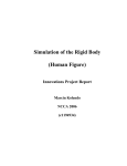
Mechanisms mainly consist of spur gears
Music boxes were developed in the
1800s. They appeared in a period
where mechanisms had advanced quite
a bit since the basic pendulum clock.
Looking closely at a musical
movement (the part of the music box
that creates music), one may notice
that spur gears are again the most used
but that there also spur gears with
perpendicular teeth (bevelled gear). 1
1
T.IL. Productions, 2001. Music boxes, The androids and automatons website [online]. Available
from: http://www.automates-anciens.com/english_version/ [Accessed 14/03/07].
4 / 31
Adrien Saint Girons
Innovations Report
cogs_v01
At this point, I had determined that I could create mechanisms of the required
complexity by using two different gear types. I would need to create spur gears that
could share the same rod or interlock with each other. They would also need to have
the option of being perpendicular to their parent. What’s more, the look of the gears
would need to vary. As spur gears are the most used and the most basic it was
essential to correctly understand the way the work.
Spur gear maths
Spur gears are used in machinery as they are the most efficient way to modify a
rotational source of power. They are most commonly used for changing the direction
of rotation, changing the speed of rotation, or changing the axis of rotation. The
increase or decrease of speed is given by the gear ratio. This ratio can be found by a
comparison of the number of teeth of two interlocked gears. If a gear A has 20 teeth
(tA) and is connected to another gear B that has 10 teeth (tB), the ratio is 2:1. This
means that the second gear will turn twice as fast as the first in the opposite direction.
The rotation of gear B (rB) is calculated by multiplying the negative of the rotation of
gear A (rA) by the ratio. 2
The ratio is given by:
The rotation of gear B is given by:
These simple equations give us an understanding of the relationship that exists
between two existing gears. However, it is essential to understand how to add new
gears to existing gears and ensure that they interlock correctly. The most efficient way
of doing this is by making the child’s teeth the same as its parent’s. In order to
determine the width of a gear’s tooth we must use its base circle’s radius and some
simple trigonometry.
We now know that the size of a tooth is directly related to the amount of teeth and by
the radius. It is essential that the ratio between the child and parent’s base radius is the
same as the ratio between the child and parent’s teeth. Therefore, the child base radius
is given by:
A gear that has no parent can be determined in knowledge of the amount of teeth and
the base radius. If a gear has a parent, we can find its base radius by using the amount
of teeth the parent has and the amount of teeth that it has.
2
STOKES, A., 1970. High performance gear design. Brighton: Machinery Publishing.
5 / 31
Adrien Saint Girons
Innovations Report
cogs_v01
Gear mathematics can be taken much further. In the engineering world there are other
factors that need to be taken into account. The physical contact between the teeth
requires mathematical precision in order to ensure maximal passage of energy. I
decided to leave such complex calculations out of this project because such precision
was not needed.
These equations would be the backbone of my code. All that was needed at this stage
was to create an appropriate implementation of spur gear interaction inside of Maya.
6 / 31
Adrien Saint Girons
Innovations Report
cogs_v01
Implementation of spur gears using mel script
My first attempt at implementing these concepts was very unstable and did not
produce the desired effect. This is mainly dude to the fact that I did not plan ahead. It
is very important to script in a methodical manner in order to limit the amount of
bugs.
The direction I took for the organisation of this code was to divide it into different
tasks. In order to keep it as interactive as possible all the variables are passed on to the
main procedure. It then calls the other procedures passing on the correct variables.
This makes it easier to know where to look while debugging.
The procedures are split into three main categories. One group takes care of drawing
the cogged wheels and their controls. Another makes sure that they interlock
correctly. The other procedures make sure that all the new objects are correctly
organised in the Maya workspace.
Drawing the gears
Gears are composed of mainly two different parts: the teeth and the body. Originally,
I made the gears by creating a cylinder of the correct amount of divisions and
extruding every other face of its edge. This was too expensive as it called the extrude
function and it was hard to know exactly where the teeth were placed. The easiest
solution was to keep the body and the teeth separate. This would enable me to have
full control of the body’s look and of the teeth’s placement.
Because of the nature of gears, especially in the world of clockwork, it is important to
be able to alter the geometry of the base and the teeth. Even though cogged wheels
may look alike, most clockmakers add a personal touch to the look of their gears. The
more attention is given to detail inside a clock, the better the clock. In order to keep
this aspect of clockwork in my script, the body’s look is determined by the $baseType
variable. Depending on its value, Maya will draw a complex or a simple base. The
same feature applies to the teeth with the variable $toothType. This logic enables me
or anyone else to go back to these procedures and add or change the look of the
cogged wheel. If these modifications are done sensibly, the gears would still work.
In order to make sure that that the logistics of the teeth’s interconnections worked, I
needed full control of the teeth’s placement. Creating the teeth by extruding the edges
made me very confused because the first tooth’s position was hard to determine. It is
essential to know where the tooth that will interlock is placed. I decided that this tooth
7 / 31
Adrien Saint Girons
Innovations Report
cogs_v01
would be at the bottom of the gear in the Z axis. The others are duplicates of the
original and are rotated by an angle determined by:
The next problem that arose at this stage was UV mapping and texturing the gears.
This tool aims to create an unlimited amount of functioning gears. To manually UV
map and texture every gear would have been a great loss of time and goes against the
point of this project. I felt it necessary to deal with this problem procedurally. During
my research, I realised that two different types of materials were used in old clock
work. The bigger wheels were made of brass and the smaller ones, known as pinions,
were made of steel. What’s more, these objects are made by cutting out circles from
sheets of the correct metal and carving in the teeth. Adopting a similar procedure in
Maya helped me texture the wheels in an efficient manner.
I created two brass sheet textures and two steel sheet textures instead of one texture
per gear. One texture per wheel would slow down Maya and the render time
tremendously. After having understood how to create these textures using mel script, I
needed to find a way to UV map and place these maps correctly on the metal sheets.
Because the gears were drawn as separate objects, I first needed to write a procedure
that would combine the geometry. The script then creates a planar mapping of the
gear, scales it accordingly, and places it randomly on one of the two sheets of the
chosen metal. Proceeding this way enabled me to create an interesting amount of
variation of the gear’s textures and saves the user a significant amount of time.
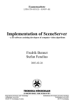
The metal sheet’s texture files
Automatic UV mapping example
8 / 31
Adrien Saint Girons
Innovations Report
cogs_v01
Getting it all to connect
Using the above procedures, I could now draw and texture cogwheels of different
types. I also had exact knowledge of each tooth’s placement. However, two essential
aspects were missing: the interaction between gears and the positioning of the gears.
The first step was figuring out a valid system that would answer to the user’s needs.
The teeth should connect correctly; the child wheel must be placed interactively in a
constrained manner by the user; the rotation of all wheels in a chain should be
determined by keying only one.
These constraints in mind, it was important to make a distinction between the gears
that would control the rotation of the gear chain and those that would be constrained
to their parent. In order to differentiate these gears at creation time, a procedure
checks if another wheel is selected. If this is the case, the selected wheel becomes
parent of the new wheel. If nothing is selected, the new wheel has no constraints and
can turn freely. Other gears can be attached to it by selecting it before calling the main
procedure.
Despite the gear being free or constrained, a series of controls were necessary in order
to modify the geometry’s rotation and translation. I thought it important to keep the
geometry and the ‘rigging’ as two separate aspects. And so the geometry is attached to
its controls and the logical constraints are applied to the controls. Each gear is given
two controls; one takes care of the gear’s rotation about its own axis (named
rotationControl) and the other gives the user the possibility of rotating the wheel
about its parent’s axis (named mainControl). If the wheel has no parent then the
mainControl acts as a rotational offset. The wheel is parented to the rotationControl
which is parented to the mainControl. The mainControl is parented to an empty group
that is point constrained to the parent (if the gear is a child). This parenting system
ensures a correct rotation of the gears.
rotationControl selected
mainControl selected
The next major step was to make sure that the gear’s teeth connected correctly. In
order to overcome this challenge, I used expressions. If a gear is at the head of a chain
or free, then no expression is attached to it. However, if a gear has a parent then an
expression is added to its rotation control. In order to achieve the final expression, I
needed to start from the basics and develop from there. As explained above, a gear’s
rotation in relationship to its parent is given by:
9 / 31
Adrien Saint Girons
Innovations Report
cogs_v01
In mel script we get:
cog_2_rotateControl.rotateY = -cog_1_rotateControl.rotateY*(cog_1.teeth/cog_2.teeth);
In the context of this tool, other factors must be taken into account. The fact that an
extra rotation exists about the parent’s axis (mainControl) leads to teeth intersection.
It is therefore important to add a value to the expression in order to annul this
rotation’s effect. Multiplying the mainControl’s rotational value by the ratio and
adding it to the above equation achieves the desired effect. The expression is now
given by:
cog_2_rotateControl.rotateY = -cog_1_rotateControl.rotateY*(cog_1.teeth/cog_2.teeth
+cog_2_mainControl.rotateY*(cog_1.teeth/cog_2.teeth);
Unfortunately this does not completely solve the problem of intersecting teeth. This
intersection happens when two even numbered gears are connected because of the
way the teeth are placed around the wheel’s base. Odd numbered gears do not have
this problem. To solve this, an offset is needed of the tooth’s width, giving the
following expression:
cog_2_rotateControl.rotateY = -cog_1_rotateControl.rotateY*(cog_1.teeth/cog_2.teeth)
+cog_2_mainControl.rotateY*(cog_1.teeth/cog_2.teeth)
+(180.0/cog_2.teeth);
The problem now resides in connecting odd and even gears together. An intersection
still occurs! I needed to find a way to make sure that this offset was not added if the
parent cogwheel was odd. The following equation returns 0 if the parent is odd and -1
if the parent is even: (cog_1.teeth % 2.0)-1)
Multiplying it by the offset solves our problem and gives us the final expression:
cog_2_rotateControl.rotateY = -cog_1_rotateControl.rotateY*(cog_1.teeth/cog_2.teeth)
+cog_2_mainControl.rotateY*(cog_1.teeth/cog_2.teeth)
+(180.0/cog_2.teeth)*(cog_1.teeth % 2.0)-1);
At this point, the script conducts quite a few calculations using both child and parent
information. If the naming is incorrect then the calculations are false or the program
does not work. It was very important to keep things well organised in the Maya
workspace.
10 / 31
Adrien Saint Girons
Innovations Report
cogs_v01
Keeping things tidy
Generating such a large amount of objects and data can quickly become messy. A user
needs to be able to control his workspace. Adding confusing information does not
help the programmer or the user and can work against the tool. Very early in the
developing stages, I realised that organising was essential as I kept getting naming
errors.
Naming in Maya is tricky because depending on where an object is placed
hierarchically it can have the same name as another object. What actually happens is
that Maya adds the hierarchy to the object’s name linking every part with the “|”
symbol. However, if you make sure that the name does not exist, then the object will
be referred to without the hierarchy attached to it. Keeping things this way makes
programming in mel a lot easier.
Making a naming convention was very useful. I decided to add “cog_” in front of
every object created by the script to differentiate them from the other objects in the
scene. When a new gear is created, a series of objects are associated to it. It only
makes sense to give a gear an ID number that is passed on to its objects. In order to
find this number, the following procedure checks the existence of a gear. If it exists, it
adds one to the ID number and tries again until it finds a number that hasn’t been
used.
proc int cog_number()
{
int $counter = 1;
string $current_Name = "cog_"+$counter;
while(`objExists $current_Name`){
$counter++;
$current_Name = "cog_"+$counter;
}
return $counter;
}
This technique gives me the assurance me that there will never be two of the same
objects. Now that the objects are named correctly, it is nice to have them organised
accordingly. Two groups get created (if they are not already there), one for the
geometry and one for the controls. Objects are placed correctly within these groups. In
order to keep the link between the geometry and the controls, a parent constraint is set
between the rotationControl and the gear geometry. This works nicely, yet it is easy to
select the geometry by mistake while trying to select a control. And so, two layers are
created (if they are not already created). The controls are placed in one layer and the
geometry in the other layer that is set to reference mode which ensures that the
geometry will not be selected.
Before creating a new gear, the script checks if any gear or control is selected. The
following procedure tries to find the parent’s ID. If nothing or an incorrect object is
selected then the procedure returns 0, the gear will have no parent. If a correct object
is selected, the procedure will extract the number from the selected objects name and
return it as the parent ID.
11 / 31
Adrien Saint Girons
Innovations Report
cogs_v01
proc int parent_number()
{
string $all_Selected[] = `ls -sl`;
string $split[];
}
if($all_Selected[0] == "" || `match "cog_" $all_Selected[0]` != "cog_"){
return 0;
}
else{
tokenize($all_Selected[0], "_", $split);
return $split[1];
}
Now that we have retrieved the parent ID, there needs to be a way to retrieve
information about the gear. This is dealt with by adding attributes to each gear.
Information about a gear’s teeth, radius, and so on, are stored and retrieved as the
gear’s attributes. This enables information to be retrieved simply in the procedures
and in the expressions.
The last important aspect of this part of the script is limiting the user’s options. The
gears are placed parallel to a particular plane and therefore rotate about a particular
axis. The user can choose where to place a gear around its parent’s axis. It is very
important that the user does not rotate in the incorrect axis. And so it is essential to
lock and hide every rotational axis apart from the desired one (in this case Y). This
constraint actually creates a very nice feature because the rotation tool becomes
extremely easy to use. The user can try to move it in any direction but it will always
turn correctly. Almost all attributes of the geometry are locked as they should not be
modified after creation.
12 / 31
Adrien Saint Girons
Innovations Report
cogs_v01
Developing the script further
The above implementation created interesting mechanisms. However, it did not
enable me to create machinery of the desired complexity. In order to make sure the
script would produce what I needed, I had to add new gear types, add a user interface
and test the script by creating a functioning clock.
Creating new gear types
Looking more closely at clockwork and music boxes, I noticed two things. First, it is
very common for two gears to share the same rod and rotate at the same rate. Second,
as explained earlier, there is a need for spur gears with perpendicular teeth. Now that
the framework of the script was set, implementing a new gear meant adding a variable
($connectionType) and checking its value when appropriate. The different types are:
interlocked, parallel, bevelled and inner gears.
Interlocked
Parallel
Bevelled
Inner
Interlocked, parallel and inner gears are created using the procedures described above.
The difference lies in the placement and the expression. The parallel gear is placed at
its parent’s position. It is up to the user to move it along the Y axis to the desired
height. The expression is very simple in this case; the child’s rotation is equal to the
parent’s rotation, giving us:
cog_2_rotateControl.rotateY = cog_1_rotateControl.rotateY;
An important feature in clockwork is the fact that the brass wheel includes a steel
pinion (gear) that fits in its inner circle. This inner gear can be implemented using the
same logic as the parallel gear. Extra calculations are necessary for the inner gear’s
radius and placement. The radius can be calculated by subtracting the tooth’s depth
from the parent’s inner radius. If one wishes the parent and the child to have the same
type of teeth, then the amount of teeth can be determined with the following
calculation. The radius is figured out based on the number of teeth.
int $teeth = (($parent_innerRadius - $depth)*$parent_teeth)/$parent_radius;
A rod is needed in order to connect parallel gears to their parents. This rod is created
only if the parent does not already have one. It is placed along the gear’s rotational
axis. The rod can then be translated along this axis and scaled by the user.
The bevelled gear has an entirely different implementation. First of all, they are drawn
in a different way to the other gears. In order to ensure a correct implementation of the
bevelled gear, it was important to keep the drawing similar to that of the spur gears.
The radius of the bevelled gear is determined by adding the tooth height to the base
13 / 31
Adrien Saint Girons
Innovations Report
cogs_v01
radius. The teeth are then placed above the base in the same way as spur gears but
pointing upwards.
In order to make sure that the teeth do not intersect, the original expression can be
used. All that needs to be taken care of is rotating the controls and moving their pivots
correctly.
The tool can now create the type of gears needed. However, calling the main
procedure may seem tricky to some.
Making a GUI
In order to call the main procedure, the user is asked to pass on a list of 12 arguments.
They are: radius, height, teeth, depth, connection type, base type, tooth type, inner
radius, texture file, the ‘same teeth’ option, rod type and divisions. It would be very
hard for the user to remember all of these arguments and to place them correctly. I
was having a hard time myself getting the order right. A GUI would help make more
sense of the tool.
My first attempt in the creation of the GUI was unsuccessful. I made three sections
aiming to make the arguments more clear. The first section covered the connection
type of the gear. The second and third parts gave options to change the teeth and the
body of the gear. Finally the last section asked the user what action to take (add, edit,
delete). I asked a few people to try the GUI and the tool but they were very quickly
confused. The way I had organised the GUI was far too complex. By trying to
simplify things I had managed to complicate them.
Original GUI
I then decided to go back to the way I originally called the main procedure. The script
is such that once it has finished, it selects the gear’s mainControl. By creating another
14 / 31
Adrien Saint Girons
Innovations Report
cogs_v01
gear straight away you are in fact connecting it to the one created before. In this
manner, it is very easy to create a gear chain. This was a technique I regularly used
while programming to test the tool.
cog_create(3.0, .25, 50, .2, 1, 2, 2, .5, 1, 1, 0, 20);
cog_create(3.0, .25, 40, .2, 1, 2, 2, .5, 1, 1, 0, 20);
cog_create(3.0, .25, 30, .2, 1, 2, 2, .5, 1, 1, 0, 20);
Implementing this concept in the GUI seemed like a good idea as it would enable the
user to create a complex chain by clicking on one button. This time the GUI is
separated in three parts. The first part determines how many gears to add to the chain.
The minimal amount is set to 1 and maximum to 50. Changing this value adds or
removes a line from the second part of the GUI. In the second part there is a line for
every gear that will be created. Each line corresponds to a list of a specific gear’s
arguments. The user can change each gear’s arguments by modifying any of the
values. In order to help the user further, some values are automatically changed when
the connection type value is modified. This is useful particularly for inner gears that
tend to have a greater heights and steel as a material. The final part of this GUI
corresponds to a button that creates the gear chain or adds it to a selected gear.
The latest GUI
So when the tool became easier to use, it was time to see if it worked correctly by
testing it.
Clock making in Maya
The best way to test a tool that generates clockwork orientated gears is by making a
functioning clock. I was lucky in the sense that most of my research was based around
clocks so I had already read explanations of clocks during my research. What’s more,
I had befriended a clockmaker in the outskirts of Paris who was happy to answer my
questions.3 One thing he made very clear to me however was that clockwork had gone
a very long way and that there was no way that I would understand modern clockwork
in such a small amount of time. He then orientated me towards older pendulum type
clocks known as comtoise clocks. These magnificent clocks were developed in the
3
LAYET, P., 2007. Horlogerie Patrick Layet
http://www.horlogerie.new.fr [Accessed 14/03/07].
15 / 31
Creations
[online].
Available
from:
Adrien Saint Girons
Innovations Report
cogs_v01
1800s and could tell the month, the hour, the minute and the second.4 I was happy to
create a clock that would tell only the hour and the minute.
Pendulum clocks work by using two sources of energy. On one hand the pendulum
rotates back and forth permitting the escapement gear to advance a little every second.
This movement drives the whole gear chain and rotates the hour hand and the minute
hand accordingly. The problem however is that the pendulum looses momentum and
eventually stops rotating. A weight or a spring is added to the mechanism which adds
an extra force and helps the pendulum rotate. Once the weight has dropped
completely or the spring fully unwound then the clock must be rewound and reset.5
The way the gears are supposed to be connected inside a clock is not so easy to figure
out. I came across a site that explained how to make wooden clocks out of wooden
gears. This proved to be very useful as I found information about the exact number of
teeth needed per gear and how to connect them together. With all of this information
as well as the gear generating tool, the creation of the chain was very straightforward.
Adding a face to the clock and correctly parenting an hour and a minute hand proved
that the gears where working correctly.
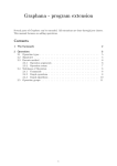
The escapement (30 t) does one full rotation in
60 seconds.
The ratio between the escapement gear and the
minute gear (90 t) is 1:60 given by:
The ratio between the minute gear and the hour
gear (48 t) is 1:12 given by:6
In order to get the seconds working, I added a pendulum that would drive the chain.
The pendulum goes from one side to another in one second (25 frames). In that
movement the escapement will rotate by one tooth. This means that in 60 seconds, the
escapement would have made one full rotation. The way this is implemented is by
using an expression and adding an “open” attribute to the pendulum. The expression
checks if the escapement can advance, if so then it advances accordingly. If it is
closed then it stays put.
4
CAUDINE, L., 1998-2005. Les horloges comtoise anciennes [online]. Available from:
http://perso.orange.fr/comtoise.caudine/index.htm [Accessed 14/03/07].
5
BRAIN, M., 1998-2007. Howstuffworks “How Pendulum Clocks Work” [online]. Available from:
http://www.howstuffworks.com/clock.htm [Accessed 14/03/07].
6
MAHONY,
G.,
2006.
Gary’s
wooden
clocks
[online].
http://www.pathcom.com/~u1068740/index.html [Accessed 14/03/07].
16 / 31
Available
from:
Adrien Saint Girons
Innovations Report
cogs_v01
if (pCylinder1.open)
cog_1_rotateControl.rotateY = cog_1_rotateControl.rotateY - .52083;
front view
back view
Now that we have a working clock, why not set it to the correct time? In order to do
so, I used the “date” function to retrieve information about the time and created a
button that would move the hands to the correct time and then start the clock.
This clock works when the playback is at 25 frames per second. If the animation was
rendered than it would tell time correctly. However rendering out the clock would not
give us the current time. This should not be a problem if we could set and run the
clock at 25 fps in Maya. Unfortunately, Maya cannot keep a constant frame rate.
When asked to play at 25 frames per second the clock works a little too slowly. If
Maya is the only program open then the clock looses about 2 minutes in an hour.
Unfortunately this frame loss is not constant and cannot be foreseen. There is no real
solution to this problem apart from resetting the clock every so often. In order to reset
the clock back to the correct time all one needs to do is click on the reset button.
17 / 31
Adrien Saint Girons
Innovations Report
cogs_v01
Conclusion
Overall, this tool has reached an interesting stage. It draws clockwork orientated gears
of different types and constrains them in a logical manner which imitates the way they
work in real life. I am pleased with the final result as it answers most of my
expectations.
There are certain aspects that I would like to improve in the future however. The fact
that I was developing this tool for my Major Project was good because it helped me
focus on specific problems that needed to be solved. However, as much as I wanted
the tool to be easy to use, the fact that I was writing the tool primarily for myself did
not help. I know how to use the tool very well because I can work around its
limitations. In order to make this tool more user-friendly I would need to solve the
following limitations:
-The user can change a gear’s value to an extent that it will not look correct
-The file paths must be entered manually in the script
-If a gear is deleted, connections need to be mended manually
-Gears cannot be edited
At present these factors work against the tool. Solving the above would enable the
tool to be used by anyone and ensure that no bug would occur. One can imagine
taking this project much further and implement modern clockwork. Watch companies
could then in theory use it to create new watch designs.
This challenging project opened my eyes to the world of tool writing. The amount of
motivation I had while I was developing this tool made me realise how much I enjoy
this aspect in 3D animation. I hope that my future career will allow me to further
develop this skill.
References
BRAIN, M., 1998-2007. Howstuffworks “How Pendulum Clocks Work” [online].
Available from: http://www.howstuffworks.com/clock.htm [Accessed 14/03/07].
CAUDINE, L., 1998-2005. Les horloges comtoise anciennes [online]. Available
from: http://perso.orange.fr/comtoise.caudine/index.htm [Accessed 14/03/07].
LAYET, P., 2007. Horlogerie Patrick Layet Creations [online]. Available from:
http://www.horlogerie.new.fr [Accessed 14/03/07].
MAHONY, G., 2006. Gary’s wooden clocks [online]. Available
http://www.pathcom.com/~u1068740/index.html [Accessed 14/03/07].
from:
STOKES, A., 1970. High performance gear design. Brighton: Machinery Publishing.
T.IL. Productions, 2001. Music boxes, The androids and automatons website [online].
Available from: http://www.automates-anciens.com/english_version/ [Accessed
14/03/07].
18 / 31
Adrien Saint Girons
Innovations Report
cogs_v01
Appendix 1: cogs_v01 source code
////////////////////////////////////////////////////////////////////////////////
// Name: cogs_v01
//
// Author: Adrien Saint Girons
//
// Date: 14/03/07 17:38
//
// Description: This tool is a clockwork-like gear generator.
//
//
//
// Installation: First, make sure the file paths are correct bellow
//
//
Run the script in the script editor.
//
//
Use the user manual for more information.
//
//
//
// NOTE: run "cog_UI()" in script editor if window does not apear.
//
////////////////////////////////////////////////////////////////////////////////
/////////////////////////// ! ! ! WARNING ! ! ! ////////////////////////////////
//////////////// !!! PLEASE ENTER CORRECT FILE PATHS !!! //////////////////////
////////////////////////////////////////////////////////////////////////////////
proc cog_UserMan()
{
showHelp -absolute "D:/cogs_v01/User_Manual.htm";
//User_Manual.htm
}
/////////////////////////// ! ! ! WARNING ! ! ! ////////////////////////////////
////////////////////////////////////////////////////////////////////////////////
proc cog_create(float $radius, float $base_height, float $teeth, float $depth,
int $connectionType, int $baseType, int $toothType, float $innerRadius,
int $texture, int $sameTeeth, int $rodType, float $divisions)
{
/////////////////////////// ! ! ! WARNING ! ! ! ////////////////////////////////
//////////////// !!! PLEASE ENTER CORRECT FILE PATHS !!! //////////////////////
////////////////////////////////////////////////////////////////////////////////
string
string
string
string
$brassFile1
$brassFile2
$steelFile1
$steelFile2
=
=
=
=
"D:/cogs_v01/textures/brass1.jpg";
"D:/cogs_v01/textures/brass2.jpg";
"D:/cogs_v01/textures/steel1.jpg";
"D:/cogs_v01/textures/steel2.jpg";
//brass1.jpg
//brass2.jpg
//steel1.jpg
//steel2.jpg
/////////////////////////// ! ! ! WARNING ! ! ! ////////////////////////////////
////////////////////////////////////////////////////////////////////////////////
int $cog_ID = cog_number();
int $parent_ID = parent_number();
string $base_name = ("cog_" + $cog_ID);
string $rotateControl_name = $base_name + "_rotateControl";
string $mainControl_name = $base_name + "_mainControl";
string $controlGroup = $base_name + "_controls";
if ($connectionType == 4 && $sameTeeth == 1)
$teeth = relative_teeth($parent_ID, $depth);
if ($connectionType == 4 && $sameTeeth == 0)
$radius = relative_radius($parent_ID, $depth);
else if ($parent_ID != 0 && $sameTeeth == 1)
{
$radius = radius($parent_ID, $teeth);
$depth = `getAttr ("cog_" + $parent_ID +".depth")`;
}
19 / 31
Adrien Saint Girons
Innovations Report
cogs_v01
float $width = width($radius, $teeth);
float $tooth_height = $base_height;
layers();
draw_base($radius , $base_height, $tooth_height, $divisions, $base_name,
$connectionType, $baseType, $innerRadius);
draw_teeth($teeth, $width, $base_height, $tooth_height, $depth, $radius,
$base_name, $connectionType, $toothType);
cog_finalise($teeth, $base_name);
textures($base_name, $radius, $texture, $brassFile1, $brassFile2,
$steelFile1, $steelFile2);
draw_control(($radius/2), $base_height, $rotateControl_name,
$mainControl_name, $controlGroup, $base_name, $parent_ID);
groups($base_name,$controlGroup);
add_attributes($base_name, $parent_ID, $teeth, $width, $depth,
$connectionType, $tooth_height, $base_height, $radius, $innerRadius,
$rodType);
expressions($base_name, $depth);
lock_attributes($base_name);
makeRod($base_name, $parent_ID, $rodType, $connectionType);
}
select -r $mainControl_name;
proc int cog_number()
{
int $counter = 1;
string $current_Name = "cog_"+$counter;
while(`objExists $current_Name`){
$counter++;
$current_Name = "cog_"+$counter;
}
return $counter;
}
proc int parent_number()
{
string $all_Selected[] = `ls -sl`;
string $split[];
if($all_Selected[0] == "" || `match "cog_" $all_Selected[0]` != "cog_"){
return 0;
}
else{
tokenize($all_Selected[0], "_", $split);
return $split[1];
}
}
proc float width(float $radius, float $teeth)
{
float $angle = deg_to_rad ((360.0/$teeth)/8.0);
float $width = (sin($angle)*$radius)*4.0;
return $width;
}
proc float radius(int $parent_ID, float $teeth)
{
float $parent_teeth = `getAttr ("cog_"+$parent_ID+".teeth")`;
float $parent_radius = `getAttr ("cog_"+$parent_ID+".radius")`;
20 / 31
Adrien Saint Girons
Innovations Report
cogs_v01
float $radius = ($teeth/$parent_teeth)*$parent_radius;
return $radius;
}
proc float relative_teeth(int $parent_ID, float $depth)
{
float $parent_innerRadius = `getAttr ("cog_"+$parent_ID+".innerRadius")`;
float $parent_teeth = `getAttr ("cog_"+$parent_ID+".teeth")`;
float $parent_radius = `getAttr ("cog_"+$parent_ID+".radius")`;
int $teeth = (($parent_innerRadius - $depth)*$parent_teeth)/$parent_radius;
return ($teeth+1);
}
proc float relative_radius(int $parent_ID, float $depth)
{
float $parent_innerRadius = `getAttr ("cog_"+$parent_ID+".innerRadius")`;
float $radius = $parent_innerRadius - $depth;
return $radius;
}
proc draw_base(float $radius, float $height, float $tooth_height,
float $divisions, string $base_name, int $connectionType, int $baseType,
float $innerRadius)
{
if ($baseType == 1)
polyCylinder -r 1 -h 1 -sx $divisions -n $base_name;
else if ($baseType == 2)
{
int $innerDivisions = $divisions/1.25;
polyPipe -r 1 -h 2 -t .15 -sa $divisions -sh 1 -sc 0 -ax 0 1 0 -cuv 1
-rcp 0 -ch 1 -n ($base_name+"part1");
polyPipe -r .4 -h 2 -t (.4*(1-$innerRadius)) -sa $innerDivisions -sh 1
-sc 0 -ax 0 1 0 -cuv 1 -rcp 0 -ch 1 -n ($base_name+"part2");
polyCube -w .25 -h 1 -d .6 -sx 1 -sy 1 -sz 1 -ax 0 1 0 -cuv 4 -ch 1
-n ($base_name+"part3");
setAttr ($base_name+"part3.translateZ") .6;
move -r 0 0 (-.6) ($base_name+"part3.scalePivot")
($base_name+"part3.rotatePivot");
duplicate -rr; rotate -r 0 90 0;
for ($i=0; $i<2; $i++) duplicate -rr -st;
group -n $base_name ($base_name+"part1") ($base_name+"part2")
($base_name+"part3") ($base_name+"part4") ($base_name+"part5")
($base_name+"part6");
}
if ($connectionType == 3)
setAttr ($base_name+".scale") ($radius+$tooth_height)
$height ($radius+$tooth_height);
else
setAttr ($base_name+".scale") $radius $height $radius;
}
proc draw_teeth(float $teeth, float $width, float $base_height, float $height,
float $depth, float $base_radius, string $base_name, int $connectionType,
int $toothType)
{
string $tooth_name = $base_name + "_tooth_1";
polyPlane -w 1 -h 1 -sx 1 -sy 1 -ax 1 0 0 -cuv 2 -ch 1 -n $tooth_name;
setAttr ($tooth_name+".scale") 0 $height $width;
if($toothType == 1)
polyExtrudeFacet -constructionHistory 1 -ltz ($depth+($depth/2.0))
21 / 31
Adrien Saint Girons
Innovations Report
cogs_v01
-lsy .6 -smoothingAngle 30 ($tooth_name+".f[0]");
else if($toothType == 2)
{
polyExtrudeFacet -constructionHistory 1 -ltz ($depth) -lsy .9
-smoothingAngle 30 ($tooth_name+".f[0]");
polyExtrudeFacet -constructionHistory 1 -ltz ($depth/2.0) -lsx .6
-smoothingAngle 30 ($tooth_name+".f[0]");
}
makeIdentity -apply true -t 1 -r 1 -s 1 -n 0;
if ($connectionType == 3)
{
setAttr ($tooth_name+".translateX") ($base_radius+($height/2.0));
setAttr ($tooth_name+".rotateZ") 90;
setAttr ($tooth_name+".translateY") (($base_height/2.0)-($depth/2.0));
move -r (-($base_radius+($height/2.0))) 0 0 ($tooth_name+".scalePivot")
($tooth_name+".rotatePivot");
makeIdentity -apply true -t 1 -r 1 -s 1 -n 0;
setAttr ($tooth_name+".rotateY") -90;
}
else
{
setAttr ($tooth_name+".translateX") ($base_radius-($depth/2.0));
move -r (-$base_radius+($depth/2.0)) 0 0 ($tooth_name+".scalePivot")
($tooth_name+".rotatePivot");
setAttr ($tooth_name+".rotateY") -90;
}
parent $tooth_name $base_name;
float $angle = 360.0/$teeth;
duplicate -rr; rotate -r 0 $angle 0;
for ($i=2; $i<$teeth; $i++) duplicate -rr -st;
}
proc cog_finalise(float $teeth, string $base_name)
{
select -hi $base_name;
string $all_Objects[] = `ls -sl`;
polyUnite -ch 1 -n "newObject" $all_Objects ;
delete -ch newObject;
rename newObject $base_name;
}
proc draw_control(float $radius, float $height, string $rotateControl_name,
string $mainControl_name, string $controlGroup, string $base_name,
int $parent_ID)
{
curve -d 3 -p -5.95856e-008 0 -1.999361 -p -5.95856e-008 0 -1.999361
-p -1.575813 0 -1.575813 -p -2.228535 0 0 -p -1.575813 0 1.575813
-p 0 0 1.999361 -p 0 0 1.999361 -p 0 0 1.999361 -p -0.00319036 0 2.275362
-p -0.00319036 0 2.275362 -p -0.00319036 0 2.275362 -p 1.179168 0 1.592934
-p 1.179168 0 1.592934 -p -0.00319045 0 0.910506 -p -0.00319045 0 0.910506
-p 1.78757e-007 0 1.199616 -p 1.78757e-007 0 1.199616
-p -0.937525 0 0.937525 -p -1.32586 0 0 -p -0.937525 0 -0.937525
-p -2.97928e-008 0 -1.199616 -p -2.97928e-008 0 -1.199616
-p -2.97928e-008 0 -1.199616 -p -0.00319045 0 -0.910782
-p -0.00319045 0 -0.910782 -p 1.179168 0 -1.593417 -p 1.179168 0 -1.593417
-p -0.00319036 0 -2.276052 -p -0.00319036 0 -2.276052
-p -5.95856e-008 0 -1.999361 -p -5.95856e-008 0 -1.999361 -p -5.95856e-008 0
-1.999361 -k 0 -k 0 -k 0 -k 1 -k 2 -k 3 -k 4 -k 5 -k 6 -k 7 -k 8 -k 9 -k 10
-k 11 -k 12 -k 13 -k 14 -k 15 -k 16 -k 17 -k 18 -k 19 -k 20 -k 21 -k 22
22 / 31
Adrien Saint Girons
Innovations Report
cogs_v01
-k 23 -k 24 -k 25 -k 26 -k 27 -k 28 -k 29 -k 29 -k 29 -n $mainControl_name;
setAttr ($mainControl_name+".scale") ($radius/2.0) 1 ($radius/1.5);
setAttr ($mainControl_name+".rotateY") -90;
makeIdentity -apply true -t 1 -r 1 -s 1 -n 0;
setAttr ($mainControl_name+".translateY") ($height+.5);
move -r 0 (-($height+.5)) 0 ($mainControl_name+".scalePivot")
($mainControl_name+".rotatePivot") ;
curve -d 3 -p 0 0 0 -p 0 0 -3 -p 0 0 -3 -p 0 0 0 -p -1 0 -1 -p -1 0 -1
-p 0 0 0 -p -3 0 0 -p -3 0 0 -p 0 0 0 -p -1 0 1 -p -1 0 1 -p 0 0 0 -p 0 0 3
-p 0 0 3 -p 0 0 0 -p 1 0 1 -p 1 0 1 -p 0 0 0 -p 3 0 0 -p 3 0 0 -p 3 0 0
-p 0 0 0 -p 1 0 -1 -p 1 0 -1 -p 0 0 0 -p 0 0 -3 -p 0 0 -3 -p 0 0 -3 -k 0
-k 0 -k 0 -k 1 -k 2 -k 3 -k 4 -k 5 -k 6 -k 7 -k 8 -k 9 -k 10 -k 11 -k 12
-k 13 -k 14 -k 15 -k 16 -k 17 -k 18 -k 19 -k 20 -k 21 -k 22 -k 23 -k 24
-k 25 -k 26 -k 26 -k 26 -n $rotateControl_name;
setAttr ($rotateControl_name+".scale") ($radius/2.0) 1 ($radius/2.0);
setAttr ($rotateControl_name+".translateY") ($height+.5);
move -r 0 (-($height+.5)) 0 ($rotateControl_name+".scalePivot")
($rotateControl_name+".rotatePivot") ;
if ($parent_ID != 0)
setAttr ($rotateControl_name+".visibility") off;
else
setAttr ($mainControl_name+".scale") 0 0 0;
}
group -em -n $controlGroup;
parent $rotateControl_name $mainControl_name;
parent $mainControl_name $controlGroup;
parentConstraint -mo $rotateControl_name $base_name;
proc makeRod(string $base_name, int $parent_ID, int $rodType,
int $connectionType)
{
int $parentRod = 1;
if ($parent_ID != 0 && $connectionType != 1)
$parentRod = `getAttr ("cog_"+$parent_ID+".rodType")`;
if ($parentRod == 1 && $rodType != 1)
{
float $radius;
if ($rodType == 2)
$radius = `getAttr ($base_name+".innerRadius")`;
if ($rodType == 3)
$radius = `getAttr ($base_name+".radius")`;
polyCylinder -r $radius -h 10 -sx 20 -n ($base_name+"_Rod");
parentConstraint $base_name ($base_name+"_Rod");
}
}
proc layers()
{
if (`objExists cog_Geometry_Layer` == 0){
createDisplayLayer -empty -name "cog_Geometry_Layer";
layerEditorLayerButtonTypeChange "cog_Geometry_Layer";
layerEditorLayerButtonTypeChange "cog_Geometry_Layer";
}
if (`objExists cog_Controls` == 0){
createDisplayLayer -empty -name "cog_Controls_Layer";
}
}
23 / 31
Adrien Saint Girons
Innovations Report
cogs_v01
proc string textureFile(string $shader, string $textureFile)
{
string $fileName = $shader+"_file";
string $placeName = $shader+"_place2dTexture";
shadingNode -asTexture file -n $fileName;
shadingNode -asUtility place2dTexture -n $placeName;
connectAttr -f ($placeName+".coverage") ($fileName+".coverage");
connectAttr -f ($placeName+".translateFrame") ($fileName+".translateFrame");
connectAttr -f ($placeName+".rotateFrame") ($fileName+".rotateFrame");
connectAttr -f ($placeName+".mirrorU") ($fileName+".mirrorU");
connectAttr -f ($placeName+".mirrorV") ($fileName+".mirrorV");
connectAttr -f ($placeName+".stagger") ($fileName+".stagger");
connectAttr -f ($placeName+".wrapU") ($fileName+".wrapU");
connectAttr -f ($placeName+".wrapV") ($fileName+".wrapV");
connectAttr -f ($placeName+".repeatUV") ($fileName+".repeatUV");
connectAttr -f ($placeName+".offset") ($fileName+".offset");
connectAttr -f ($placeName+".rotateUV") ($fileName+".rotateUV");
connectAttr -f ($placeName+".noiseUV") ($fileName+".noiseUV");
connectAttr -f ($placeName+".vertexUvOne") ($fileName+".vertexUvOne");
connectAttr -f ($placeName+".vertexUvTwo") ($fileName+".vertexUvTwo");
connectAttr -f ($placeName+".vertexUvThree") ($fileName+".vertexUvThree");
connectAttr -f ($placeName+".vertexCameraOne")
($fileName+".vertexCameraOne");
connectAttr ($placeName+".outUV") ($fileName+".uv");
connectAttr ($placeName+".outUvFilterSize") ($fileName+".uvFilterSize");
setAttr -type "string" ($fileName+".fileTextureName") ($textureFile);
return $fileName;
}
proc textures(string $base_name, float $radius, string $texture, string
$textureFile1, string $textureFile2, string $textureFile3, string $textureFile4)
{
if (`objExists brass1` == 0){
shadingNode -asShader blinn -n brass1;
string $fileName =textureFile("brass1",$textureFile1);
connectAttr -f ($fileName+".outColor") brass1.color;
}
if (`objExists brass2` == 0){
shadingNode -asShader blinn -n brass2;
string $fileName =textureFile("brass2",$textureFile2);
connectAttr -f ($fileName+".outColor") brass2.color;
}
if (`objExists steel1` == 0){
shadingNode -asShader blinn -n steel1;
string $fileName =textureFile("steel1",$textureFile3);
connectAttr -f ($fileName+".outColor") steel1.color;
}
if (`objExists steel2` == 0){
shadingNode -asShader blinn -n steel2;
string $textureFile = "D:/Major_Project/textures/STEEL2.jpg";
string $fileName =textureFile("steel2",$textureFile4);
connectAttr -f ($fileName+".outColor") steel2.color;
}
int $switch = rand(1,2.9);
select -r $base_name;
if ($texture == 1)
hyperShade -assign ("brass"+$switch);
else if ($texture == 2)
hyperShade -assign ("steel"+$switch);
24 / 31
Adrien Saint Girons
}
Innovations Report
cogs_v01
int $numFaces[] = `polyEvaluate -f $base_name`;
int $numUVs[] = `polyEvaluate -v $base_name`;
float $uvRadius = $radius/10.0;
float $maxUV = .5-($uvRadius/2.0);
float $randU = rand ((-$maxUV),$maxUV);
float $randV = rand ((-$maxUV),$maxUV);
polyProjection -ch 1 -type Planar -ibd on -kir -md y
($base_name+"Shape.f[0:"+($numFaces[0]-1)+"]");
select -r ($base_name+"Shape.map[0:"+($numUVs[0]-1)+"]");
polyEditUV -pu 0.5 -pv 0.5 -su $uvRadius -sv $uvRadius ;
polyEditUV -u $randU -v $randV ;
proc groups(string $geometry, string $control)
{
if (`objExists cog_Geometry` == 0){
group -em -n "cog_Geometry";
}
if (`objExists cog_Controls` == 0){
group -em -n "cog_Controls";
}
parent $geometry cog_Geometry;
parent $control cog_Controls;
}
select -r cog_Geometry;
editDisplayLayerMembers -noRecurse cog_Geometry_Layer `ls -selection`;
select -r cog_Controls;
editDisplayLayerMembers -noRecurse cog_Controls_Layer `ls -selection`;
proc add_attributes(string $base_name, int $parent_ID, float $teeth,
float $width, float $depth, int $connectionType, float $tooth_height,
float $base_height, float $radius, float $innerRadius, int $rodType)
{
addAttr -ln teeth -k true -dv $teeth $base_name;
addAttr -ln width -k true -dv $width $base_name;
addAttr -ln depth -k true -dv ($depth*2.0) $base_name;
addAttr -ln toothHeight -k true -dv $tooth_height $base_name;
addAttr -ln baseHeight -k true -dv $base_height $base_name;
addAttr -ln radius -k true -dv $radius $base_name;
addAttr -ln innerRadius -k true -dv ((.4*$innerRadius)*$radius) $base_name;
addAttr -ln rodType -k true -dv $rodType $base_name;
if ($connectionType == 3)
setAttr ($base_name+".radius") ($radius+$tooth_height);
addAttr -ln parentID -k true -dv $parent_ID ($base_name+"_mainControl");
addAttr -ln connectionType -k true -dv $connectionType
($base_name+"_mainControl");
}
proc lock_attributes(string $base_name)
{
setAttr -lock true ($base_name+".tx");
setAttr -lock true ($base_name+".ty");
setAttr -lock true ($base_name+".tz");
setAttr -lock true ($base_name+".rx");
setAttr -lock true ($base_name+".ry");
setAttr -lock true ($base_name+".rz");
setAttr -lock true ($base_name+".sx");
25 / 31
Adrien Saint Girons
Innovations Report
cogs_v01
setAttr -lock true ($base_name+".sz");
setAttr
setAttr
setAttr
setAttr
setAttr
setAttr
setAttr
setAttr
-lock
-lock
-lock
-lock
-lock
-lock
-lock
-lock
true
true
true
true
true
true
true
true
-keyable false ($base_name+"_rotateControl.tx");
-keyable false ($base_name+"_rotateControl.ty");
-keyable false ($base_name+"_rotateControl.tz");
-keyable false ($base_name+"_rotateControl.rx");
-keyable false ($base_name+"_rotateControl.rz");
($base_name+"_rotateControl.sx");
($base_name+"_rotateControl.sy");
($base_name+"_rotateControl.sz");
setAttr
setAttr
setAttr
setAttr
setAttr
-lock
-lock
-lock
-lock
-lock
true
true
true
true
true
-keyable false ($base_name+"_mainControl.rx");
-keyable false ($base_name+"_mainControl.rz");
($base_name+"_mainControl.sx");
($base_name+"_mainControl.sy");
($base_name+"_mainControl.sz");
}
proc expressions(string $base_name, float $depth)
{
float $parent_ID = `getAttr ($base_name+"_mainControl.parentID")`;
if($parent_ID != 0){
float $connectionType =
`getAttr ($base_name+"_mainControl.connectionType")`;
float $parentType =
`getAttr ("cog_"+$parent_ID+"_mainControl.connectionType")`;
float $child_radius = `getAttr ($base_name+".radius")`;
float $parent_radius = `getAttr ("cog_"+$parent_ID+".radius")`;
float $base_height = `getAttr ($base_name+".baseHeight")`;
float $tooth_height = `getAttr ($base_name+".toothHeight")`;
float $p_base_height = `getAttr ("cog_"+$parent_ID+".baseHeight")`;
float $p_tooth_height = `getAttr ("cog_"+$parent_ID+".toothHeight")`;
string $expression_Name = ($base_name+"_Constraints");
if(`objExists $expression_Name` == 0){
expression -o $base_name -n $expression_Name;
}
if($connectionType == 1 && $parent_ID != 0){
if($parentType == 1 || $parentType == 2 || $parentType == 4)
{
float $pivotTranslate = $child_radius+$parent_radius+$depth;
move -r 0 0 $pivotTranslate
($base_name+"_mainControl.scalePivot")
($base_name+"_mainControl.rotatePivot") ;
move -r 0 0 $pivotTranslate ($base_name+"_controls.scalePivot")
($base_name+"_controls.rotatePivot") ;
pointConstraint -n ($base_name+"_link1")
("cog_"+$parent_ID+"_rotateControl") ($base_name+"_controls");
orientConstraint -n ($base_name+"_link2")
("cog_"+$parent_ID+"_mainControl") ($base_name+"_controls");
string $expression = ($base_name+"_rotateControl.rotateY = "
+$base_name+"_mainControl.rotateY*(cog_"+$parent_ID+".teeth/"
+$base_name+".teeth)+((180.0/"+$base_name+".teeth)*((cog_"
+$parent_ID+".teeth % 2.0)-1))-cog_"+$parent_ID
+"_rotateControl.rotateY*(cog_"+$parent_ID
+".teeth/"+$base_name+".teeth);\r\n");
expression -e -s $expression -o $base_name $expression_Name;
}
else if($parentType == 3)
26 / 31
Adrien Saint Girons
{
Innovations Report
cogs_v01
setAttr ($base_name+"_mainControl.rotateX") 90;
float $pivotTranslateZ = $parent_radius-($tooth_height/2.0);
float $pivotTranslateY =
-($child_radius+$depth+($p_base_height/2.0));
move -r 0 $pivotTranslateY $pivotTranslateZ
($base_name+"_mainControl.scalePivot")
($base_name+"_mainControl.rotatePivot") ;
move -r 0 $pivotTranslateY $pivotTranslateZ
($base_name+"_controls.scalePivot")
($base_name+"_controls.rotatePivot") ;
pointConstraint -n ($base_name+"_link1")
("cog_"+$parent_ID+"_rotateControl") ($base_name+"_controls");
orientConstraint -n ($base_name+"_link2")
("cog_"+$parent_ID+"_mainControl") ($base_name+"_controls");
string $expression = ($base_name+"_rotateControl.rotateY = "
+$base_name+"_mainControl.rotateY*(cog_"+$parent_ID+".teeth/"
+$base_name+".teeth)+((180.0/"+$base_name
+".teeth)*((cog_"+$parent_ID+".teeth % 2.0)-1))-cog_"
+$parent_ID+"_rotateControl.rotateY*(cog_"
+$parent_ID+".teeth/"+$base_name+".teeth);\r\n");
expression -e -s $expression -o $base_name $expression_Name;
}
}
else if($connectionType == 2 && $parent_ID != 0 || $connectionType == 4
&& $parent_ID != 0){
float $originalPosition = $base_height+.5+($base_height/2.0)
-($p_base_height/2.0)-.01;
setAttr ($base_name+"_mainControl.translateY") $originalPosition;
string $expression = ($base_name+"_rotateControl.rotateY = cog_"
+$parent_ID+"_rotateControl.rotateY;\r\n");
expression -e -s $expression -o $base_name $expression_Name;
pointConstraint -n ($base_name+"_link1")
("cog_"+$parent_ID+"_rotateControl") ($base_name+"_controls");
orientConstraint -n ($base_name+"_link2")
("cog_"+$parent_ID+"_mainControl") ($base_name+"_controls");
}
else if($connectionType == 3 && $parent_ID != 0 && $parentType != 3){
setAttr ($base_name+"_mainControl.rotateX") 90;
float $pivotTranslateZ = $parent_radius+$depth+($p_base_height/2.0);
float $pivotTranslateY = -($child_radius-($tooth_height/2.0));
move -r 0 $pivotTranslateY $pivotTranslateZ
($base_name+"_mainControl.scalePivot")
($base_name+"_mainControl.rotatePivot") ;
move -r 0 $pivotTranslateY $pivotTranslateZ
($base_name+"_controls.scalePivot")
($base_name+"_controls.rotatePivot") ;
pointConstraint -n ($base_name+"_link1")
("cog_"+$parent_ID+"_rotateControl") ($base_name+"_controls");
orientConstraint -n ($base_name+"_link2")
("cog_"+$parent_ID+"_mainControl") ($base_name+"_controls");
string $expression = ($base_name+"_rotateControl.rotateY = "
+$base_name+"_mainControl.rotateY*(cog_"+$parent_ID+".teeth/"
+$base_name+".teeth)+((180.0/"+$base_name+".teeth)*((cog_"
+$parent_ID+".teeth % 2.0)-1))-cog_"
+$parent_ID+"_rotateControl.rotateY*(cog_"
+$parent_ID+".teeth/"+$base_name+".teeth);\r\n");
expression -e -s $expression -o $base_name $expression_Name;
27 / 31
Adrien Saint Girons
}
Innovations Report
cogs_v01
}
}
proc cog_UI()
{
int $cogWindowExists = `window -q -exists cogGen_v01`;
if ($cogWindowExists)
deleteUI cogGen_v01;
window -s 1 -rtf 0 -title "cogGen_v01" -w 960 -h 500 cogGen_v01;
paneLayout -configuration "horizontal3" -ps 1 100 15 -ps 3 100 20;
columnLayout -cal "right";
menuBarLayout -h 20 -w 1000;
menu -hm 1 -l "Help" -mn "h";
menuItem -l "User Manual" -c cog_UserMan;
setParent ..;
intSliderGrp -label "Number of cogs" -cw3 90 80 80 -cal 1 "left"
-field true -min 1 -max 50 -v 4 -cc "modCogNumb()" numberOfCogs;
setParent ..;
scrollLayout;
gridLayout -nrc 1 12 -cellWidthHeight 80 20 mainGrid;
text -l "Type"; text -l "Radius"; text -l "Teeth"; text -l "Depth";
text -l "Height"; text -l "Parent's teeth"; text -l "Inner radius";
text -l "Tooth Style"; text -l "Base Style"; text -l "Divisions";
text -l "Texture"; text -l "Rod type";
setParent ..;
setParent..;
button -label "Add/Create cog chain" -w 900 -c "addNew()";
modCogNumb();
}
showWindow cogGen_v01;
proc modCogNumb()
{
int $numberOfCogs = `intSliderGrp -q -v numberOfCogs`+1;
int $cog_ID = cog_number();
int $startingPoint = `gridLayout -q -nr mainGrid`;
if($numberOfCogs<$startingPoint)
{
int $i;
for($i=$numberOfCogs;$i<$startingPoint;$i++)
{
deleteUI ("type"+$i);
deleteUI ("radius"+$i);
deleteUI ("teeth"+$i);
deleteUI ("depth"+$i);
deleteUI ("height"+$i);
deleteUI ("sameTeeth"+$i);
deleteUI ("toothStyle"+$i);
deleteUI ("innerRadius"+$i);
deleteUI ("baseStyle"+$i);
deleteUI ("divisions"+$i);
deleteUI ("texture"+$i);
deleteUI ("rodType"+$i);
}
}
28 / 31
Adrien Saint Girons
}
Innovations Report
cogs_v01
gridLayout -e -nrc $numberOfCogs 12 mainGrid;
int $i;
for($i=$startingPoint;$i<$numberOfCogs;$i++)
{
optionMenu -w 70 -p mainGrid -cc ("typeChange "+$i) ("type"+$i);
menuItem -l "Interlocked";
menuItem -l "Parallel";
menuItem -l "Beveled";
menuItem -l "Inner";
floatField -w 80 -min .1 -max 10 -v 3 -p mainGrid ("radius"+$i);
intField -w 80 -min 1 -max 200 -v 50 -p mainGrid ("teeth"+$i);
floatField -w 80 -min 0 -max 1 -v .2 -p mainGrid ("depth"+$i);
floatField -w 80 -min 0 -max 10 -v .25 -p mainGrid ("height"+$i);
optionMenu -w 70 -p mainGrid ("sameTeeth"+$i);
menuItem -l "no
";
menuItem -l "yes
";
optionMenu -e -sl 2 ("sameTeeth"+$i);
floatField -w 80 -min .1 -max 10 -v .5
-p mainGrid ("innerRadius"+$i);
optionMenu -w 70 -p mainGrid ("toothStyle"+$i);
menuItem -l "Style 1
";
menuItem -l "Style 2
";
optionMenu -w 70 -p mainGrid ("baseStyle"+$i);
menuItem -l "Style 1
";
menuItem -l "Style 2
";
optionMenu -e -sl 2 ("baseStyle"+$i);
intField -w 80 -min 3 -v 20 -p mainGrid ("divisions"+$i);
optionMenu -w 70 -p mainGrid ("texture"+$i);
menuItem -l "Brass
";
menuItem -l "Steel
";
optionMenu -w 70 -p mainGrid ("rodType"+$i);
menuItem -l "None
";
menuItem -l "Inner Radius ";
menuItem -l "Outer Radius ";
}
proc typeChange(int $i)
{
$connectionType = `optionMenu -q -sl ("type"+$i)`;
if ($connectionType == 1 || $connectionType == 2)
{
floatField -e -v 3 -p mainGrid ("radius"+$i);
intField -e -v 50 -p mainGrid ("teeth"+$i);
floatField -e -v .2 -p mainGrid ("depth"+$i);
floatField -e -v .25 -p mainGrid ("height"+$i);
optionMenu -e -sl 2 ("sameTeeth"+$i);
floatField -e -v .5 -p mainGrid ("innerRadius"+$i);
optionMenu -e -sl 1 ("toothStyle"+$i);
optionMenu -e -sl 2 ("baseStyle"+$i);
intField -e -v 20 -p mainGrid ("divisions"+$i);
optionMenu -e -sl 1 ("texture"+$i);
}
if ($connectionType == 3)
{
floatField -e -v 3 -p mainGrid ("radius"+$i);
intField -e -v 50 -p mainGrid ("teeth"+$i);
floatField -e -v .2 -p mainGrid ("depth"+$i);
floatField -e -v .25 -p mainGrid ("height"+$i);
optionMenu -e -sl 2 ("sameTeeth"+$i);
floatField -e -v .5 -p mainGrid ("innerRadius"+$i);
29 / 31
Adrien Saint Girons
optionMenu -e -sl
optionMenu -e -sl
intField -e -v 50
optionMenu -e -sl
Innovations Report
cogs_v01
1 ("toothStyle"+$i);
2 ("baseStyle"+$i);
-p mainGrid ("divisions"+$i);
1 ("texture"+$i);
}
if ($connectionType == 4)
{
floatField -e -v 3 -p mainGrid ("radius"+$i);
intField -e -v 10 -p mainGrid ("teeth"+$i);
floatField -e -v .2 -p mainGrid ("depth"+$i);
floatField -e -v .75 -p mainGrid ("height"+$i);
optionMenu -e -sl 2 ("sameTeeth"+$i);
floatField -e -v .5 -p mainGrid ("innerRadius"+$i);
optionMenu -e -sl 1 ("toothStyle"+$i);
optionMenu -e -sl 1 ("baseStyle"+$i);
intField -e -v 20 -p mainGrid ("divisions"+$i);
optionMenu -e -sl 2 ("texture"+$i);
}
}
proc addNew()
{
int $numberOfCogs = `gridLayout -q -nr mainGrid`;
float $radius;
float $base_height;
float $teeth;
float $depth;
float $innerRadius;
int $connectionType;
int $baseType;
int $toothType;
int $makeRod;
int $divisions;
int $i;
for($i=1;$i<$numberOfCogs;$i++)
{
$radius = `floatField -q -v ("radius"+$i)`;
$height = `floatField-q -v ("height"+$i)`;
$teeth = `intField -q -v ("teeth"+$i)`;
$depth = `floatField -q -v ("depth"+$i)`;
$innerRadius = `floatField -q -v ("innerRadius"+$i)`;
$connectionType = `optionMenu -q -sl ("type"+$i)`;
$sameTeeth = `optionMenu -q -sl ("sameTeeth"+$i)`-1;
$baseType = `optionMenu -q -sl ("baseStyle"+$i)`;
$toothType = `optionMenu -q -sl ("toothStyle"+$i)`;
$texture = `optionMenu -q -sl ("texture"+$i)`;
$rodType = `optionMenu -q -sl ("rodType"+$i)`;
$divisions = `intField -q -v ("divisions"+$i)`;
cog_create($radius, $height, $teeth, $depth, $connectionType, $baseType,
$toothType, $innerRadius, $texture, $sameTeeth, $rodType, $divisions);
}
}
cog_UI();
30 / 31
Adrien Saint Girons
Innovations Report
cogs_v01
Appendix 2 : 3D clock control source code
////////////////////////////////////////////////////////////////////////////////
// Name: clock reset
//
// Author: Adrien Saint Girons
//
// Date: 14/03/07 17:38
//
// Description: This script will create a button to reset the 3D clock
//
//
//
// Installation and use: Open the scene 3D_Clock.mb
//
//
Run the script in the script editor.
//
//
Click on the button to reset the clock and start
//
//
the pendulum.
//
//
//
////////////////////////////////////////////////////////////////////////////////
proc reset()
{
string $timeGroup = `date -time`;
string $time[];
tokenize $timeGroup ":" $time;
float $hour = $time[0];
if ($hour >= 12)
$hour = $hour - 12;
float $min = $time[1];
float $sec = $time[2];
float $minValue = -90-((360.0*$min)/60.0)-((6.0*$sec)/60.0);
float $minRotateAnnul = `getAttr cog_5.rotateY`;
setAttr "minHand.offset" ($minValue-$minRotateAnnul);
float $hourValue = -90-((360.0*$hour)/12.0)((30.0*$min)/60.0)-((0.1*$sec)/60.0);
float $hourRotateAnnul = `getAttr cog_9.rotateY`;
setAttr "hourHand.offset" ($hourValue-$hourRotateAnnul);
}
playButtonForward;
proc clockReset()
{
if (`window -q -exists clock`)
deleteUI clock;
window -s 0 -rtf 0 -title "3D clock" -w 200 -h 100 clock;
paneLayout -configuration "single" ;
button -l "Reset" -c setTime control;
}
showWindow clock;
clockReset()
31 / 31