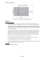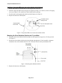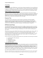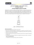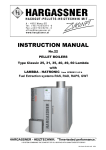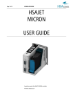
1
Temperature/RH Smart Sensor
The Temperature/RH smart sensor is designed
to work with HOBO® Station loggers and the
HOBO LCD logger with external probe input.
All sensor parameters are stored inside the
smart sensor, which automatically
communicates configuration information to the
logger without any programming, calibration or extensive user setup.
Inside this Package
•
Temp/RH Smart Sensor
Specifications
Temperature
RH
Measurement Range
-40°C to 75°C (-40°F to 167°F)
Accuracy
± 0.7°C at 25°C (1.3°F at 77°F), see
Figure 1 for detail
0.4°C at 25°C (0.7°F at 77°F), see
Figure 1 for detail
< 0.1°C (0.2°F) per year (typical)
0 to 100% RH between 0° and 50°C
(32°F and 122°F)
± 3%; ± 4% in condensing
environments
0.5% RH at 25°C (77°F)
Resolution
Drift
Calibration
Response Time
Operating Temperature Range
Environmental Rating
Housing
Dimensions
Weight
Bits per Sample
Number of Data Channels *
Measurement Averaging Option
Cable Lengths Available
Length of Smart Sensor Network
Cable *
Part Numbers
Specification
*
± 1% RH per year (typical); an
additional reversible drift up to +3%
can occur when the average relative
humidity is above 70% (see text
below)
Factory recalibration available
5 minutes, typical to 90% in 2 m/s
(4.5 mph) airflow
N/A
8 minutes, typical to 90% in 2 m/s
(4.5 mph) airflow
-40°C to +75°C (-40°F to +167°F)
Weatherproof: 0 to 100% RH Intermittent Condensing Environments up to
30°C, and non-condensing above 30°C. The Temp/RH Smart Sensor should
be mounted so that water does not impact or collect in the RH sensor.
Stainless steel
1.6 cm x 8.6 cm (5/8 in x 3.5 in)
2 meter: 60 g (2 oz), 6 meter: 140 g (5 oz), 17 meter: 370 g (13 oz)
8
2
No
2 meter – S-THA-M002 (6.5 ft), 6 meter – S-THA-M006 (19.7 ft),
17 meter – S-THA-M017 (55.7 ft)
2 meter – S-THA-M002 (6.5 ft), 6 meter – S-THA-M006 (19.7 ft),
17 meter – S-THA-M017 (55.7 ft)
S-THA-M002 (2 meter cable), S-THA-M006 (6 meter cable), S-THA-M017 (17
meter cable)
This product meets CE specification EN61326 criterion C for ESD, criterion C for
Radiated Immunity, criterion B for Fast Transient, criterion A for Conducted Immunity,
and criterion A for Power Frequency Magnetic Fields. To minimize measurement errors
due to ambient RF, use the shortest possible probe cable length and keep the probe
cable as far as possible from other cables.
A single HOBO Station can accommodate 15 data channels and up to 100 m (325 ft) of smart sensor cable (the digital
communications portion of the sensor cables).
© 2008 Onset Computer Corporation
Onset Part #: MAN-S-THA
Doc #: 5969-E
Temperature/RH Smart Sensor
Figure 1: Temperature Accuracy and Resolution
Mounting
Mounting Considerations
•
A solar radiation shield is strongly recommended when measuring air temperature in direct
sunlight. Solar radiation can be a significant source of error in the temperature and RH readings.
•
When mounting the probe, care should be taken to thermally isolate the sensor from the mounting
surface to ensure accurate air temperature and humidity readings. The probe’s temperature sensor
is inside the solid section of the stainless steel housing. For best results the entire probe should be
in the air being measured.
•
It is recommended that the probe be mounted horizontally or hanging downward from its cable.
This will reduce the possibility of moisture and condensation accumulating in the sensor housing.
Note: Mount the probe to ensure that the RH sensor is protected from direct splashing, rain, or
other sources of water saturation. If the probe is saturated, it will read approximately 110% RH
until it dries out. To dry the probe, shake the excess water off and/or move it to a dry location.
•
Dust on the sensor may adversely affect the RH sensor’s performance.
•
If you are running sensor cables along the ground, it is recommended that you use conduit to
protect against animals, lawn mowers, exposure to chemicals, and so on.
•
Refer to the HOBO Station Tri-pod Setup Guide for more information.
•
Refer to the HOBO LCD Data Logger User’s Manual for additional information about mounting
the temperature/RH sensor with the LCD logger.
Accessories
Solar Radiation Shield (part # M-RSA)
Page 2 of 6
Temperature/RH Smart Sensor
Installing a Temperature/RH sensor into a solar radiation shield (Optional)
1. Remove the bottom two shield plates by removing the three wing nuts.
2. Install the temperature/RH sensor using the two black loop clamps, two washers, and two self-tapping
screws (see Figure 2). Be careful not to block the RH sensor openings.
3. Feed the cable out through the third and fourth shield plates (see Figure 3).
4. Replace the bottom two shield plates.
Threaded rod (selftapping screw)
Temperature/RH
Temp/RH sensor
sensor cable
Loop clamp
Figure 2: Temperature/RH sensor inside solar radiation shield
Mounting the Solar Radiation Shield to the Tri-pod Mast
1. Mount the white solar radiation shield assembly onto the upper mast using the two U-bolts provided
(see Figure 3).
2. Position the solar radiation shield to the desired height and tighten the U-bolt assemblies. Optimum
orientation of the solar radiation shield is to face it into the direction of the predominant wind.
Figure 3: Mounting Solar Radiation Shield
3. Replace the bottom two shield plates.
Page 3 of 6
Temperature/RH Smart Sensor
Connecting
HOBO Station
To use the sensor with a HOBO Station, stop the logger and insert the modular jack into an available port.
If a port is not available, use a 1-to-2 adapter (Onset Part # S-ADAPT). The next time the HOBO Station
is launched, it will automatically detect the new sensor. Note that a HOBO Station supports a maximum
of 15 data channels. Use BoxCar Pro to launch the logger and verify the sensor is functioning correctly.
HOBO LCD logger with external probe input
To use the sensor with a HOBO LCD logger, insert the sensor into the jack on the side of the logger.
Note: You can only use one external sensor at a time with the LCD logger. Use BoxCar Pro to launch the
logger and verify the sensor is functioning correctly. The sensor must be connected to the logger when
logging begins; do not remove the probe once logging starts. See the HOBO LCD Data Logger User’s
Manual for more details about connecting the sensor to the logger.
Response Time
The sensors have 90% response times of 8 and 5 minutes for temperature and relative humidity
respectively. Faster sensor response times are not always better because they are more likely to be
affected by transient conditions. Ideally the response time of a sensor should be the same order of
magnitude as the logging interval. This smart sensor does not support measurement averaging. Sensor
values will not be affected if measurement averaging is selected during launch configuration.
RH Measurement Range
The temperature/RH sensor is designed to report relative humidity at temperatures between 0° and 50°C
(32°F and 122°F). Although the sensor will continue to report RH values throughout the entire operating
range of -40°C to 75°C (-40°F to 167°F), the values may not be accurate below 0° or above 50°C. The
sensor can be used in briefly condensing environments up to 30°C (86°F) and non-condensing above
30°C (86°F).
When using the sensor with the HOBO Weather Station, the relative humidity values will stay within -3%
to 103% (0 to 100% RH plus sensor error of ± 3%) under normal operating conditions. In certain
situations the RH may be reported outside of those normal limits. The lowest possible value is -5% and
the maximum value is 110% RH. When using the sensor with the HOBO LCD Temp/RH logger, the
relative humidity will stay within 0 to 100%.
See the sections below for detailed information about sensor performance in the following environments:
•
•
•
•
•
Condensation/Direct Water Exposure
High Humidity
Contamination from Salt
Contamination from Dust
Chemical Resistance
Condensation/Direct Water Exposure
When the RH sensor is covered in condensation, it will normally report between 100 and 104% RH with
the HOBO Weather Station and 100% with the HOBO LCD Temp/RH logger. If the RH sensor becomes
saturated (typically the result of immersion, puddling, rain, direct water spray, flooding, or extreme
condensation), the sensor will read full-scale 110% RH with the HOBO Weather Station and 100% with
the HOBO LCD Temp/RH. A saturated RH sensor will take a significant amount of time to dry out. Dryout time will vary with temperature, relative humidity, airflow, and sensor orientation. It is not unusual
for a sensor to take several hours to even a day or more to dry out.
Short-term condensation/water exposure does not do any harm at or below 25°C (77°F). At 30°C (86°F)
and above, however, short-term condensation/water exposure will result in a permanent positive drift.
Page 4 of 6
Temperature/RH Smart Sensor
Recalibrating the sensor or drying the sensor out cannot eliminate the drift. The humidity sensor must be
replaced and the new smart sensor must be moved to a more suitable location.
The effects of condensation/water exposure vary with both the length of exposure (time), the number of
exposures (repetitions), and the severity (temperature). When the RH sensor is subjected to repeated or
continuous exposure to water, it is likely that the sensor terminals will corrode. Long-term corrosion
results in a reduction of capacitance of the sensor terminals, which in turn results in an apparent reduction
of RH. Eventually the terminals will completely fail and the sensor will report negative full-scale values.
For more information, see Contamination from Salt.
High Humidity
If the sensor is in an environment with continuous high humidity, it will result in a positive, reversible
drift up to a maximum of +3%. The rate of drift is determined by temperature. See the table below for the
available data on drift at various temperatures.
Conditions
Typical Drift after 48 hours
Typical Drift after 1000 hours
50°C (122°F) 95% RH
+0.5 to 1% RH
+3% RH
25°C (77°F) 95% RH
< +0.5% RH Estimated
+3% RH
0°C (32°F) 95% RH
< +0.5% RH Estimated
+3% RH
In a “typical” environment where the sensor is subjected to high and low RH on a cyclical basis (daily or
every few days) and normal to low temperatures (less than 30°C [86°F]), the RH sensor may not drift at
all. An approximate way to tell if a sensor is likely to drift is to determine the average RH. If the average
RH is above 70%, it is likely the sensor will drift. If the average RH is less than 70%, drift is unlikely.
The maximum drift from exposure to a continuous high RH environment regardless of temperature is
about +3%.
This form of drift is reversible. If the sensor is placed in a relatively dry environment (less than about
50% RH), the sensor will recover. Dry-out rates will vary with temperature and relative humidity (warmer
temperatures and dryer air result in faster dry-out rates).
Contamination from Salt
Salt will accelerate corrosion of the RH sensor contacts. Although the contacts are gold plated, they will
corrode given the right conditions. As the electrodes corrode, the capacitance of the sensor will decrease
(lower RH reported) until eventually the contacts completely fail. Sensors with badly corroded terminals
will report negative full-scale values (-5%) with the HOBO Weather Station and 0% with the HOBO
LCD Temp/RH logger. The presence of salt on the sensor may not be obvious initially. Because salt is
hygroscopic (it attracts water), the moisture level next to the sensor will increase. This will result in an
increased RH level next to the sensor even as the corroding sensor terminals and decreasing capacitance
are causing an overall lower RH level. Erratic RH levels are often the result of salt contamination.
If salt is present on the sensor, it indicates that the sensor has most likely gotten wet. Possible sources are
saltwater spray (near the ocean), road salt spray, and repeated exposure to slightly salty irrigation water.
Contamination from Dust
“Clean” dust should not affect the RH sensor other than to slow the time response. Unfortunately dust is
rarely “clean.” Typically it contains small amounts of salt or other substances that will corrode the sensor
terminals (see Contamination from Salt). Dust is also often hygroscopic (attracts water).
Chemical Resistance
The sensor will fail after a few hours if exposed to acetone or chlorine gas. In addition, exposure to
petroleum-based solvents will result in a significant, permanent drift. In general, it is best to avoid placing
the sensor in a location where it will be exposed to chemicals or chemical vapors, such as acetone,
ammonia, chlorine, gasoline, oven cleaner, and auto exhaust.
Page 5 of 6
Temperature/RH Smart Sensor
Maintenance
The Temperature/RH smart sensor is sensitive to dust, salts and other airborne contamination.
Periodically inspect the RH sensor. If contamination is present on the sensor, gently rinse it with cool
fresh water. Never wash the sensor with hot water, organic solvents, or detergents.
Verifying Sensor Accuracy
It is recommended that you check the accuracy of the Temperature/RH smart sensor annually. This sensor
cannot be user-calibrated. Onset uses precision components to obtain accurate measurements. If the smart
sensor is not providing accurate data, then it may be damaged or out of calibration. If you are unsure of
the smart sensor’s accuracy, you can send it back to Onset for testing and possibly re-calibration of the
RH sensor. Contact Onset or your dealer for a Return Merchandise Authorization (RMA) number.
------------------------------------------------------------------------------------------------------------------------------© 2001–2005 Onset Computer Corporation. All rights reserved.
Onset, HOBO, and BoxCar are trademarks of Onset Computer Corporation.
The CE Marking identifies this product as complying with all relevant directives in the European Union (EU).
Page 6 of 6