1
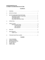
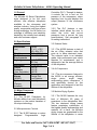
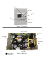
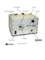
McIntire Model M300
Microwave Dehydrator
Operation Manual
745 Clark Ave. Bristol, CT 06010
800-4 DRY AIR (437-9247)
www.mcintirewireless.com
Thank you for choosing a McIntire Air Dryer System for your waveguide and cable
pressurization needs. All McIntire Dryer Systems have been designed to provide
years of outstanding performance and reliable service with minimal maintenance.
This manual covers the installation, operation, maintenance and servicing of the
Air Dryer System. Please read it carefully to better understand the dryer’s
operation and maintenance requirements.
About us…
Since 1963, McIntire Company has been engaged in the design, development,
manufacturing and field-service support activities of pressurization air dryer systems and
related accessory equipment.
The needs of the telecommunications industry have changed dramatically over the last
decade and we have continued to develop our product line to better serve the requirements
of this dynamic market. The acquisition of several, popular industry-related product lines
make “The McIntire Companies” the single largest and most complete supplier of
telecommunications pressurization equipment in the world. Our extensive catalog includes:
♦ Fully Automatic Air Dryer Systems with capacities from 200 SCFD to 30,000
SCFD engineered for maximum operational and servicing flexibility, minimum
maintenance and high reliability
♦ Central Office air distribution equipment including Manifolds, Racks, Cable
Transducer Panels, flow Transducer Pipe Panels, and all related fittings and
tubing from the Air Dryers to the cable vault.
♦ Manifolds, check valves, Air Feeder Pipe and associated fittings for use in
underground air distribution
♦ Manhole and work area protection equipment including ventilator/blowers,
portable heaters, hazardous gas monitors, manhole accessories and
complete traffic warning systems, all field proven and designed to provide
years of dependable service.
In addition, our nationwide repair facility in Somerset, New Jersey is equipped to handle
many types of repairs and maintenance including:
♦
♦
♦
♦
Piston-type Compressor Rebuilding and Repair
McIntire Water-seal Compressor Rebuilding and Repair
Complete Dryer Rebuilding
Western Progress Ventilator and Heater Repairs
For more information on any of the above products or services, call our Sales &
Service office toll free at 1-800-437-9247 or visit us on the web:
www.mcintireco.com
www.mcintirewireless.com
AUTOMATIC
AIR DEHYDRATION
SYSTEMS
MODEL M-300
INSTALLATION, OPERATING
AND MAINTENANCE MANUAL
DRYER SYSTEM LOG
Installation Data
Operating Manual Information
Manual 90547
Issue Date 1/06
Model No.________________
Serial No._________________
Compressor No. ___________
Installation Date____________
Location__________________
Bi-Annual Maintenance Kits:
Ordered
Installed
ADDENDA
Page No.
Revision
Date
4
Revised instructions to reflect Low Flow
Bypass Valve
11/22/06
4
Added Low Flow Bypass Valve drawing
11/28/06
7
Changed flow diagram to reflect Low Flow
Bypass Valve
11/28/06
8
Revised wiring diagram to reflect new
terminal block
12/01/06
10
Revised Figure 5 “Inside View” to reflect
PC board-mounted pressure transducer
11/28/06
11
Changed Figure 6 “Front View” to reflect
addition of Low Flow Bypass Valve
11/28/06
Added Section 8, “troubleshooting alarms”
11/28/06
5
McINTIRE COMPANY
SUBSIDIARY OF WM. STEINEN MFG. CO.
745 CLARK AVE., BRISTOL, CT 06010
1-800-437-9247
McINTIRE MODEL M-300
AUTOMATIC AIR DEHYDRATION SYSTEM
CONTENTS
1.
GENERAL...................................................................................................1
2.
SPECIFICATIONS......................................................................................1
3.
MAJOR COMPONENT DESCRIPTIONS...................................................1
MICROPROCESSOR CONTROLS.................................................1
SOLENOID VALVE..........................................................................1
AIR COMPRESSOR........................................................................1
MCINTIRE DRYING SYSTEM.........................................................1
4.
OPERATION...............................................................................................2
5.
INSTALLATION...........................................................................................3
MOUNTING OPTIONS.....................................................................3
FLOOR MOUNT....................................................................3
WALL MOUNT.......................................................................3
RACK MOUNT......................................................................3
6.
SERVICE....................................................................................................4
7.
MAINTENANCE..........................................................................................4
PARTS LIST.....................................................................................4
8.
TROUBLESHOOTING ALARMS…………………………………...…………5
FIGURES
1.
2.
3.
4.
5.
6.
FLOW DIAGRAM
WIRING DIAGRAM
MOUNTING OPTIONS
PLC INTERFACE
INSIDE VIEW
FRONT VIEW
McINTIRE MODEL M-300
AUTOMATIC AIR DEHYDRATION SYSTEM
McIntire M Series Dehydrators – M300 Operating Manual__________
1.0 General
The McIntire M Series Dehydrators
were designed to be the most
efficient, cost effective dehydrator
available to the microwave and
wireless industry. Using the highest
quality components and time proven
drying technology, the M Series is a
marriage of efficiency and simplicity
backed by the industry best warranty
and solid customer support.
Controller (PLC). Through its design,
it controls the cut in and cut out
pressure of the compressor, alarm
reporting, hour log and displays the
output pressure of the microwave
system.
3.2.2 The PLC features a user
interface which allows the user to
select the cut-in and cut-out
pressures from a pre-set list (see
specifications). See paragraph 5.9
for setting instructions.
2.0 Specifications
3.3 Solenoid Valve
Dimensions
(cm)
Weight
Electrical
Requirements
Capacity
LxWxH
17 x 11 x 10.5
(43 x 28 x 27)
45 lbs. (21 kg)
115 VAC/60 Hz
Up to.3 SCFM
(8.5 l/m)
0.1-90 Cu. Ft
Waveguide
2-4 PSI
Output
3-5 PSI
Pressure
(User Selectable) 4-8 PSI
Power
Standard
Excess Run
Alarms
(NO/NC)
Low Pressure
Optional Alarms Humidity
(Factory
Installed)
3.0 Major Component
Descriptions
3.1 The M-300 Dehydrator by
McIntire differs from most dehydrator
systems on the market because of
its unique technology.
3.2 Microprocessor Controls
3.2.1 The M 300 features a custom
designed
Programmable
Logic
3.3.1 The M-300 features a state of
the art 4-Way solenoid valve that
ports air to either desiccant tower.
The solenoid valve is an industrial
grade, high performance part which
requires no maintenance and is
designed to last the average lifetime
of the dehydrator.
3.4 Air Compressor
3.4.1 The air compressor featured in
the M-300 is an energy efficient,
single
piston,
single
stage,
reciprocating piston compressor. It
was specifically chosen for this
application and designed to last the
lifetime of the dehydrator.
3.5 McIntire Drying System
3.5.1 The M-300 features the very
best of McIntire’s 80 years of
experience in the dehydration field.
The two desiccant drying towers
feature proprietary construction of
the highest quality workmanship and
material. As a result, the McIntire
drying towers are guaranteed for the
lifetime of the dehydrator to never
________________________________________________________________________
For Sales and Service Call 1-800-4 DRY AIR (437-9247)
Page 1 of 6
McIntire M Series Dehydrators – M300 Operating Manual__________
need repacking or replacement. If it
is ever warranted, McIntire will
replace the towers free of charge.
controlled by precision flow orifices
that are part of the air director
assembly.
3.5.2 Continued life and regeneration
of the towers is achieved by the
patented McIntire Air Director,
described below in paragraphs 4.44.5.
4.5 When the air passes through the
orifice, it is relieved and expanded to
atmospheric pressure and free flows
through the offline tower to purge it
of moisture. This process is
dependant upon “system” pressure
inside the dehydrator that is greater
than what is present in the
microwave pressure system.
4.0 Operation
Refer to Figure 1
4.1 Air is drawn from the ambient
environment into the cylinder head of
the single piston compressor. The air
is then compressed by the force
applied by the piston and is
exhausted back through the cylinder
head exhaust port.
4.2 The air then migrates through a
pre-cooler which aids in dispersing
some of the heat generated by
compression.
4.2 The compressed air continues
through the 4-way solenoid valve
and, depending on its electrical
state, ports the air to one of two
desiccant drying towers.
4.3 The air travels through the tower
pre-determined
by
the
4-way
solenoid valve and because of the
desiccant material’s affinity for
moisture, the air is dried to less than
1% Relative Humidity (RH) or -40°C
atmospheric dew point.
4.4 Using the process known as
Pressure Swing Adsorption (PSA), a
small amount of dry air is diverted
through the opposite drying tower,
removing any moisture which may
be present. This “purge flow” is
4.6 The system pressure is regulated
by the check valve, which maintains
adequate pressure upstream to allow
PSA to take place, but regulates the
downstream pressure to prevent
over pressurization.
4.7 To further safeguard against over
pressurization, a safety relief valve is
installed in the air stream and will
open in the event the output
pressure should be above 10 PSI,
the typical maximum operating
pressure for microwave pressure
windows. This prevents any damage
from occurring in the event of a
malfunction.
4.8 The air then flows through the
moisture indicator window, and
depending on the position of the lowflow bypass valve, will purge a small
amount of air overboard. The
moisture indicator indicates the
effectiveness of the dehydrator
system. The indicator features a
color changing silica gel desiccant
which is dark blue in color when the
system is producing dry air, and
pinkish in color when the RH of the
output air has increased.
________________________________________________________________________
For Sales and Service Call 1-800-4 DRY AIR (437-9247)
Page 2 of 6
McIntire M Series Dehydrators – M300 Operating Manual__________
4.9 Air from the moisture indicator
window is also plumbed to the
pressure transducer, which in turn
generates an electronic pressure
reading and reports to the PLC. The
PLC interprets the pressure reading
and depending on the cut in and cut
out pressure setting turns the
compressor on or off. The PLC also
will report a low pressure alarm,
depending on the reading.
4.10 The air then flows to the air
outlet
where
the
microwave
pressurization system is ported
through a ¼” bulkhead fitting.
5.0 Installation
5.1 The M-300 was designed to be
easily mounted in a variety of
different ways.
5.1.1 The M-300 should be installed
in a suitable environment for
electronic equipment and within the
power cords length from a 115 VAC
power source. The unit draws
minimal amperage; a standard 15
amp circuit is more than suitable.
5.1.2 BEFORE continuing with the
installation, carefully inspect the unit
for signs of damage from shipping.
Immediately notify the responsible
carrier.
5.2 Locate the two (2) mounting
brackets that were shipped with the
unit.
5.3 Refer to Figure 2 for bracket and
mounting configurations.
5.4 Mounting Options
5.4.1 Floor Mount
5.4.1.1
The
M-300
features
rubberized feet which allow the unit
to be positioned directly on the floor
without concern for it “walking” with
vibration.
Note: Be aware of the possibility of
collected water, rodents, insects or
other undesirables in the location of
any floor mounted dehydrator.
5.4.2 Wall Mount
5.4.2.1 Figure 2 shows the bracket
configuration for wall mounting. For
convenience, the brackets can be
configured in two different ways to
accommodate wall mounting; one
which allows a direct mount to wall
studs (16” on center) and another
that allows for easy mounting to
plywood or other re-enforcement.
Note: It is strongly advised to NOT
wall mount directly to drywall or any
other thin building material. ½ or ¾”
plywood is preferred.
5.4.3 Rack Mount
5.4.3.1 The M-300 is designed to
also be rack mounted in either a 19”
or 23” rack. Refer to Figure 2 for
mounting bracket configurations to
accommodate the two different sized
racks.
5.5 Once the unit is installed, plug
the power cord into a suitable power
source (see paragraph 5.1.1).
5.6 Switch the power switch to the
“on” position, the compressor should
turn on immediately.
________________________________________________________________________
For Sales and Service Call 1-800-4 DRY AIR (437-9247)
Page 3 of 6
McIntire M Series Dehydrators – M300 Operating Manual__________
5.7 Allow the unit to run without
connecting it to the waveguide
pressurization system for 5-10
minutes. This should remove any
moisture that may have migrated into
the system during storage and/or
transport.
dryer will require more time to
pressurize the waveguide with this
valve open as the flow has been
reduced. This is normal. If your
installation does not cause the dryer
to short cycle, keep the valve closed
in the “OFF” position.
5.7 Inspect the moisture indicator
window for evidence of moisture
(pink desiccant). If moisture is
present, continue to run the unit.
Otherwise, if the desiccant is a dark
blue color, it is ready to be put online. Note: The blue indicating dye
in the moisture indicator reacts
slowly to changes in RH. Initial dryout time varies based on shelf time.
5.9 The factory settings for On and
Off pressures is 3 PSI (On) and 5
PSI (Off). To change this setting to
other preset options, press the “-”
and “+” Keys together, to scroll to
find the appropriate settings. Other
available options are 2 and 4 PSI
and 4 and 8 PSI.
5.8
Plumb
the
waveguide
pressurization system into the outlet
as acceptable by standard practices.
6.1 The M-300 requires little if any
service. Refurbishment services are
available through McIntire’s repair
services. Cal 1-800-4 DRY AIR (4379247) for details.
5.8.1 Note:
Some installations
incorporate a flow restrictive fitting
into the air inlet side of the
waveguide.
If your installation
utilizes such a fitting it may cause
the
dryer
to
“short-cycle”
accompanied by a measurable loss
ON
OFF
LOW FLOW
BYPASS
in pressure in the waveguide when
the compressor stops running. If you
experience the above symptoms,
open the Low Flow Bypass valve on
the top of the dryer by turning the
knob to “ON”. Please note that the
6.0 Service
6.2 Should emergency service or
maintenance be performed a list of
major parts is found below:
Part Number
M-2270-15
M-10129
11248
M-25427
M-25425
M-25426
M-22018
M-20144
M-21024
M-20723
M-11070
M-40488
Description
Cabinet Feet
Air Compressor
Compressor
Mount (x 4)
PLC
Dipole Relay
Unipole Relay
Alarm Lamp
Power Switch
4-Way Solenoid
Valve
Pressure
Transducer
Air Director
Humidity
Indicator
________________________________________________________________________
For Sales and Service Call 1-800-4 DRY AIR (437-9247)
Page 4 of 6
McIntire M Series Dehydrators – M300 Operating Manual__________
7.0 Maintenance
7.1 The McIntire M-300 dehydrator
was designed to require a minimal
amount of maintenance.
7.2 The only suggested maintenance
is the bi-annual replacement of the
air intake filter, PN M-11305. The
dehydrator accessory kit that came
with the original purchase contains 5
replacement filters; enough for
maintenance during the warranty
period.
7.3 To replace the filter, simply
remove the one that is in place by
turning it counter-clockwise.
7.4 Replace it with a new one by
screwing the new filter into the
bulkhead clockwise.
Note: Do NOT disassemble the filter
or attempt to replace the filter
element
alone.
Replace
the
complete assembly every time the
filter is to be replaced.
8.0 Troubleshooting Alarms
8.1 The M-300 should provide years
of trouble-free operation. Should an
alarm condition occur, refer to the
following section.
8.2 Excessive Run Alarm
8.2.1 The M-300 incorporates a
compressor overload alarm, also
known as excessive run. In the
event of an excessive run alarm, you
will get a visual indication from the
alarm light and a message on the
PLC display. This alarm will be
generated if the compressor runs
continuously for more than two hours
due to a leak in the dryer,
a
significant leak in the waveguide, or
a weak compressor.
8.2.2
In the event that the
compressor operates continuously
for more than two hours the external
alarm circuit will be activated and a
visual indication will occur while the
compressor continues to run. Once
the cause of the problem has been
detected
and
corrected,
the
excessive run alarm can be reset by
simply pushing the “B” and “-“ keys
together.
8.3 Low Pressure Alarm
8.3.1 The low output pressure alarm
condition is signaled via the PLC
which energizes the alarm relay.
The low pressure alarm is factory set
to occur when output pressure drops
below two PSI. The air dryer will
continue to run in the event of a low
pressure alarm.
8.3.2 If a low pressure alarm occurs
the following conditions may exist: A
significant increase in waveguide
demand caused by a leak in the
waveguide or a system leak within
the dryer. Other causes of a low
pressure alarm may indicate a weak
compressor or a faulty pressure
transducer. If the display on the PLC
reads
a
negative
pressure
accompanied by a low pressure
alarm, the transducer is defective or
the PLC is not receiving a signal
from the pressure transducer.
Check wiring from the transducer to
the PLC and tubing from the
transducer to the humidity indicator.
________________________________________________________________________
For Sales and Service Call 1-800-4 DRY AIR (437-9247)
Page 5 of 6
McIntire M Series Dehydrators – M300 Operating Manual__________
If wiring and tubing are correct and in
place, replace the transducer.
8.4 Power Failure Alarm
8.4.1 In the event of a power failure,
an external alarm signal is sent out
and all settings on the dryer will
default to the factory settings (3-5 psi
pressure setting) upon restoration of
power.
________________________________________________________________________
For Sales and Service Call 1-800-4 DRY AIR (437-9247)
Page 6 of 6
Air Director
Assembly
Check Valves
Pre-Cooler
Low Flow
Bypass
Humidity
Indicator
Air Compressor
Pressure Transducer
Figure 1 – M300 Pneumatic Flow Diagram
4-Way
Solenoid
Valve
Desiccant
Drying Towers
Safety Relief
Valve (10 PSI)
Compressor
Inlet filter
Ambient Air
Dry Compressed Air
Wet Compressed Air
Wet Purge Air
LEGEND
Air Outlet
Figure 2 - Dehydrator Wiring Diagram
Model M-300
23” Rack Mount
19” Rack Mount
Wall Mount
16” Stud Mount
Figure 3 - Mounting Options
“+” Key
“Esc” Key
“OK” Key
“A” Key
“-” Key
“B” Key
Figure 4 - PLC Interface
Pressure Transducer
Drying Tower B
Air Compressor
Air Director
Drying Tower A
Alarm Relays
Figure 5 - Inside View
Safety Relief Valve
Air Outlet
Low Flow Bypass
Alarm Connecting Block
Alarm Indicator
PLC Interface
Power (On/Off)
Figure 6—Front View
Inlet Filter
Humidity Indicator
Pink = Wet
Blue = Dry