1
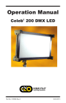
Operation Manual
VistaBeam® 600/300
VistaBeam 600 Center
VistaBeam 600 Pole-Op
Part No. 3100041 Rev D
01-04-2010
VistaBeam Fixture Styles and Features
VistaBeam Center Mount
VIS-6C-120
VistaBeam 600 DMX Center Mount, 120VAC
VIS-6C-230
VistaBeam 600 DMX Center Mount, 230VAC
VIS-3C-120
VistaBeam 300 DMX Center Mount, 120VAC
VIS-3C-230
VistaBeam 300 DMX Center Mount, 230VAC
VistaBeam Yoke Mount
VIS-6Y-120
VistaBeam 600 DMX Yoke Mount, 120VAC
VIS-6Y-230
VistaBeam 600 DMX Yoke Mount, 230VAC
VIS-3Y-120
VistaBeam 300 DMX Yoke Mount, 120VAC
VIS-3Y-230
VistaBeam 300 DMX Yoke Mount, 230VAC
2
VistaBeam Pole-Op Mount
VIS-6P-120
VistaBeam 600 DMX Pole-Op Mount, 120VAC
VIS-6P-230
VistaBeam 600 DMX Pole-Op Mount, 230VAC
VIS-3P-120
VistaBeam 300 DMX Pole-Op Mount, 120VAC
VIS-3P-230
VistaBeam 300 DMX Pole-Op Mount, 230VAC
Included w/ all VistaBeam Models
LVR-V690
VistaBeam 600
Louver–Honeycomb 90° (Included)
LVR-V390
VistaBeam 300
Louver-Honeycomb 90° (Included)
GFR-V6
VistaBeam 600 Gel Frame (Included)
GFR-V3
VistaBeam 300 Gel Frame (Included)
True Match® Lamps
964-K29
96W Kino KF29 (Twin)
964-K32
96W Kino KF32 (Twin)
964-K55
96W Kino KF55 (Twin)
3
VistaBeam 600 Center Mount Kits
KIT-V6C-120
VistaBeam 600 DMX Center Kit, 120VAC
KIT-V6C-230
VistaBeam 600 DMX Center Kit, 230VAC
Kit Contents:
1 VistaBeam 600 DMX Center Mount
1 VistaBeam Louver 90°
1 Ship Case
Dimensions
41.5 x 15.5 x 44"
(105.5 x 39.5 x 112cm)
Weight
140lb (63kg)
KIT-V6C-120/2
VistaBeam 600 DMX Center Mount Kit,
120VAC (2-Unit)
KIT-V6C-230/2
VistaBeam 600 DMX Center Mount Kit,
230VAC (2-Unit)
Kit Contents:
2 VistaBeam 600 DMX Center Mount
2 VistaBeam Louver 90°
1 Ship Case
Dimensions
41 x 27 x 44"
(102.5 x 67.5 x 112cm)
Weight
205lb (93kg)
4
VistaBeam 300 Center Mount Kits
KIT-V3C-120
VistaBeam 300 DMX Center Kit, 120VAC
KIT-V3C-230
VistaBeam 300 DMX Center Kit, 230VAC
Kit Contents:
1 VistaBeam 300 DMX Center Mount
1 VistaBeam Louver 90°
1 Ship Case
Dimensions
42 x 14.5 x 25.5"
(107 x 37 x 65cm)
Weight
82.3lb (37kg)
5
Inserting Lamps
1.
2.
3.
4.
1) Open the two hinged reflector panels. 2 & 3) Insert the lamp base into the
lamp connector. 4) Insert the lamp tip into the lamp clip. Close the reflector
panels.`
Inserting Gel Frame
Align the pins of the
Gel Frame with the inner
(closest to lamps) holes of
the Accessory Holder. Pull back
the pins and release into the
holes to secure the gel frame.
6
Applying Gel to Frame
(A)
(B)
A) The Gel Frame comes with Gel Clips. Cut the gel to size and use the
Clips to fasten the gel to the Frame.
B) Another method is to apply transfer tape directly to the gel frame.
The clips are not necessary when taping the gel.
Inserting Louver
Align the pins of the louver with the outer (farthest from lamps)
receptacle holes on the Accessory Holder. Pull back the pins and
release into the hole to secure the louver.
Mount Option / Rope Hang
The large holes on the Accessory
Holder can be used as rigging points;
for example, a 4 point rope hang.
7
VistaBeam Center Mount
The VistaBeam Center Mount includes a
Center Mount Assembly (MTP-V63C) and a
Junior Stand Adapter (MTP-V63JR) which can
be mounted onto a junior stand.
Center Mount Rotation and Tilt Controls
A) The gold lock lever controls the rotation of the fixture.
B) The black knob controls the tilt.
Center Mount Hanging Adapter
The VistaBeam Center Mount can also hang from a
junior pipe hanger using a Hanging Adapter
(MTP-V63H1), sold separately.
Remove the Junior Pin (MTP-V63JR) and attach
the Hanging Adapter. It is held in place by a safety
screw and a setscrew. A lock knob adjusts rotation
of the arm.
8
Center Mount Speed-Rail Rigging
The Mount fittings are U.S. industry
standard “Speed Rail” 1 ¼” fittings.
They accept a 1 5/8” outside
diameter pipe.
These fittings enable custom frames
to be constructed for special rigging
applications such as multiple fixture
hangs.
VistaBeam Yoke Mount
The yoke has a ½” hole to accept
industry standard hardware.
The VistaBeam 600 and 300 Yoke
Mount fixtures can hang from a junior
pipe hanger using a Yoke Junior Pin
(MTP-I80), sold separately.
MTP-I80 Yoke Junior Pin
9
VistaBeam Pole-Op Mount
The VistaBeam 600 and 300 Pole-Op
Mount fixtures include a yoke with an
attached junior pin.
They can be hung from a grid with a
junior pipe hanger.
Junior pin attached to Pole-Op Yoke
Operating Pole-Op
The Blue cup alters the Pan
(left or right).
The White cup alters the Tilt
(up or down).
10
VistaBeam DMX Control Panel
A
I
B
C
H
D
G
E
F
A) DMX-In & DMX-Out: DMX-IN receives DMX signals from Dimmer Board.
DMX-OUT relays DMX signal through to other Fixtures or Instruments.
B) Individual Lamp / Fixture Switch: Converts between INDIVIDUAL LAMP
and FIXTURE methods of DMX control.
C) DMX Address: Sets DMX Address of Fixture.
D) STD/HO Switch: STD operates lamp in standard output mode.
HO operates Lamps in High Output mode.
E) REMOTE Input Jack: Input for DIM-5 remote controller
11
F)
Power Switch: Has a built-in indicator light, which can detect if AC power
is present in power cord. "O" = OFF position
G) Manual SELECT Dial: Turns lamps on and off manually without connecting
DMX Cable to Fixture.
H) END of LINE Switch: Terminates DMX signal at the end of Fixture series.
I)
DMX Indicator Light: Lights up Amber when valid DMX signal is present.
IMPORTANT!
The dimmer board/light console should have its channel set to LINEAR light
output response. (LINEAR response is the default setting on most dimmer
boards.)
Power & Fuse Requirements
POWER
Provide 120VAC or 230VAC depending
on model. Do not dim the fixture through
a dimming circuit. If powering the fixtures
through a dimmer board, set the dimmer
profile to non-dim.
FUSE
Provides circuit protection. Note: If Fuse
is "blown" or "open" replace with same
type of fuse rating as marked.
Load Considerations:
The Kino Flo ballasts used in the VistaBeam are not power factor corrected.
They will draw double the current on the neutral from what is being drawn
on the two hot legs. On large installations it may be necessary to double
your neutral run so as not to exceed your cable capacity.
12
Manual Operation
The VistaBeam DMX fixture may be operated manually with the Manual
Lamp Selector Dial. The Dial enables you to turn lamps on and off with an
“inside-out” pattern (i.e., if all lamps are on, the outside tubes will turn off
first).
Note: Manual lamp switching is disabled as soon as DMX cables are applied.
VistaBeam 600 Switching
VistaBeam 300 Switching
STD operates lamps in Standard Output mode.
HO operates lamps in High Output mode.
Lamps can be controlled manually through a hand
held remote controller (DIM-5). For Manual Remote
Lamp Control plug in the accessory DIM-5. Rotating
the dimmer knob turns lamps on and off in sequence.
13
DMX Operation
DMX Addressing
Push the tabs above or below the
number window to set the address.
(Valid addresses range from 001
to 512.) The yellow light above the
address block will illuminate if a
DMX signal is present.
Tip: Power is not required to
set DMX addresses. Therefore,
DMX addresses can be set for
each fixture prior to hanging.
After the DMX address is entered, the VistaBeam 600 Fixture automatically
assigns 7 addresses to lamp positions 1–6 and address 7 controls the
STD/HO setting.
Note: Manual lamp switching is disabled as soon as the DMX cables are
applied. For Manual control with DMX cables plugged in, set address to “000”.
There is a 5 second delay when switching between DMX and Manual control.
NOTE: If a Fixture or Ballast loses its DMX signal it will hold its last DMX
command. For this reason it is important to turn a Fixture or Ballast off using
the DMX commands.
For example, if you try to turn off the lights by turning off the dimmer board
the lights will remember their last DMX command and stay on. The Fixtures
or Ballasts require a DMX “Off” or “Black-out” command in order to turn off.
The END of LINE switch must be set to open
( O ) on Fixtures within the DMX chain.
Set to closed (END of LINE) when the Fixture is
the last DMX controlled device in the chain.
Note: When the last Fixture's DMX Term is set
to “I”, it will absorb all energy in the DMX line,
ensuring DMX signals are transmitted correctly.
If a signal is not terminated, it is called a
“Reflected Wave”, and may create transmission
errors by causing valid DMX signals to be
canceled.
14
Any theatrical lighting board with DMX512 protocol
can be used to individually turn on/off lamps in a
Fixture.
VistaBeams can be jumpered using the IN and OUT
ports. As many as 100 Fixtures can be jumpered on
one chain as long as the DMX cable run remains
under 1000 feet or 40 x 25ft DMX cables.
Note: When operating Fixtures at great distances
from the dimmer board it is recommended to use
Opto-Isolators to provide DMX signal amplification.
DMX Cables
Cable must comply with EIA-485 (RS485).
The Fixture uses five-pin XLR male and female
connectors to receive DMX signals from the
Dimmer Board and jumper the Fixtures in a series.
DMX pin-out wiring follows the USITT DMX512
standard:
Pin 1: Shield
Pin 2: Data Pin 3: Data +
Pin 4: Spare Pin 5: Spare +
Note: Pin four and five in the Fixture are connected
internally as Pin four to four and Pin five to five.
Connecting Pin four and five as the pass-thru allows
secondary data to be passed through for other
equipment.
Fixture Mode
Setting the unit to "FIX” mode allows the user to
re-create the “Inside-Out" pattern of the manual
switch.
One of the best applications for the Fixture mode is
when lighting Blue and Green Screens or large
Cycloramas.
For example: One row of fixtures can be set to
Fixture mode on a common address. When the
fader on the dimmer board is brought up or down all
the Fixtures on that address will have the same
lamps turned on.
15
Addressing: In Fixture mode selecting the base address
automatically assigns the 7th address (in VistaBeam 600)
to control the STD/HO setting. For example, setting 001 as the
first address automatically assigns address 007 as the control
address for the STD/HO setting. Not assigning the 7th address
results in the fixture operating at the HO setting.
For the sake of simplification, it is advisable to select address
sequences such as 10, 20, 30, 40 and so on. This also allows
the operator to change from Fixture mode to Individual Lamp
mode without readdressing the fixtures. Never assign the
7th address to a new fixture. In the VistaBeam 300 every
4th address controls the STD/HO setting.
Dimmer level - Lamp response
Sliding the fader on the dimmer board from 0 ~ 100 controls
the number of lamps that are on within a fixture.
Note: the lamps may respond ± 4 channel levels, depending on
the dimmer board.
VistaBeam 600 Lamp
Sequence
DMX Address # 001
Lamp #
Dimmer
Level
Lamp 1
6
Lamp 1~2
19
Lamp 1~3
32
Lamp 1~4
45
Lamp 1~5
57
Lamp 1~6
95
DMX Address # 007
HO
STD
0
50
16
VistaBeam 300 Lamp
Sequence
DMX address # 001
Lamp #
Lamp 1
Dimmer
Level
6
Lamp 1~2
50
Lamp 1~3
DMX address # 004
HO
STD
95
0
50
The VistaBeam 600’s 7th DMX address
controls the STD/HO function.
The VistaBeam 300’s 4th DMX address
controls the STD/HO function.
Programming the STD/HO address
at full dimmer setting activates the
STD setting. Not using this address or
programming a dim setting under
50% will activate the HO setting.
Individual Lamp Mode
Setting the unit to Individual Lamp mode allows each lamp
position within the fixture Sequence to have its own address.
Although this option will use up a lot of addresses, it may be
preferable for certain situations. The Individual Lamp mode
is useful in achieving light effects like flickering, chasing or
creating light patterns.
After the DMX address is entered, the VistaBeam 600
automatically assigns 7 addresses to lamp positions 1-6
and the 7th address controls the STD/HO settings. For the sake
of simplification, it is advisable to select address sequences
in groups of 10 for VistaBeam 600 & VistaBeam 300 such as
10, 20, 30, 40 and so on.
17
For example, if the VistaBeam base address is set at 001,
the configurations below will provide lamps individually
addressable through DMX512.
VistaBeam 600
Address Sequence
VistaBeam 600 Lamp
Sequence
DMX Address = 001
Lamp #
Lamp 1
Lamp 2
Lamp 3
Lamp 4
Lamp 5
Lamp 6
STD/HO
DMX Address
1
2
3
4
5
6
7
VistaBeam 300
Address Sequence
VistaBeam 300 Lamp
Sequence
DMX Address = 001
Lamp #
Lamp 1
Lamp 2
Lamp 3
STD/HO
DMX Address
1
2
3
4
18
Accessories & Parts
DIM-5
Remote Lamp Selector
GFR-V6
VistaBeam 600 Gel Frame
GFR-V3
VistaBeam 300 Gel Frame
LVR-V345 VistaBeam 300 Louver 45°
LVR-V360 VistaBeam 300 Louver 60°
LVR-V390 VistaBeam 300 Louver 90°
LVR-V645 VistaBeam 600 Louver 45°
LVR-V660 VistaBeam 600 Louver 60°
LVR-V690 VistaBeam 600 Louver 90°
MTP-V63C
VistaBeam 63 Center Mount Assembly
19
MTP-V63H1
VistaBeam 63
Center Hanging Adapter (28mm)
MTP-V63JR
VistaBeam 63
Center Junior Adapter (28mm)
MTP-I80
Yoke Junior Pin (28mm)
XLR-515
DMX Cable 5 Pin XLR, 15ft
XLR-525
DMX Cable 5 Pin XLR, 25ft
True Match® Lamps
964-K29
96W Kino KF29 (Twin)
964-K32
96W Kino KF32 (Twin)
964-K55
96W Kino KF55 (Twin)
20
Cases
KAS-V61
Part
Number
Description
KAS-V62
Dimensions
KAS-V31
Weight
(Empty)
Holds
KAS-V61
VistaBeam 600 Center 41.5 x 15.5 x 44"
Ship Case
(105.5 x 39.5 x 112cm)
94 lb
(42.3 kg)
VistaBeam 600 (1)
Louver (2)
KAS-V62
VistaBeam 600 Center
41 x 27 x 44”
Ship Case (2)
(102.5 x 67.5 x 112cm)
122 lb
(55 kg)
VistaBeam 600 (2)
Louver (4)
KAS-V31
VistaBeam 300 Center
Ship Case
KAS-VL8
VistaBeam 8-Lamp
Ship Case
KAS-VL8-C VistaBeam 8-Lamp
Travel Case
42 x 14.5 x 25.5"
(107 x 37 x 65cm)
38 x 14 x 7"
(96.5 x 35.6 x 17.8cm)
37 x 7.5 x 14"
(94 x 19.1 x 35.6cm)
55 lb
VistaBeam 300 (1)
(24.8 kg) Louver (2)
13.4 lb
(6 kg)
13lb
(5.9kg)
VistaBeam Lamps
(8)
VistaBeam Lamps
(8)
21
Fixture Specifications
Model: VIS-6C
VistaBeam 600 DMX Center Mount
VistaBeam 600
Center Mount
Power Requirements: 120VAC or 230VAC
Amperage: 9.1 amps at 120VAC
4.6 amps at 230VAC
Weight w/ lamps: 46.6lb / 21kg
Dimensions: 37.5 x 36 x 8.5”
(95.5 x 91.5 x 21.5cm)
Remote Lamp Select: Phono jack input for
Remote Control
Switching:
1-6
Lamp type: 96W CFL
Model: VIS-3C
VistaBeam 300 DMX Center Mount
VistaBeam 300
Center Mount
Power Requirements: 120VAC or 230VAC
Amperage: 4.8 amps at 120VAC
2.4 amps at 230VAC
Weight w/ lamps: 28.6lb / 12.9kg
Dimensions: 37.5 x 20 x 8.5”
(95.5 x 51 x 21.5cm)
Remote Lamp Select: Phono jack input for
Remote Control
Switching: 1-3
Lamp type: 96W CFL
22
Model: VIS-6Y
VistaBeam 600 DMX Yoke Mount
VistaBeam 600
Yoke Mount
Power Requirements: 120VAC or 230VAC
Amperage: 9.1 amps at 120VAC
4.6 amps at 230VAC
Weight w/ lamps: 47.5lb / 21.4kg
Dimensions: 41.5 x 39.5 x 8.5”
(105.5 x 100.5 x 21.5cm)
Remote Lamp Select: Phono jack input for
Remote Control
Switching: 1-6
Lamp type: 96W CFL
Model: VIS-3Y
VistaBeam 300 DMX Yoke Mount
VistaBeam 300
Yoke Mount
Power Requirements: 120VAC or 230VAC
Amperage: 4.8 amps at 120VAC
2.4 amps at 230VAC
Weight w/ lamps: 28.6lb / 12.9kg
Dimensions: 41.5 x 24.5 x 8.5”
(105.5 x 62.2 x 21.5cm)
Remote Lamp Select: Phono jack input for
Remote Control
Switching: 1-3
Lamp type: 96W CFL
23
Model: VIS-6P
VistaBeam 600 DMX Pole-Op Mount
VistaBeam 600
Pole-Op Mount
Power Requirements: 120VAC or 230VAC
Amperage: 9.1 amps at 120VAC
4.6 amps at 230VAC
Weight w/ lamps: 47.5lb / 21.4kg
Dimensions: 41.5 x 39.5 x 8.5”
(105.5 x 100.5 x 21.5cm)
Remote Lamp Select: Phono jack input for
Remote Control
Switching: 1-6
Lamp type: 96W CFL
Model: VIS-3P
VistaBeam 300 DMX Pole-Op Mount
VistaBeam 300
Pole-Op Mount
Power Requirements: 120VAC or 230VAC
Amperage: 4.8 amps at 120VAC
2.4 amps at 230VAC
Weight w/ lamps: 29.5lb / 13.4kg
Dimensions: 41.5 x 24.5 x 8.5”
(105.5 x 62.2 x 21.5cm)
Remote Lamp Select: Phono jack input for
Remote Control
Switching: 1-3
Lamp type: 96W CFL
For latest Warranty information and Certifications,
see Kino Flo website at www.kinoflo.com.
Environmental: Disposal of Old Electrical & Electronic Equipment.
This symbol on the product or on its packaging indicates that this product
shall not be treated as household waste. This product is made of recyclable
materials and should be disposed of in accordance with local and state
regulations.
Kino Flo, Inc. 2840 N. Hollywood Way, Burbank, CA 91505, USA
Tel: 818 767-6528 website: www.kinoflo.com
24