1
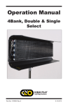
Operation Manual
Image 85/45
DMX
Image 85 Yoke Mount
Image 85 Pole-Op
Part No. 3100035 Rev C
01-04-2010
Image Fixture Styles and Features
Image Yoke Mount
IMG-85X-120
Image 85 DMX Yoke Mount, 120VAC
IMG-85X-230
Image 85 DMX Yoke Mount, 230VAC
IMG-45X-120
Image 45 DMX Yoke Mount, 120VAC
IMG-45X-230
Image 45 DMX Yoke Mount, 230VAC
Image Pole-Op Mount
IMG-85P-120
Image 85 DMX Pole-Op Mount, 120VAC
IMG-85P-230
Image 85 DMX Pole-Op Mount, 230VAC
IMG-45P-120
Image 45 DMX Pole-Op Mount, 120VAC
IMG-45P-230
Image 45 DMX Pole-Op Mount, 230VAC
2
Included w/ all Image Models
GFR-I80
Image 85 Gel Frame (Included)
GFR-I40
Image 45 Gel Frame (Included)
LVR-I80-S
Image 85 Silver Louver (Included)
LVR-I40-S
Image 45 Silver Louver (Included)
True Match® Lamps
488-K29-S
488-K32-S
488-K55-S
488-K10-S
488-K5-S
4ft Kino 800ma KF29
4ft Kino 800ma KF32
4ft Kino 800ma KF55
4ft Kino 800ma 420 Blue
4ft Kino 800ma 525 Green
Note: Kino Flo recommends
Safety-Coated 420nm Blue for Bluescreen
and 525nm Green for Greenscreen.
3
Image 85 Yoke Mount Kits
KIT-I85-X1/120
Image 85 DMX, Kit, 120VAC
KIT-I85-X1/230
Image 85 DMX Kit, 230VAC
Image 85 Yoke Kit
Kit Contents:
1 Image 85 DMX Yoke Mount
1 MTP-I80 Mount
1 Ship Case
Dimensions
56.5 x 8 x 35”
(143.5 x 20.5 x 89cm)
Weight
65 lb (29.3kg)
KIT-I85-X2/120
Image 85 DMX, Kit, 120VAC (2-Unit)
KIT-I85-X2/230
Image 85 DMX Kit, 230VAC (2-Unit)
Image 85 Yoke Kit (2)
Kit Contents:
2 Image 85 DMX Yoke Mount
2 MTP-I80 Mount
1 Ship Case
Dimensions
56.5 x 16 x 35”
(143.5 x 40.5 x 89cm)
Weight
167 lb (75.2kg)
4
KIT-I85-X4/120
Image 85 DMX, Kit, 120VAC (4-Unit)
KIT-I85-X4/230
Image 85 DMX Kit, 230VAC (4-Unit)
Image 85 Yoke Kit (4)
Kit Contents:
4 Image 85 DMX Yoke Mount
4 MTP-I80 Mount
1 Ship Case
Dimensions
35 x 33 x 64”
(89 x 84 x 162.5cm)
Weight
353 lb (160kg)
Image 45 Yoke Mount Kits
KIT-I45-X1/120
Image 45 DMX, Kit, 120VAC
KIT-I45-X1/230
Image 45 DMX Kit, 230VAC
Image 45 Yoke Kit
Kit Contents:
1 Image 45 DMX Yoke Mount
1 MTP-I80 Mount
1 Ship Case
Dimensions
56.5 x 9 x 23.5”
(143.5 x 23x 59.5cm)
Weight
48 lb (21.6kg)
5
Inserting Lamps
Insert lamps into both lamp holders. Twist ¼ turn to make
electrical contact.
Inserting Gel Frame
The gel frame is secured to the fixture by 4 spring-loaded pins.
Align the pins of the gel frame with the oval receptacle holes on
the edge of the fixture. Pull back the pins and release into the
receptacles to properly secure the gel frame.
Applying Gel to Frame
A) The Gel Frame comes with
Gel Clips. Cut the gel to size and
use the Clips to fasten the gel to
the Frame.
(A)
(B)
B) Another method is to apply
transfer tape directly to the gel
frame. The clips are not
necessary when taping the gel.
6
Inserting Louver
Place the long edge of the Louver into the lower channel containing a set
of leaf springs. Press down on the Louver and slip the upper edge of the
louver into the upper channel of the fixture. To remove reverse the procedure.
Mounting Barndoors
Side Door (x2)
Top and Bottom Door
1. For the Side Doors, align the hinge bracket tabs
with the two square receptacles on the side of the
fixture.
2. Press the tabs of both brackets into the square
receptacles.
3. Slide the two brackets up until the silver lock pin
snaps into place.
4. To release the Barndoor, press the lock pin down
and slide the bracket in reverse.
7
1. For the Top and Bottom
Doors, align the two hinge
bracket tabs with the two
square vents closest to the
silver lock pins.
2. Press the brackets down into
the vent and slide them over
to engage the lock pins with
the hole in the bracket.
3. To remove the Barndoor,
press down on the two lock
pins and slide the brackets
back.
Adjust the hinge tension with a
Phillips head screwdriver.
8
Image Yoke Mount
The Yoke has a ½” hole to accept industry standard
mounting hardware.
The Image 85 Yoke Mount can hang from a grid
by a junior pipe hanger using a Yoke Junior Pin
(MTP-I80), sold separately.
The Image 45 Yoke Mount can also hang from a
grid by a junior pipe hanger using a Yoke Junior Pin
(MTP-I80) or hang from a baby pipe hanger using a
Yoke Baby Receiver (MTP-I40) also sold separately.
The MTP-I80 includes a long bolt for the Image 85
Yoke Fixture and a short bolt for the Image 45 Yoke
Fixture.
Note: Because of weight capacity, the MTP-I40 can
only be used on the Image 45 Yoke Fixture.
Image Pole-Op Mount
The Image 85 and 45 Pole-Op Mount fixtures
include a yoke with an attached junior pin.
They can be hung from a grid with a junior pipe
hanger.
Junior pin attached to Pole-Op Yoke
9
Pole Operation
The Blue cup alters the Pan (left or right).
The White cup alters the Tilt (up or down).
Image Fixture DMX Control Panel
The Image 85 Fixture is used for example purposes throughout these
instructions.
A
B
C
D
E
F
G
H
I
J
A) Remote Jack: Input for remote hand-held lamp control. Turns lamps on and off
manually without connecting to DMX.
B) Manual Selector Dial: Turns lamps on and off manually without connecting
DMX Cable to Fixture.
C) HO/STD Selector Switch: HO setting operates all lamps in fixture at High Output.
STD setting operates all lamps in fixture at Standard light output. (STD is ½ f-stop
lower than HO.)
D) Power Switch: Has a built-in indicator light, which can detect if AC power is
present in power cord. "O" = OFF position.
E) Fuse: Provides circuit protection. Note: If Fuse is "blown" or "open" replace with
same type of fuse rating as marked.
F) DMX Address: Sets DMX Address of Fixture.
G) DMX Indicator Lamp: Lights if DMX is present and conforms to DMX512, 1990
H) Individual Lamp / Fixture Switch: Converts between INDIVIDUAL LAMP and
FIXTURE methods of DMX control.
10
I) DMX-In & DMX-Out: DMX-IN receives DMX signals from Dimmer Board.
DMX-OUT relays DMX signal through to other Fixtures or Instruments.
J) DMX TERMINATE Switch: Terminates DMX signal at the end of Fixture series.
IMPORTANT!
The dimmer board/light console should have its channel set to LINEAR light output
response. (LINEAR response is the default setting on most dimmer boards.)
Power Requirements
Provide 120 Volt AC primary power.
Do not dim the fixture through a dimming circuit.
If powering the fixtures through a dimmer board, set the dimmer profile to non-dim.
Load Considerations:
Kino Flo ballasts are not power factor corrected. They will draw double the current
on the neutral from what is being drawn on the two hot legs. On large installations
it may be necessary to double your neutral run so as not to exceed your cable
capacity.
Manual Operation
The REMOTE jack enables the use of a handheld remote controller
(Accessory Part # DIM-5, see page 17) to turn on lamps.
IMAGE 85 and 45 DMX Fixtures may be operated manually with the Manual
Lamp Selector Dial. The Dial enables you to turn lamps on and off with an
“inside-out” pattern (i.e., if all lamps are on, the outside tubes will turn off first).
The HO/STD switch sets the output level of all the lamps in the fixture. In HO mode
all lamps operate at a High Output level. In STD mode all lamps operate in Standard
light output. There is about a ½ f-stop drop in light in the STD mode.
11
DMX Image 85 Switching
DMX Image 45 Switching
Note: Manual lamp switching, HO/STD as well as remote hand-held control
(DIM-5) is disabled as soon as DMX cables are applied. For Manual control
with DMX cables plugged in, set address to “000”. There is a 5 second delay
when switching between DMX and Manual control.
DMX Operation
DMX Addressing
Prior to hanging any instruments set the
DMX address of each Fixture.
Push the tabs above or below the number
window to set the address.
(Valid addresses range from 001 to 512.)
The yellow light above the address block
will illuminate if a DMX signal is present.
12
Image 85 - Each Image 85 fixture operates on 9 addresses.
After the first DMX address is entered, the Image 85 Fixture automatically
captures 9 addresses to lamps 1 – 8 and the 9th address to control the
HO/STD Select feature. For the sake of simplification, it is advisable to
select address sequences such as 10, 20, 30, 40 and so on.
th
The 9 address controls the HO/STD setting of all the lamps in the fixture.
A dimmer level of 0%~50% sets the lamps in the HO mode. Dimmer settings
from 50%~100% sets the lamps into the STD mode.
Image 45 - Each Image 45 fixture operates on 5 addresses.
After the first DMX address is entered, the Image 45 Fixture automatically
captures 5 addresses to lamps 1 – 4 and the 5th address to control the
HO/STD Select feature. For the sake of simplification, it is advisable to
select address sequences such as 10, 15, 20, 25 and so on.
th
The 5 address controls the HO/STD setting of all the lamps in the fixture.
A dimmer level of 0%~50% sets the lamps in the HO mode. Dimmer settings
from 50%~100% sets the lamps into the STD mode.
Note: Manual lamp switching, remote hand control as well as HO/STD switching
are disabled as soon as the DMX cables are applied. For Manual control with
DMX cables plugged in, set address to “000”. There is a 5 second delay when
switching between DMX and Manual control.
IMPORTANT!
The dimmer board/light console should have its channel set to LINEAR
light output response. (LINEAR response is the default setting on most
dimmer boards.)
The DMX Terminate Switch must be set to open ( O )
on Fixtures within the DMX chain.
Set to closed ( I ) when the Fixture is the last DMX control
device in the chain.
Note: When the last Fixture's DMX Term is set to “I”, it will
absorb all energy in the DMX line, ensuring DMX signals
are transmitted correctly. If a signal is not terminated, it is
called a “Reflected Wave”, and may create transmission
errors by causing valid DMX signals to be canceled.
Any theatrical lighting board with DMX512 protocol can be
used to individually turn on/off lamps in a Fixture.
Image Fixtures can be jumpered using the IN and OUT
ports. As many as 100 Fixtures can be jumpered on one
chain as long as the DMX cable run remains under 1000
feet or 40 x 25ft DMX cables.
Note: When operating Fixtures at great distances
from the dimmer board, it is recommended to use
Opto-Isolators to provide DMX signal amplification.
13
DMX Cables
The Fixture uses five-pin XLR male and
female connectors to receive DMX signals
from the Dimmer Board and jumper the
Fixtures in a series. DMX pin-out wiring
follows the USITT DMX512 standard:
Do Not use Microphone Cables
and other general purpose,
two-core Cables designed for
audio or signaling use. They are not
suitable for DMX512. Problems due
to incorrect cabling may not be
immediately apparent. Microphone
Cables may appear to work fine,
but systems built with such Cables
may fail or be prone to random
errors. Cable must comply with
EIA-485 (RS485).
Pin 1: Shield
Pin 2: Data Pin 3: Data +
Pin 4: Spare Pin 5: Spare +
Note: Pin four and five in the Fixture are
connected internally as Pin four to four
and Pin five to five. Connecting Pin four
and five as the pass-thru allows secondary
data to be passed through for other
equipment.
NOTE: If a fixture or Ballast loses its DMX signal it will hold its last DMX
command. For this reason it is important to turn a Fixture or Ballast off using
the DMX commands. For example, if you try to turn off the lights by turning off
the dimmer board, the lights will remember their last DMX command and stay
on. The Fixture or Ballasts require a DMX “Off” or “Black-Out” command in
order to turn off.
Fixture Lamp Mode
Setting the unit to Fixture mode allows the
user to re-create the “Inside-Out" pattern of
the manual switch.
One dimmer channel controls the lamps,
a second channel the HO/STD setting.
Assign the first address to a dimmer
channel. Adjusting the slider up or down
sets the number of lamps to be turned on.
For HO/STD control on Image 85, assign
the 9th address to the second dimmer slider.
For Image 45, assign the 5th address to the
second dimmer. From 0%~50% operates all
the lamps in the fixture at HO mode, from
50%~100% in the STD mode.
14
One of the best applications for the Fixture mode is when lighting
Blue and Green Screens or large Cycloramas.
For example: One row of Image 85 fixtures can be set to Fixture
mode on a common address. When the fader on the dimmer board
is brought up or down, all the Fixtures on that address will have the
same lamps turned on. Assigning the 9th address on all the fixtures
renders control over the HO/STD settings.
Dimmer level - Lamp response
Sliding the fader on the dimmer board from 0% ~ 100% controls the
number of lamps that are on within a fixture. Note: the lamps may
respond ± 4 channel levels, depending on the dimmer board.
IMPORTANT!
The dimmer board/light console should have its channel set to LINEAR
light output response. (LINEAR response is the default setting on most
dimmer boards.)
Image 85 Lamp Sequence
DMX Lamp Sequence
Lamp # Dimmer Level
Lamp 1
6
Lamp 1~2
19
Lamp 1~3
32
Lamp 1~4
45
Lamp 1~5
57
Lamp 1~6
69
Lamp 1~7
82
Lamp 1~8
95
Image 45 Lamp Sequence
DMX Lamp Sequence
Lamp #
Dimmer Level
Lamp 1
12
Lamp 1~2
37
Lamp 1~3
64
Lamp 1~4
83
HO/STD Control: Image 85, assign a second dimmer channel to
the 9th address to control the HO/STD mode. Image 45, assign the
5th address. Dimmer level 0%~50% operates all the lamps in the
fixture at HO mode, from 50%~100% in the STD mode.
15
Individual Lamp Mode
Setting the unit to Individual Lamp mode allows each lamp within the fixture to
have its own address. Although this option will use up a lot of addresses, it may be
preferable for certain situations. The Individual Lamp mode is useful in achieving light
effects like flickering, chasing or creating light patterns.
After the first DMX address is entered, the DMX Image 85 automatically captures
th
9 addresses. Lamps are on addresses 1- 8. The 9 address controls the HO/STD
mode. For the sake of simplification, it is advisable to select address sequences such
th
as 10, 20, 30, 40 and so on. If the 9 address is not addressed the fixture will default
th
in the HO setting. Settings of 0%~50% on the dimmer slider on the 9 address will
operate lamps in the HO setting. Settings from 50%~100% operate the lamps in
the STD mode and the overall light output of the fixture drops by ½ f-stop.
For example, if the DMX Image 85 base address is set at 001, the configuration below
will provide eight lamps individually addressable through DMX512. Address 009 controls
the HO/STD mode.
Image 85 Lamp Sequence
Image 85 Address
Sequence
DMX Address = 001
Lamp #
Lamp 1
Lamp 2
Lamp 3
Lamp 4
Lamp 5
Lamp 6
Lamp 7
Lamp 8
HO/STD
Image 45 Lamp Sequence
DMX
Address
1
2
3
4
5
6
7
8
9
Image 45 Address
Sequence
DMX
Lamp #
Address
Lamp 1
1
Lamp 1~2
2
Lamp 1~3
3
Lamp 1~4
4
HO/STD
5
After the first DMX address is entered, the DMX Image 45 automatically captures
th
5 addresses. Lamps are on addresses 1– 4. The 5 address controls the HO/STD
mode. For the sake of simplification, it is advisable to select address sequences such
th
as 10, 15, 20, 25 and so on. If the 5 address is not addressed, the fixture will default
th
in the HO setting. Settings of 0%~50% on the dimmer slider on the 5 address will
operate lamps in the HO setting. Settings from 50%~ 100% operate the lamps in the
STD mode and the overall light output of the fixture drops by ½ f-stop.
16
Accessories
LVR-I80-B Image 85 Black Louver
MTP-I80
Yoke Junior Pin
MTP-I40
Yoke Baby Receiver
XLR-515 DMX Cable 5 Pin, 15ft
XLR-525 DMX Cable 5 Pin, 25ft
BRD-I80 Image 85 Barndoors, set of 4
BRD-I40 Image 45 Barndoors, set of 4
DIM-5
Remote Lamp Selector
17
True Match ® Lamps
488-K29-S
488-K32-S
488-K55-S
488-K10-S
488-K5-S
4ft Kino 800ma KF29
4ft Kino 800ma KF32
4ft Kino 800ma KF55
4ft Kino 800ma 420 Blue
4ft Kino 800ma 525 Green
Note: Kino Flo recommends
Safety-Coated 420nm Blue for Bluescreen
and 525nm Green for Greenscreen.
Cases
KAS-I80-1
Part
Number
KAS-I80-2
Description
Dimensions
KAS-I80-4
Weight
(Empty)
Holds
KAS-I40-1
Image 45 Ship Case (1)
56.5 x 9 x 23.5”
(143.5 x 23 x 59.5cm)
27lb / 12.2kg
Image 45 (1)
KAS-I80-1
Image 85 Ship Case (1)
56.5 x 8 x 35”
(143.5 x 20.5 x 89cm)
29lb / 13.1kg
Image 85 (1)
KAS-I80-2
Image 85 Ship Case (2)
56.5 x 16 x 35”
103lb / 46.4kg
(143.5 x 40.5 x 89cm)
Image 85 (2)
KAS-I80-4
Image 85 Ship Case (4)
33 x 35.5 x 64”
(84 x 90 x 162.5cm)
222lb / 100kg
Image 85 (4)
KAS-48
4ft Lamp Ship Case
52.5 x 10.5 x 11”
(133.5 x 26.5 x 28cm)
15.5lb / 7kg
INS-L4
4-Lamp Foam Pad
24 x 9 x 1”
(61 x 23 x 2.5cm)
N/A
4ft Lamps (20)
Fits KAS-48
18
Fixture Specifications
IMG-85X
Image 85 DMX Yoke
Image 85 Yoke
Power Requirements: 120VAC or 230VAC
Amperage: 8.6 amps at 120VAC,
4.3 amps at 230VAC
Weight w/ lamps: 38lb / 17.1kg
Dimensions: 54 x 28 x 6.5”
(137 x 71 x 16.5cm)
Lamp Select Switch: Rotary 1-8
Power Switch: On/Off (Lighted when On)
Remote Lamp Select: Phono jack input for
remote control
Lamp type: F75T12
IMG-45X
Image 45 DMX Yoke
Image 45 Yoke
Power requirements: 120VAC or 230VAC
Amperage: 4.5 amps at 120VAC,
2.3 amps at 230VAC
Weight w/ lamps: 25lb / 11.3kg
Dimensions: 54 x 17 x 6.5”
(137 x 43 x 16.5cm)
Lamp Select Switch: Rotary 1-4
Power Switch: On/Off (Lighted when On)
Remote Lamp Select: Phono jack input for
remote control
Lamp type: F75T12
19
IMG-85P
Image 85 DMX Pole-Op
Image 85 Pole-Op
Power Requirements: 120VAC or 230VAC
Amperage: 8.6 amps at 120VAC,
4.3 amps at 230VAC
Weight w/ lamps: 40lb / 18kg
Dimensions: 54.5 x 28 x 6.5”
(138.4 x 71 x 16.5cm)
Lamp Select Switch: Rotary 1-8
Power Switch: On/Off (Lighted when On)
Remote Lamp Select: Phono jack input for
remote control
Lamp type: F75T12
IMG-45P
Image 45 DMX Pole-Op
Image 45 Pole-Op
Power requirements: 120VAC or 230VAC
Amperage: 4.5 amps at 120VAC,
2.3 amps at 230VAC
Weight w/ lamps: 27lb / 12.2kg
Dimensions: 54.5 x 17 x 6.5”
(138.4 x 43 x 16.5cm)
Lamp Select Switch: Rotary 1-4
Power Switch: On/Off (Lighted when On)
Remote Lamp Select: Phono jack input for
remote control
Lamp type: F75T12
For latest Warranty information and Certifications,
see Kino Flo website at www.kinoflo.com.
Environmental: Disposal of Old Electrical & Electronic Equipment.
This symbol on the product or on its packaging indicates that this product
shall not be treated as household waste. This product is made of recyclable
materials and should be disposed of in accordance with local and state
regulations.
Kino Flo, Inc. 2840 N. Hollywood Way, Burbank, CA 91505, USA
Tel: 818 767-6528 website: www.kinoflo.com
20