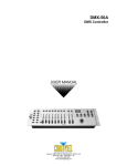
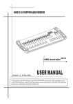
1
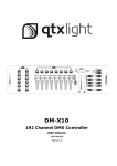
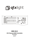
DM-X10 192 Channel DMX Controller Item ref: 154.091UK User Manual Version 2.0 Caution: Please read this manual carefully before operating Damage caused by misuse is not covered by the warranty Contents Getting started 1.1 What is included………………………………………………………………………………………………………………………………………. 3 1.2 Unpacking instructions……………………………………………………………..………………………………………………………………. 3 1.3 Safety instructions..........................................................…………..………………………………………………………………. 3 Introduction 2.1 2.2 2.3 2.4 Features..........................................................…………..……………………………………………………………….…………… General overview.............................................…………..……………………………………………………………….…………… Product overview.............................................…………..……………………………………………………………….…………… Common terms.............................................…………..……………………………………………………………….……………… 3 4 4 5 Operating instructions 3.1 Setup 3.1.1 Setting up the System.........................................................................…………………………………….……………… 3.1.2 Fixture Addressing............................................................................……………………………………….……………… 3.2 Operation 3.2.1 Manual Mode.................................................................................………………………………………….……..……… 3.2.2 Review Scene or Chase..........................................................................………………………………….……..……… 3.3 Programming 3.3.1 Entering program mode..................................................................………………………………………….……..……… 3.3.2 Create a scene.............. ...........................................................................…………..……………………………….… 3.3.3 Running a program........................................................................………………………………………….……..……… 3.3.4 Check Program..............................................................................………………………………………….……..……… 3.3.5 Editing a Program..........................................................................………………………………………….……..……… 3.3.6 Copy a Program.............................................................................………………………………………….……..……… 3.4 Chase Programming 3.4.1 Create a chase...............................................................................………………………………………….……..……… 3.4.2 Running a Chase............................................................................………………………………………….……..……… 3.4.3 Checking a Chase...........................................................................………………………………………….……..……… 3.4.4 Edit Chase (Copy Bank Into Chase)…........................................................................................................... 3.4.5 Edit Chase (Copy Scene Into Chase.................................................………………………………………….……..……… 3.4.6 Edit Chase (Insert Scene Into a Chase)..............................................……………………………………….……..……… 3.4.7 Delete a scene in a Chase...............................................................………………………………………….……..……… 3.4.8 Delete a Chase...............................................................................………………………………………….……..……… 3.4.9 Delete all Chase Programs..............................................................………………………………………….……..……… 3.5 Scene Programming (steps) 3.5.1 Insert a scene................................................................................………………………………………….……..……… 3.5.2 Copy a scene.................................................................................………………………………………….……..……… 3.5.3 Delete a scene...............................................................................………………………………………….……..……… 3.5.4 Delete all scenes........................................................................………………………………………….………...……… 3.6 Playback 3.6.1 Running in Sound-Mode............................................................………………………………………….………...……….. 3.6.2 Running in Auto-Mode.....................................................................……………………………………………………..… 3.6.3 Blackout................................................................................................................................................... 5 5 6 6 7 7 7 7 8 8 8 8 8 9 9 9 9 9 9 10 10 10 10 11 11 11 Appendix 4.1 4.2 4.3 4.4 2 DMX Primer………………………………………………………………………………………………………………………………………………. Fixture Linking............................................................................................................................................. DMX dipswitch quick reference chart............................................................................................................. Technical specifications ............................................................................................................................... 12 12 13 14 154.091UK User Manual Getting started 1.1 1.2 What is included DM-X10 controller DC 9-12V 500mA, 90V~240V Power Adapter Manual Unpacking Instructions Immediately upon receiving a fixture, carefully unpack the carton, check the contents to ensure that all parts are present, and have been received in good condition. Notify the shipper immediately and retain packing material for inspection if any parts appear damaged from shipping or the carton itself shows signs of mishandling. Save the carton and all packing materials. In the event that a unit must be returned to the factory, it is important that the unit be returned in the original factory box and packing. 1.3 Safety Instructions Caution: Please read this manual carefully before operating Damage caused by misuse is not covered by the warranty Please keep this User Guide for future consultation. If you sell the unit to another user, be sure that they also receive this instruction booklet. Always make sure that you are connecting to the proper voltage and that the line voltage you are connecting to is not higher than that stated on decal or rear panel of the fixture. This product is intended for indoor use only! To prevent risk of fire or shock, do not expose fixture to rain or moisture. Make sure there are no flammable materials close to the unit while operating. The unit must be installed in a location with adequate ventilation, at least 50cm from adjacent surfaces. Be sure that no ventilation slots are blocked. Always disconnect from power source before servicing or replacing lamp or fuse and be sure to replace with same lamp source. In the event of serious operating problem, stop using the unit immediately. Never try to repair the unit by yourself. Repairs carried out by unskilled people can lead to damage or malfunction. Please contact the nearest authorized technical assistance centre. Always use the same type spare parts. Don t connect the device to a dimmer pack. Make sure power cord is never crimped or damaged. Never disconnect power cord by pulling or tugging on the cord. Introduction 2.1 Features * * * * * * * 3 Universal DMX-512 Controller Controls 12 intelligent lights of up to 16 channels 30 banks of 8 scenes, 240 scenes total 6 sets of chases containing 240 scenes Execute multiple chases simultaneously Beat-activation, tap sync, auto run Polarity selector 154.091UK User Manual 2.2 General Overview The DM-X10 is a universal intelligent lighting controller. It allows the control of 12 fixtures composed of 16 channels each and up to 240 programmable scenes. Six chase banks can contain up to 240 steps composed of the saved scenes and in any order. Programs can be triggered by music, automatically or manually. All chases can be executed at the same time. On the surface you will find various programming tools such as 8 universal channel sliders and LED display indicators for easier navigation of controls and menu functions. 2.3 Product Overview (front) 1 2 3 4 5 6 7 8 Fixture Select Buttons Fixture Indicator LEDs Scene Select Buttons Channel Faders Page Select Button LCD Display Window Speed Fader Fade Time Fader 9 Bank Up Button 10 Bank Down Button 11 12 Program Button MIDI/Add Button 13 Auto/Del Button 14 Music/Bank Copy Button 15 Tap Sync Display Button 16 17 Chase Buttons Blackout Button 4 Select lighting fixture Indicate current fixtures Store and select scenes Adjust DMX parameter values Switch faders between 1-8 and 9-16 Displays current parameters or status Adjust scene hold time or step time Adjust the rate of fading / cross-fading Step forward scenes/steps in banks/chases Increment DMX values when FINE button is active Step backward scenes/steps in banks/chases Decrement DMX values when FINE button is active Enter Program mode Activate external control from MIDI / set MIDI address Activate Auto mode Delete key during Program mode Activate Music mode Copy key during Program mode Tap tempo sync during program playback Switch DMX display to percentage in Program mode Chase memory select 1-6 Switch all lights off 154.091UK User Manual 2.4 Common Terms The following are common terms used in intelligent light programming. Blackout is a state by where all lighting fixtures light output are set to 0 or off, usually on a temporary basis. DMX-512 is an industry standard digital communication protocol used in entertainment lighting equipment. For more information read Sections DMX Primer and DMX Control Mode in the Appendix. Fixture refers to your lighting instrument or other device such as a fogger or dimmer of which you can control. Programs are a bunch of scenes stacked one after another. It can be programmed as either a single scene or multiple scenes in sequence. Scenes are static snapshots of current channel values Faders are slider adjustment controls for various parameters Chases can also be called programs. A chase consists of a bunch of scenes stacked one after another. Scanner refers to a lighting instrument with a pan and tilt mirror; however, in the controller it can be used to control any DMX-512 compatible device as a generic fixture. Stand Alone refers to a fixture s ability to function independently of an external controller and usually in sync to music, from a built in microphone. Shutter is a mechanical device in the lighting fixture that allows you to block the lights path. It is often used to lessen the intensity of the light output and to strobe. Operating instructions 3.1 Setup 3.1.1 Setting up the system Plug the AC to DC power supply to the system back panel and to the mains outlet. Plug in your DMX cable(s) to your intelligent lighting as described in the fixtures’ user manuals. For a quick Primer on DMX see the “DMX Primer” section in the Appendix of this manual. 3.1.2 Fixture addressing The DM-X10 is programmed to control 16 channels of DMX per fixture, therefore the fixtures you wish to control with the corresponding FIXTURE buttons on the unit, must be spaced 16 channels apart. Fixture Default DMX Start Address 1 2 3 4 5 6 7 8 9 10 11 12 1 17 33 49 65 81 97 113 129 145 161 177 Binary DIP Switches Set to "ON" 1 1, 5 1, 6 1, 5, 6 1, 7 1, 5, 7 1, 6, 7 1, 5, 6, 7 1, 8 1, 5, 8 1, 6, 8 1, 5, 6, 8 Please refer to your individual fixture s manual for DMX addressing instructions. The table above refers to a standard 9 dipswitch binary configurable device. 5 154.091UK User Manual 3.2 Operation 3.2.1 Manual Mode The manual mode allows direct control of all fixtures. You are able to move them and change attributes by using the channel faders. Action 1. Select a FIXTURE button 2. Press the AUTO DEL button repeatedly until the MANUAL LED is lit. 3. Move the faders to change parameters for the selected fixture(s) PAGE/SELECT A/B button: Use to switch between fader control pages (A: Ch1~8), (B: Ch 9~16) TAP DISPLAY button: Press to toggle the output indicator on the LCD display between DMX values (0-255) and percentage (0-100) Note: All changes made within MANUAL mode will be temporary and will not be recorded 3.2.1 Review Scene or Chase This instruction assumes that you have already recorded scenes and chases on the controller. Otherwise skip this section and go to programming. Action 1. 2. 3. (SCENE review) Select a SCENE button (1-8) to review Select any one of the 30 banks by pressing the BANK UP/DOWN buttons Move faders to change fixture attributes Action 1. 2. 3. (CHASE review) Select a CHASE button (1-6) to review Press the TAP DISPLAY button to view the step number on the display Press the BANK UP/DOWN buttons to review all scenes in the chase Note: Make sure you are still in MANUAL mode 6 154.091UK User Manual 3.3 Programming A program (bank) is a sequence of different scenes (or steps) that will be called up one after another. In the DM-X10, 30 programs can be created with 8 scenes in each. 3.3.1 Entering Program Mode Press the Program button until the LED blinks. 3.3.2 Create a Scene A scene is a static lighting state. Scenes are stored in banks. There are 30 bank memories on the controller and each bank can hold 8 scene memories. The DM-X10 can save 240 scenes total. Action 1. Press and hold the PROGRAM button until the LED blinks. 2. Position SPEED and FADE TIME sliders all the way down. 3. Select FIXTURE(S) to begin adjusting the DMX values 4. Move faders to adjust parameters to the required setting for the fixture(s) 5. De-select a fixture to hold its DMX values 6. Adjust for all fixtures until all are set at the required state 7. Press the MIDI/ADD button 8. Select a BANK and then select a SCENE to store the scene 9. Press PROGRAM to store 10. Repeat the above process for up to 8 scenes in the bank 11. Hold the PROGRAM button to exit Program mode Notes: Deselect BLACKOUT if LED is lit. Toggle the PAGE SELECT button to access channels 9-16 All LEDs flash to confirm storing a scene Shortcut: Press [PROGRAM] [FIXTURES ] Adjust [Faders] [BANK] [SCENE] Press [PROGRAM] to store. 3.3.3 Running a Program Action: 1. Use BANK UP/DOWN buttons to change Program banks if necessary 2. Press the AUTO DEL button repeatedly until the AUTO LED turns on 3. Adjust the program speed via the SPEED fader and the loop rate via the FADE TIME fader. 4. Alternatively you can tap the TAP DISPLAY button twice. The time between two taps sets the time between SCENES (up to 10 minutes) Note: Deselect Blackout if LED is lit. 3.3.4 Check Program Action: 1. Press and hold the PROGRAM button until the LED blinks 2. Use BANK UP/DOWN buttons to change Program bank to review 3. Press the SCENES buttons to review each scene individually 7 154.091UK User Manual 3.3.5 Editing a Program Scenes will need to be modified manually Action: 1. Press and hold the PROGRAM button until the LED blinks 2. Use BANK UP/DOWN buttons to change Program banks if necessary 3. Select the desired fixture via the FIXTURES button 4. Move faders to adjust parameters to the required setting for the fixture(s) 5. Press the MIDI/ADD button to prepare the save 6. Select a SCENE to store the scene 3.3.6 Copy a Program Action: 1. Press and hold the PROGRAM button until the LED blinks 2. Use BANK UP/DOWN buttons to change Program bank to be copied 3. Press the MIDI/ADD button to prepare the copy 4. Use BANK UP/DOWN buttons to change the destination Program bank 5. Press the MUSIC BANK COPY button to copy to the new destination. All LEDs will blink to confirm 3.4 Chase Programming A chase is created by using previously created scenes. Scenes become steps in a chase and can be arranged in any order you choose. It is highly recommended that prior to programming chases for the first time; you delete all chases from memory. See Delete All Chases for instructions. 3.4.1 Create a Chase A Chase can contain 240 scenes as steps. The term steps and scenes are used interchangeably. Action: 1. Press and hold the PROGRAM button until the LED blinks 2. Press the CHASE (1-6) button you wish to program 3. Change BANK if necessary to locate a scene 4. Select a SCENE to insert 5. Press the MIDI/ADD button to store 6. Repeat steps 3 ~ 5 to add additional steps in the chase. Up to 240 steps can be recorded. 7. Hold the PROGRAM button to save the chase 3.4.2 Running a Chase Action: Press a CHASE button then press the AUTO DEL button. Adjust the Chase speed by tapping the TAP DISPLAY button twice at a rate of your choosing Note: The time between 2 taps will set the chase speed (up to 10 minutes) 3.4.3 Checking a Chase Action: 1. Press and hold the PROGRAM button until the LED blinks 2. Select the desired CHASE button 3. Press the TAP/DISPLAY button to switch the display to step view 4. Use BANK UP/DOWN buttons to review each scene in the chase 8 154.091UK User Manual 3.4.4 Edit Chase (Copy Bank into Chase) Action: 1. Press and hold the PROGRAM button until the LED blinks 2. Select the desired CHASE button 3. Select the Bank to be copied using the BANK UP/DOWN buttons 4. Press MUSIC/BANK COPY button to prepare the copy 5. Press MIDI/ADD button to copy. All LEDs will blink to confirm 3.4.5 Edit Chase (Copy Scene into Chase) Action: 1. Press and hold the PROGRAM button until the LED blinks 2. Select the desired CHASE button 3. Select the Bank that contains the Scene to be copied using the BANK UP/DOWN buttons 4. Select the SCENE to be copied 5. Press MIDI/ADD button to copy. All LEDs will blink to confirm 3.4.6 Edit Chase (Insert Scene into Chase) Action: 1. Press and hold the PROGRAM button until the LED blinks 2. Select the desired CHASE button 3. Press the TAP/DISPLAY button to switch the display to step view 4. Use BANK UP/DOWN buttons to navigate each scene in the chase until the insert point is reached 5. Press MIDI/ADD button to prepare the insert 6. Use BANK UP/DOWN buttons to navigate to the scene to be inserted 7. Press MIDI/ADD button to insert. All LEDs will blink to confirm 3.4.7 Delete a Scene from a Chase Action: 1. Press and hold the PROGRAM button until the LED blinks 2. Select the desired CHASE button 3. Press the TAP/DISPLAY button to switch the display to step view 4. Use BANK UP/DOWN buttons to navigate to the Scene to be deleted 5. Press AUTO/DEL button to delete. All LEDs will blink to confirm 3.4.8 Delete a Chase Action: 1. Press and hold the PROGRAM button until the LED blinks 2. Select the desired CHASE button 3. Press and hold the AUTO/DEL button and the CHASE button to delete. All LEDs will blink to confirm 3.4.9 Delete all Chase Programs Action: 1. Turn the DM-X10 power OFF 2. Press and hold the BANK DOWN and AUTO/DEL buttons together and switch the power back on 3. All LEDs will blink to confirm Chases have been deleted 9 154.091UK User Manual 3.5 Scene Programming (Steps) 3.5.1 Insert a Scene Action: 1. Press and hold the PROGRAM button until the LED blinks 2. Select the desired CHASE button 3. Press the TAP/DISPLAY button to switch the display to step view 4. Use BANK UP/DOWN buttons to navigate to the point at which to insert a Scene 5. Press the MIDI/ADD button to prepare to insert a scene 6. Use BANK UP/DOWN buttons to navigate to the scene that is to be inserted 7. Press the SCENE button that corresponds to the scene to be copied 8. Press the MIDI/ADD button to insert the scene. All LEDs will blink to confirm Note: To insert a scene between Steps 05 and 06 navigate using BANK buttons until the LCD reads STEP05. 3.5.2 Copy a Scene Action: 1. Press and hold the PROGRAM button until the LED blinks 2. Use BANK UP/DOWN buttons to navigate to the bank containing the Scene to be copied 3. Press the SCENE button that corresponds to the scene to be copied 4. Press the MIDI/ADD button to copy the scene 5. Use BANK UP/DOWN buttons to navigate to the bank that the Scene is to be copied into 6. Press the SCENE button where the Scene is to be copied into. All LEDs will blink to confirm 3.5.3 Delete a Scene Action: 1. Press and hold the PROGRAM button until the LED blinks 2. Use BANK UP/DOWN buttons to navigate to the bank containing the Scene to be deleted 3. Press and hold the AUTO/DEL button 4. Press the SCENE button that corresponds to the scene to be deleted. All LEDs will blink to confirm Note: When deleting a scene the physical location is not removed, however, all 192 DMX channels available to the scene will be set to value 0. 3.5.4 Delete All Scenes Action: 1. Press and hold the PROGRAM and BANK DOWN buttons whilst switching the power off 2. Turn the DM-X10 back on and all Scenes will be deleted Caution: This process is irreversible. All scenes with data will be set to 0. 10 154.091UK User Manual 3.6 Playback 3.6.1 Running in Sound mode Action: 1. Press and hold the MUSIC BANK COPY button until the MUSIC LED is lit 2. Use BANK UP/DOWN buttons to navigate to the bank which is to be run in Sound mode 3. Alternatively, you can press a single CHASE button or several CHASE buttons in sequence and all Chases will be run in the order selected 4. You can adjust duration time using the FADE TIME fader Note: In Sound mode, programs will be triggered by the sound using its built-in microphone. Multiple chases selected will loop and run in the order originally selected. 3.6.2 Running in Auto mode Action: 1. Press and hold the AUTO/DEL button until the AUTO LED is lit 2. If a CHASE button is not pressed, the DM-X10 will automatically run a BANK program 3. Use BANK UP/DOWN buttons to navigate to the bank which is to be run in Auto mode 4. Alternatively, you can press a single CHASE button or several CHASE buttons in sequence and all Chases will be run in the order selected 5. You can adjust time between steps using the SPEED fader and duration of the step using the FADE TIME fader 3.6.3 Blackout Action: 1. Press the BLACKOUT button to set all DMX values temporarily to 0 11 154.091UK User Manual APPENDIX 4.1 DMX Primer There are 512 channels in a DMX-512 connection. Channels may be assigned in any manner. A fixture capable of receiving DMX 512 will require one or a number of sequential channels. The user must assign a starting address on the fixture that indicates the first channel reserved in the controller. There are many different types of DMX controllable fixtures and they all may vary in the total number of channels required. Choosing a start address should be planned in advance. Channels should never overlap. If they do, this will result in erratic operation of the fixtures whose starting address is set incorrectly. You can however, control multiple fixtures of the same type using the same starting address as long as the intended result is that of unison movement or operation. In other words, the fixtures will be slaved together and all respond exactly the same. DMX fixtures are designed to receive data through a serial Daisy Chain. A Daisy Chain connection is where the DATA OUT of one fixture connects to the DATA IN of the next fixture. The order in which the fixtures are connected is not important and has no effect on how a controller communicates to each fixture. Use an order that provides for the easiest and most direct cabling. Connect fixtures using shielded two conductor twisted pair cable with three pin XLR male to female connectors. The shield connection is pin 1, while pin 2 is Data Negative (S-) and pin 3 is Data positive (S+). 4.2 Fixture Linking Caution: At the last fixture, the DMX-cable has to be terminated with a terminator. Solder a 120Ω resistor between Signal (-) and Signal (+) into a 3-pin XLR-plug and plug it in the DMX-output of the last fixture. In the Controller mode, at the last fixture in the chain, the DMX output has to be connected with a DMX terminator. This prevents electrical noise from corrupting the DMX control signals. The DMX terminator is simply an XLR connector with a 120W (ohm) resistor connected across pins 2 and 3, which is then plugged into the output socket on the last projector in the chain.The connections are illustrated below. 12 154.091UK User Manual 4.3 DMX DIP Switch Quick Reference Chart 13 154.091UK User Manual 4.4 Technical Specifications Power supply Max Operating Temperature DMX output MIDI input Data Pinout Protocol Dimensions Weight 9-12Vdc, 500mA (adaptor included) 45°C 3-pin XLRF 180° 5-pin DIN Pin 1 (GND), Pin 2 (-), Pin 3 (+) DMX512 USITT 482 x 130 x 70mm 3.5kg Disposal: The “Crossed Wheelie Bin” symbol on the product means that the product is classed as Electrical or Electronic equipment and should not be disposed with other household or commercial waste at the end of its useful life. The goods must be disposed of according to your local council guidelines. Errors and omissions excepted. Copyright© 2014. AVSL Group Ltd. 14 154.091UK User Manual