1
SERIAL
COMMUNICATION
INTERFACE
FOR
INDUSTRIAL
AUTOMATION
ADAM-4541
Fiber Optic to RS-232/422/485 Converter
Introduction
Specifications
* Casing: ABS with captive mounting hardware
Fiber optic transmission offers the benefits of wide
bandwidth, immunity to EMI/RFI interference, and
secure data transmission. The ADAM-4541 can be
used as an RS-232/422/485 point-to-point or
point-to-multipoint connection for transmitting and
converting full/half-duplex signals and their
equivalents within a fiber optic environment. Fiber
optics are the perfect solution for applications where
the transmission medium must be protected from
electrical exposure, lightning, atmospheric conditions
or chemical corrosion.
* Communication mode: Asynchronous
The ADAM-4541 is specifically designed to link
various machinery equipped with RS-232/422/485
communication ports (such as computer systems or
manufacturing machines) across distances in excess
of 2.5 km. Using standard ST connectors, the
module's fiber optic ports can accommodate a wide
range of fiber optic cable sizes, including 62.5/125 mm.
* Transmission mode: Full/Half-duplex, bidirectional
Features
* Compact size economizes space
* Direct plug-and-play
* Easily mounted on a DIN-rail, panel or piggyback
* Fiber optics: Multimode
* Connector: Plug-in screw terminal
* Fiber port: ST
* Transmission distance: Over 2.5 km
* Wavelength: 820 nm
* Optical power budget (attenuation): 12.5 dB
(measured with 62.5/125 mm optical fiber)
* Transmission rate: Up to 115.2 kbps
* Accessories (included): Nylon DIN-rail mounting
adapter, SECC panel mounting bracket
* Operating temperature: -10 ~ 70° C
(14 ~ 158° F)
* Operating humidity: 5 ~ 95% (non-condensing)
* Power consumption: 1 W (typical); 1.5 W (max)
Note:
* Transmission speeds of up to 115.2 kbps
Multi-mode fiber optics are designed for
industrial applications.
50/125 mm, 62.5/125 mm, and 100/140 mm
are commonly used.
* Multi-mode optical fibers enable transmission
farther than 2.5 km
Installation
* Half/Full-duplex, bidirectional transmission mode
* Avoids lightning strikes and EMI/RFI interference
* Prevents damage from electrostatic discharge
* Stable and error-free data transmission
* Automatic internal RS-485 bus supervision
* No external flow control signals required for
RS-485
* Transient suppression and over-current protection
on RS-422/485 data lines
* Reserved space for termination resistors
* Power and data flow indicators for
troubleshooting
* Power requirement: +10 ~ +30 VDC
ADAM and the ADAM logo are trademarks of Advantech.
Initial
Inspection
We carefully inspect the ADAM-4541 both
mechanically and electrically before we ship it. It
should be free of marks and scratches and in perfect
condition on receipt.
As you unpack the module, check it for signs of
shipping damage (damaged box, scratches, dents,
and so on). If it is damaged or fails to meet our
specifications, notify our service department or your
local sales representative immediately. Also, call the
carrier immediately and retain the shipping carton and
packing material for inspection by the carrier. We will
then make arrangements to repair or replace the unit.
Part No. 2000454100 1st Edition Printed in Taiwan April 1998
Before you begin installation, please make sure you
have the following items:
• 1 ADAM-4541 module
• 1 mounting bracket
• 1 user's manual
• 1 3P to DB 9 cable
Default
Defaultsettings
Function
Baud rate
Data format
Switch and jumper settings
Switch
settings
Both modules are not addressable by the host
computer. The baud rate and data format must be set
using SW1 and SW2 located inside the module. The
default settings are:
settings
DIP switches in the ADAM-4541 converter modules set
the data format (number of bits) and baud rate for the
ADAM network. You can configure the other modules in
the network via software commands. Your program and
the PC's serial port should match the settings of the
converter and repeater modules.
Setting
9600 bps
10 bits
The following tables illustrate the switch settings for
the ADAM-4541:
ADAM-4541 data format settings (SW1)
Data Format
1
2
9 bits
SW1
*10 bits
Switch 1 controls the data format. Data can be 9, 10,
11 or 12 bits. The factory default is 10 bits: one start
bit, eight data bits, no parity bit and one stop bit.
11 bits
12 bits
When using the converter in combination with other
ADAM modules, do not change the default setting,
because ADAM modules have a fixed data format of
ten data bits. The option of changing to 9, 11 or 12 bits
is for use with other modules (other than ADAM
modules) that have different data formats. Should you
change the ADAM module's data format, be aware that
you will also have to change the data format settings
on all the other modules in the network.
SW2
Switch 2 sets the baud rate. The options range from
1200 bps to 115.2 kbps. The factory default is 9600
bps. Be aware that when you change the baud rate,
you also have to change the baud rate for all the
connected modules accordingly. If the RS-232/422
mode is ON, the baud rate does not need to be set.
ADAM-4541 baud rate settings (SW2)
Baud Rate 1 2 3 4 5
1200 bps
l ¡ ¡ ¡ ¡
2400 bps
¡ l ¡ ¡ ¡
4800 bps
¡ ¡ l ¡ ¡
6
7
8
9
¡
¡
¡
¡
¡
¡
¡
¡
¡
¡
¡
¡
*9600 bps
¡
¡
¡
l
¡
¡
¡
¡
¡
19.2 kbps
38.4 kbps
57.6 kbps
115.2 kbps
RS-232/422
¡
¡
¡
¡
l
¡
¡
¡
¡
¡
¡
¡
¡
¡
l
¡
¡
¡
¡
¡
¡
¡
¡
¡
l
¡
¡
¡
¡
¡
¡
¡
¡
¡
l
¡
¡
¡
¡
¡
¡
¡
¡
¡
l
l= On
* = Default
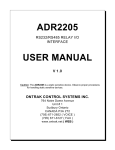
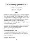
Diagram
Fiber
Optic
ADAM
4541
(Fiber
Repeating)
ADAM
4541
ADAM
4541
ADAM
4541
RS-485
Fiber
Optic
l= On
¡= Off
Block
RS-232
RS-422
¡= Off
¡
¡
l
¡
¡
l
l
l
* = Default
ADAM-5000/485
ADAM-4541
User's Manual
Example
Program
This program can be used as a diagnostic test for the ADAM-4541. It will transmit a string to COM1 and then
receive a string from COM1 (a loop-back test).
Program: LOOPBACK.C
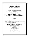
Signal Wiring
When you run the example program, you must
connect the ADAM-4541's terminals as follows:
#include <dos.h>
#include <io.h>
#include <stdio.h>
#include <conio.h>
PC
#define TIME OUT
4000
static int base0=0x3f8;
static int base1=0x2f8;
Rx
RS-232/422
static char rec[160];
ADAM-4541
static char cmd[160];
Tx
void main ()
{
int i,timeout;
char rflag,tflag;
bioscom(0,0xE3,0); /* Set COM1 as follows: Baud Rate = 9600, Data Bits = 8, */
printf("\nInput string : ");
/* Parity = none,
Stop Bits = 1 */
gets(cmd);
while (cmd[0] != 'q' && cmd[0] != 'Q')
{
cmd[strlen(cmd)] = 0x0d;
i=0;
tflag=1;
while (tflag)
{
/* Send data */
outportb (base0,cmd[i];
while ((inportb(base0+5) & 32) !=32);
rflag=1;
timeout=TIME_OUT;
while (rflag)
{
/* Check received data */
if ((inportb(base0+5) & 1) !=0)
{
/*Receive data */
rec[i]=inportb(base0);
if (rec[i] == 0x0d)
{
rec[i+1]='\0';
printf("\nReceived data : %s\n,rec);
tflag==0;
}
rflag=0;
}
else
{
/* Check timeout */
timeout--;
if (timeout == 0)
{
printf("Timeout error");
rec[i+1]='\0';
rflag=0;
tflag=0;
}
}
}
i++;
}
printf("\nInput command : ");
gets(cmd);
}
}
ADAM-4541
User's Manual
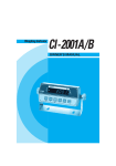
(R) +Vs
Possible reasons for malfunction
Ø The TX and RX connections are reversed.
Solution: Make sure the fiber connection is made
so that the TX of one end is connected
to the RX of the other.
(B) GND 10
Tr o u b l e s h o o t i n g
+
Ø Poor connection between the ADAM-4541 and the
communication port.
Solution: Make sure the ADAM-4541 is securely
plugged into the communication port.
Ø Attenuation on the fiber causes the signal level to
drop below the accepted level.
Solution: Reduce the attenuation by reducing
connector loss, transmission distances, etc.
Ø The connection between the communication ports
is neither DTE to DTE nor DCE to DCE, but is a
DTE to DCE connection.
Solution: Add a converter to one of the optical
modems, so that the pin assignments
from the communication port to the
modem are from pin 2 to pin 3 and from
pin 3 to pin 2.
- Power supply
+ +10 ~ +30 V
We advise that the following standard colors (as
indicated on the modules) be used for power lines:
+Vs
GND
è
è
(R) Red
(B) Black
Front View
Ø The fiber has been damaged.
Solution: Repair or replace the fiber.
Ø The ADAM-4541 has been damaged.
Solution: Use the supplied software to perform a
loop-back test of the optical modem to
determine whether it has really been
damaged.
Power Supply
For the ease of use in industrial environments, the
ADAM modules are designed to accept industry
standard +24 VDC unregulated power. Operation is
guaranteed when using any power supply between
+10 and +30 VDC. Power ripples must be limited to 5 V
peak to peak, while the voltage in all cases must be
maintained between +10 and +30 VDC. All power
supply specifications are referenced at the module
connector.
The power cables should be selected according to the
number of modules connected and the length of the
power lines. When using a network with long cables,
we advise the use of thicker wire, to limit line voltage
drop. In addition to serious voltage drops, long voltage
lines can also cause interference with communication
wires.
ADAM-4541
User's Manual