1
Introduction
The PCM-3640 is a PC/104-compatible 4-port RS-232
serial interface module. It works with PC/104 CPU modules
or CPU cards which accept PC/104 expansion modules. It
provides four independent serial interfaces, accessed
through male DB-9 connectors.
The module's industry-standard 16C550 asynchronous
communication chip is fully programmable. The module
requires no special commands or control codes if you use
the standard COM1 ~ COM4 port addresses.
Features
• Four RS-232 serial interfaces
• High speed data transmission—up to 115,200 Bps.
• Switch selectable addresses (COM1 ~ COM4 or any
other address from hex 200 to 3F8)
Initial inspection
We carefully inspected the PCM-3640 both
mechanically and electrically before we shipped it.
It should be free of marks and scratches and in
perfect electrical order on receipt.
Handle the board only by its edges. The static
charge on your body may damage its integrated
circuits. Keep the card in its anti-static package
whenever it is not installed. You can use this
package to return the card if it should need repair.
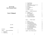
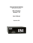
Switches and jumpers
The following chart shows the switches and
jumpers used to configure the PCM-3640:
• 16 bytes FIFOs
Switch Function
SW1
I/O base address (enhanced mode)
• Jumper selectable interrupt level
JP1
Channel 1 Interrupt level
• Eight LEDs indicate status of TX, RX lines (red LED
represents TX, green LED represents RX)
JP2
Channel 2 Interrupt level
JP3
Channel 3 Interrupt level
• Supported by PC-ComLib serial communication
programming library (optional)
JP4
Channel 4 Interrupt level
PCM-3640 PC/104 4-port RS-232
PCM-3640
PC/104 4-port RS-232 Module
Specifications
• Dimensions: 3.775" x 3.550" (9.6 cm x 9.0 cm)
Board Layout
• Bus: PC/104
• Baud rate: 50 to 115,200 bps
• Character length: 5, 6, 7 or 8 bits
• Parity: Even, odd or none
• Stop bit: 1, 1.5 (5-bit data only) or 2
• I/O connectors: Four male DB-9
• Interrupt level: IRQ 3, 4, 5, 6, 7 or 9
• Clock input: 1.8432 MHz
• Power consumption: +5 V @ 220 mA max.
PCM-3640 User's Manual
PC/104 and the PC/104 logo are trademarks of the PC/104 Consortium
Part no. 2000364000 1st Edition
1
Printed in Taiwan December 1994
Default jumper settings
The PCM-3640 will be shipped in standard mode, with the
following I/O address and IRQ settings:
Port
Port 1
I/O address
3F8
IRQ no.
IRQ4
Port 2
2F8
IRQ3
Port 3
3E8
IRQ12
Port 4
2E8
IRQ15
In enhanced mode, you can select a different base
address. The base address determines the address for
each of the four ports.
The I/O addresses for the four ports are as follows:
Port
I/O address
Port 1
Port 2
Base + 00H
Base + 08H
Port 3
Base + 10H
Port 4
Base + 18H
You use switches 1~6 of DIP switch SW1, a 7-position DIP
switch, to set the base address. You can set the base
address anywhere from hex 200 to 3F8.
Jumper and Switch settings
The PCM-3640 can be used in two modes: standard or
enhanced mode. In standard mode the I/O addresses are
compatible with the standard PC communication ports,
COM1 ~ COM4. In enhanced mode you can select a
different base address. The offset of each port from the
base address is fixed.
Standard / Enhanced mode selection
Switch 7 of DIP switch SW1 selects between standard and
enhanced mode.
Standard mode
SW1
In standard mode, the I/O address of the ports are as
follows:
Port
Port1
p.3)
I/O address
3F8
Interrupt No
Selectable (see
Port2
p.3)
2F8
Selectable (see
Port3
p.3)
3E8
Selectable (see
Port4
p.3)
2E8
Selectable (see
To set the base address, you have to calculate the base
address as follows:
NOTE: On the PCM-3640 the address line A9 does not
appear on the DIP switch as it is permanently hard-wired to
HEX 200 on the card.
The following table shows different base address settings.
Port base address (SW1)
Base address
A8
200-207
l
208-20F
¡
A3
A4
A5
A6
A7
l
l
l
l
l
l
l
l
l
l
¡
l
¡
¡
¡
l
¡
l
¡
¡
¡
¡
¡
¡
¡
¡
¡
¡
- 2E8-2EF
- -
Enhanced mode
3E8-3EF
- *3F8-3FF
l:ON
SW1
Note:
Base address selection(SW1)
2
¡:OFF
*:Default
If your CPU module or card has serial
interface ports, you will need to adjust
the I/O port addresses (or disable the
ports) to avoid conflicts.
PCM-3640 User's Manual
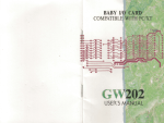
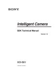
Interrupt level selection (JP1~ JP4)
You can set the interrupt level for each port from 3 to15,
except 8, 13 and 14. Jumpers JP1, JP2, JP3 and JP4 sets
the interrupt level for port 1, port 2, port 3 and port 4
respectively.
Simply short the pins on the jumper corresponding to the
interrupt level required (as illustrated below).
IRQ
IRQ
IRQ
IRQ
3
4
5
6
7
9 10 11 12 15
¡
¡
¡
¡
¡
¡
¡
¡
¡
¡
¡
¡
¡
¡
¡
¡
¡
¡
¡
¡
3
4
5
6
7
9 10 11 12 15
¡
¡
¡
¡
¡
¡
¡
¡
¡
¡
¡
¡
¡
¡
¡
¡
¡
¡
¡
¡
3
4
5
6
7
9 10 11 12 15
¡
¡
¡
¡
¡
¡
¡
¡
¡
¡
¡
¡
¡
¡
¡
¡
¡
¡
¡
¡
3
4
5
6
7
9 10 11 12 15
¡
¡
¡
¡
¡
¡
¡
¡
¡
¡
¡
¡
¡
¡
¡
¡
¡
¡
¡
¡
Note:
JP1
JP2
JP3
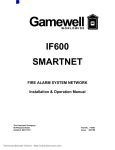
RS-232 Signal wiring
Since the RS-232 interface is not strictly defined, many
devices have their own connection methods which may
ignore some signal lines or define reserved lines to other
functions. It is best to refer to the user’s manual for your
device for installation instructions. You may find the
following helpful.
In general, DTE (Data Terminal Equipment) refers to the
device that is leading the communication. Examples
include PC’s, terminals and some printers. DCE refers to
the device being communicated with or controlled.
Examples include modems, DSU’s (digital service units),
printers and lab/factory equipment.
In some situations you may be able to get by with just
three lines: data on TxD, a Signal Ground and a
handshaking line. Examples are printer or plotter
connections, troubleshooting and situations where you
require only one-wire communication.
JP4
Do not use interrupts that are used by
other cards/ports, unless you have
made provision for interrupt sharing in
your programs.
Signal wiring
Connector pin assignments
Terminal or PC (DTE) connections
PCM-3640 (DTE): (DB-9)
Terminal (DTE):DB-25
Pin
3
Signal
TxD
Pin
3
Signal
RxD
2
RxD
2
TxD
7
RTS
5
CTS
8
CTS
4
RTS
6
DSR
20
DTR
5
GND
7
GND
4
DTR
6
DSR
1
DCD
8
DCD
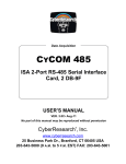
You access the PCM-3640's ports through four external
male DB-9 connectors. RS-232 connector pin assignments
are as follows :
Pin description
Modem connections
1
DCD receive line signal detector
1
2
RD
received data
2
3
TD
transmitted data
3
4
DTR data terminal ready
5
GND ground
Pin
3
Signal
TxD
6
DSR data set ready
2
RxD
3
TxD
7
RTS
7
RTS
4
CTS
RTS
6
7
8
4
9
5
request to send
PCm-3640: DB-9 Male
Modem (DCE)
Pin
2
Signal
RxD
8
CTS clear to send
8
CTS
5
9
RI
6
DSR
6
DTR
5
GND
7
GND
ring indicator
PCM-3640 User's Manual
3
4
DTR
20
DSR
Connecting to another PC/104 module
1
DCD
8
DCD
1. Insert the pins of connector JP6 (on the end of the
PCM-3640 module) into the piggyback connector on
the other PC/104 module.
For DTE to DCE connection, use straight through cable
connections, i.e. you don't have to reverse lines 2 and 3,
lines 4 and 5, and lines 6 and 20. Because in general DCE
RS-232 interfaces are reversed themselves.
Terminal without handshake
PCM-3640: DB-9 MALE
Pin
Signal
3
TxD
Pin
3
Terminal (DTE)
Signal
RxD
2
RxD
2
TxD
7
RTS
8
CTS
6
DSR
5
GND
7
GND
4
DTR
2. Screw the PCM-3640 to the brass spacer.
1
DCD
This completes the hardware installation.
The maximum length of a RS-232 cable is 100 ft. If you
need to connect over longer distances, (longer than 100 ft),
you will have to use another standard (like RS-422 or RS485).
If you do not use CTS, RTS, DSR, DTR signals, please
loop them back, otherwise the PC-ComLIB software will
not function correctly. PC-ComLIB always checks for
handshake signals.
Hardware installation
Warning!
TURN OFF your PC power supply
whenever you install or remove the
PCM-3640 or connect and disconnect
cables.
Installing the module on a CPU card
1. Turn the PC's power off. Turn the power off to any
peripheral devices such as printers and monitors.
2. Disconnect the power cord and any other cables from
the back of the computer.
3. Remove the system unit cover (see the user's guide for
your chassis if necessary).
4. Remove the CPU card from the chassis (if necessary)
to gain access to the card's PC/104 connector.
5. Screw the brass spacer (included with the module) into
the threaded hole on the CPU card. Do not tighten too
much, or the threads may be damaged.
6. Carefully align the pins of the PCM-3640 with the PC/
104 connector. Slide the module into the connector. The
module pins may not slide all the way into the
connector; do not push too hard or the module may be
damaged.
7. Secure the module to the CPU card to the threaded
hole in the CPU card using the included screw.
8. Attach any accessories to the PCM-3640.
9. Reinstall the CPU card and replace the system unit
cover. Reconnect the cables you removed in step 2.
Turn the power on.
4
(PCM-3640)
Programming
Programming with COM1 or COM2
If you set the PCM-3640's ports as COM1 and COM2, you
can send and receive data using the normal communication functions found in high-level languages. The following
examples use BASIC to demonstrate PCM-3640
programming.
The BASIC communication process starts with the OPEN
“COMn: , , ...” statement. This statement assigns a
buffer for communication purposes and sets up the
communication parameters.
Command format
OPEN “COMn: [speed][,parity][,data][,stop]
[,RS][,CS[n]][,DS[n]][,CD[n]][,LF][,PE]”
AS [#]filenum
Example:
OPEN “COM1:9600,N,8,,CS,DS,CD” AS #1
Where:
COMn:
n is 1 or 2, indicating either COM1 or COM2
speed:
An integer constant specifying the baud rate in
bits per second
parity:
One of
S:
O:
M:
E:
N:
data:
An integer constant indicating the number of
data bits. Valid values are 4, 5, 6, 7 and 8. The
default is 7.
stop:
The number of stop bits. Valid values are 1 and
2. The default is 2 for 75 and 110 bps, 1 for all
others.
RS:
Suppresses RTS
the following characters:
space
odd
mark
even
none
PCM-3640 User's Manual
CS:
Controls CTS
DS:
Controls DSR
CD:
Controls CD
LF:
Sends a line feed following each carriage return
PE:
Enables parity checking
filenum: filenum is an integer expression which evaluates
to a valid file number
You must put the speed, parity, data and stop parameters
in this position and order, but you can put the RS, CS, DS,
CD, LF and PE parameters in any order. The n argument in
the CS, DS and CD parameters specifies the number of
milliseconds to wait for the signal before returning a
“device timeout” error. n may range from 0 to 65535. If you
omit n or set it equal to 0, then the line status is not
checked at all.
Refer to the IBM BASIC reference manual for more
detailed information.
Programming example — standard COM ports
You can use the following BASIC program to test the PCM3640's send and receive functions.
10
‘**************************************************
20
‘* Program: DEMO01.BAS
*
30
‘* Description: This demo program transmits a
*
40
‘* string through COM1 and receives it through
*
50
‘* COM2
*
70
‘**************************************************
160 ‘Set the proper parameters
170 ‘COM1 & COM2: baud rate=9600 ; no parity check;
180 ‘Data bit=8; stop bit=1
190 ‘Ignore the CTS, RTS and DSR signals.
200 OPEN “COM1:9600,N,8,1,RS,CS,DS,CD” FOR RANDOM AS
#1
210 OPEN “COM2:9600,N,8,1,RS,CS,DS,CD” FOR RANDOM AS
#1
220 INPUT “INPUT COMMAND:”;CMD$
230 IF CMD$=”Q” OR “q” THEN CLOSE:END ELSE GOSUB 250
240 GOSUB 300:GOTO 220
250 ‘****** Transmit data sub-routine ******
260 PRINT #1,CMD$
270 RETURN
300 ‘****** Receive data sub-routine ******
310 T=TIMER:TEMP$=””:RX$=””
320 IF TIMER>T+.5 THEN PRINT “TIMEOUT ERROR”:RETURN
330 IF LOC(2)>0 THEN TEMP$=INPUT$(1,#2) ELSE GOTO 320
340 RX$=RX$+TEMP$
350 IF TEMP$=CHR$(13) THEN GOTO 360 ELSE GOTO 320
360 PRINT “RECEIVE DATA:”;RX$:RETURN
Using other I/O port addresses
If you are going to use I/O ports other than COM1 or
COM2, you will need to directly program the registers of
the PCM3640's 16C550 chip.
See page 7 for information on the format and programming
of these registers. See page 8 if you have trouble finding a
free I/O port base address.
You can use the following program as a base as you
develop your own driver. The program exchanges data (the
numbers 0 to 256) between two ports. It uses I/O port
addresses hex 2E8 and 3E8. Set JP4, JP5 and JP10 for
RS485 or RS-422 mode (described on page 2).
Programming example—arbitrary I/O ports
10
20
‘****************************************
‘Clear the screen
PCM-3640 User's Manual
30
CLS
40
‘Set the I/O port base addresses for
50
‘both cards
60
PORT1%=&H2E8
70
PORT2%=&H3E8
80
‘Read all registers once to
90
‘clear any random data
100 FOR I=PORT1% TO PORT1%+6
110 DUM=INP(I)
120 NEXT I
130 FOR I=PORT2% TO PORT2%+6
140 DUM=INP(I)
150 NEXT I
160 ‘Initialize the registers of
170 ‘port1. First, set DLAB = 1 so the
180 ‘desired baud rate can be programmed.
190 OUT PORT1%+3,&H80
200 ‘Write the value of divisor into
210 ‘registers: hex 180 = dec 384 = 300 BAUD
220 OUT PORT1%,&H80:OUT PORT1%+1,&H1
230 ‘Set word length = 8 bits, stop bits = 2,
240 ‘even parity, DLAB = 0.
250 OUT PORT1%+3,&H1F
260 ‘Do the same thing for port2.
270 OUT PORT2%+3,&H80
280 OUT PORT2%,&H80:OUT PORT2%+1,&H1
290 OUT PORT2%+3,&H1F
300 ‘Loop over data (0-255) and send it
310 ‘from port1 to port2
320 FOR BYTE=0 TO 255
330 ‘Wait until the transmitter buffer
340 ‘is empty.
350 IF (INP(PORT1%+5) AND 32)=0 GOTO 350
360 ‘Output the data through port1.
370 OUT PORT1%,BYTE
380 ‘See if the data is available by checking
390 ‘the Data Ready bit.
400 IF (INP(PORT2%+5) AND 1)=0 GOTO 400
410 J=INP(PORT2%)
420 ‘Print out the data byte received
430 PRINT “port “;HEX$(PORT2%)” = “;HEX$(J)
440 ‘If the value sent <> the received value then
error
450 IF J<>BYTE GOTO 620
460 NEXT BYTE
470 ‘Loop over data (0-255) and send it
480 ‘from port2 to port1.
490 FOR BYTE=0 TO 255
500 ‘See if the transmitter buffer is empty.
510 IF (INP(PORT2%+5) AND 32)=0 GOTO 510
520 OUT PORT2%,BYTE
530 ‘See if the data is available by
540 ‘checking the Data Ready bit.
550 IF (INP(PORT1%+5) AND 1)=0 GOTO 550
560 J=INP(PORT1%)
570 PRINT “port “;HEX$(PORT1%)” = “;HEX$(J)
580 IF J<>BYTE GOTO 620
590 NEXT BYTE
600 ‘If everything is OK, then stop.
610 END
620 PRINT “Data transmission error!”:BEEP:END
Programming example—communication
The following pair of example programs show how you can
set up communication between two computers. The first
program sends data then receives data. The second
program receives data then sends data. Run the first
program on one computer and the second on another.
Program for first computer
10
20
30
40
50
60
70
80
90
100
110
120
130
150
160
170
180
190
‘************ STEP 1:
‘Clear screen
CLS
‘Define variables A to
DEFINT A-Z
‘Set port base address
PORT = &H3F8
‘Set baud rate to 300
OUT PORT + 3, &H80
OUT PORT, &H80
OUT PORT, 1
OUT PORT + 3, &H1F
‘******** STEP 2: SEND
FOR I = 65 TO 90
‘
GOSUB 200
NEXT I
GOTO 260
INITIALIZATION *************
Z as integer
(must match hardware)
DATA ********
5
200
210
220
230
240
250
260
270
280
290
300
310
320
330
STATUS = INP(PORT + 5) AND &H20
IF STATUS = 0 THEN 200
OUT PORT, I
FOR J = 0 TO 1200: NEXT J
RETURN
‘****** STEP 3: RECEIVE DATA *****
FOR I = 65 TO 90: GOSUB 280: NEXT I
END
STATUS = INP(PORT + 5)
IF (STATUS AND &H1E) THEN 280
IF (STATUS AND &H1) = 0 THEN 280
D = INP(PORT)
PRINT “DATA= “; CHR$(D)
RETURN
char flag; /* Flag for end of output/input data */
int timeout; /* Timeout counter */
outport((base0+2), 0xc9);
outport((base1+2), 0xc9);
/* enable port 0 FIFO */
/* enable port 1 FIFO */
/* Set communication parameters for port 0 */
outp(base0+3, 0x80); /* Set DLAB=1 */
/* Set baud = 115200 */
outp(base0, 0x01);
outp(base1+1, 0);
/* Set data=8, stop=1, no parity */
outp(base0+3, 0x03);
/* Disable port 0 interrupt */
outp(base0+1, 0x00);
Program for second computer
10
‘********** STEP1: INITIALIZATION **********
20
‘Clear screen
30
CLS
40
‘Define variables A TO Z as integer
50
DEFINT A-Z
60
‘Set port base address (must match hardware)
70
PORT = &H2F8
80
‘Set baud rate to 300
90
OUT PORT + 3, &H80
100 OUT PORT, &H80
110 OUT PORT, 1
120 OUT PORT + 3, &H1F
130 ‘***** STEP 2: RECEIVE DATA FROM ANOTHER PC *****
140 FOR I = 65 TO 90: GOSUB 190: NEXT I
150 PRINT: PRINT: PRINT
160 PRINT”DATA RECEIVES END, THEN DATA SEND BEGINNING.”
170 PRINT: PRINT “PRESS ANY KEY...”
180 IF INKEY$ = “” THEN 180 ELSE 260
190 STATUS = INP(PORT + 5)
200 IF STATUS AND &H1E THEN GOTO 190
210 IF (STATUS AND &H1) = 0 THEN 190
220 d = INP(PORT)
230 PRINT “DATA= “; CHR$(d)
240 RETURN
250 ‘*************** STEP 3: SEND DATA ***************
260 FOR I = 65 TO 90
270 d = I
280 GOSUB 310
290 NEXT I
300 END
310 STATUS = INP(PORT + 5) AND &H20
320 IF STATUS = 0 THEN 310
330 OUT PORT, d
340 FOR J = 0 TO 1200: NEXT J
350 RETURN
C language test program
/* Set communication parameters for port 1 */
outp(base1+3, 0x80); /* Set DLAB=1 */
/* Set baud = 115200 */
outp(base1, 0x01);
outp(base1+1, 0);
/* Set data=8, stop=1, no parity */
outp(base1+3, 0x03);
/* Disable port 1 interrupt */
outp(base1+1, 0x00);
printf("\nEnter a string to be transmitted "
"(15 characters or less) or Q to quit:");
gets(cmd);
while (cmd[0] != 'q' && cmd[0] != 'Q')
{
i=0;
cmd[strlen(cmd)] = 0x0d;
flag=1;
while (flag)
{
outportb(base0, cmd[i]);
/* Send data */
if (cmd[i] == 0x0d)
flag=0;
i++;
}
i=0;
flag=1;
timeout=TIME_OUT;
while (flag)
{
/* Check if receiver data is ready */
if ((inportb(base1+5) & 1) !=0)
{
rec[i]=inportb(base1); /* Receive data */
if (rec[i] == 0x0d)
{
rec[i+1]=’\0';
You can use the following C program to test the PCM3640's send and receive functions.
/
*******************************************************/
/* Program: DEMO01.C
*/
/* Description: This demo program transmits a string
*/
/* to COM1 and receives a string from COM2
*/
/* Compiler: Turbo C 2.0
*/
/
*******************************************************/
#include
#include
#include
#include
#define
static
*/
static
*/
static
static
/
<dos.h>
<io.h>
<stdio.h>
<conio.h>
TIME_OUT
10000
int base0 = 0x3f8;
/* Base address of port 0
int base1 = 0x2f8;
/* Base address of port 1
char rec[16]; /* Buffer for received string */
char cmd[16]; /* Buffer for transmitted string
void main()
{
int i; /* Counter for character being sent/received
*/
6
PCM-3640 User's Manual
flag=0;
printf(“\nReceived data: %s\n”, rec);
}
i++;
}
else
{
/* Check timeout */
timeout--;
if (timeout == 0)
{
flag = 0;
printf(“\nTimeout error\n”);
}
}
}
printf("\nEnter a string to be transmitted "
"(15 characters or less) or Q to quit:");
gets(cmd);
}
115200
BASE+1
BASE+2
Interrupt Status Register (ISR) when
DLAB=0
bit 0
Enable received-data-available
interrupt
bit 1
Enable transmitter-holding-registerempty interrupt
bit 2
Enable receiver-line-status interrupt
bit 3
Enable modem-status interrupt
FIFO Control Register (FCR)
bit 0
}
Register structure and format
This section gives short description of each of the module's
registers. For more information please refer to the data
book for the STARTECH 16C550 UART chip.
1
Enable transmit and receive FIFOs
bit 1
Clear contents of receive FIFO
bit 2
Clear contents of transmit FIFO
bit 3
Change RXRDY and TXRDY from
mode 0 to mode 1.
bits 6-7 Set trigger level for receiver FIFO
interrupt.
All registers are one byte. Bit 0 is the least significant bit,
and bit 7 is the most significant bit. The address of each
register is specified as an offset from the port base
address (BASE), selected with DIP switch SW1.
Bit 7
0
Bit 6
0
0
1
04
DLAB is the "Divisor Latch Access Bit", bit 7 of BASE+3.
1
0
08
BASE+0
Receiver buffer register when DLAB=0 and
the operation is a read.
1
1
14
BASE+0
Transmitter holding register when DLAB=0
and the operation is a write.
BASE+0
Divisor latch bits 0 - 7 when DLAB=1.
BASE+1
Divisor latch bits 8 - 15 when DLAB=1.
BASE+3
The two bytes BASE+0 and BASE+1
together form a 16-bit number, the divisor,
which determines the baud rate. Set the
divisor as follows:
FIFO trigger level
01
Line Control Register (LCR)
bit 0
Word length select bit 0
bit 1
Word length select bit 1
Bit 1
0
Bit 0
0
Word length (bits)
5
0
1
6
1
0
7
1
1
8
Baud rate
50
Divisor
2304
75
1536
bit 3
Parity enable
110
1047
bit 4
Even parity select
133.5
857
bit 5
Stick parity
150
768
bit 6
Set break
300
384
bit 7
Divisor Latch Access Bit (DLAB)
600
192
1200
96
1800
64
2000
58
2400
48
3600
32
bit 0
Receiver data ready
4800
24
bit 1
Overrun error
7200
16
bit 2
Parity error
9600
12
bit 3
Framing error
19200
6
bit 4
Break interrupt
38400
3
bit 5
Transmitter holding register empty
56000
2
bit 6
Transmitter shift register empty
bit 7
At least one parity error, framing
error or break indication in the
PCM-3640 User's Manual
bit 2
BASE+4
BASE+5
Number of stop bits
Modem Control Register (MCR)
bit 0
DTR
bit 1
RTS
Line Status Register (LSR)
7
FIFO
PC/104 Bus signal assignments
BASE+6
Pin
0
J1/P1
Row A
--
J1/P1
Row B
--
1
IOCHCHK*0V
J2/P2
Row C
0V
J2/P2
Row D
0V
SBHE*
Modem Status Register (MSR)
bit 0
Delta CTS
bit 1
Delta DSR
MEMCS16*
bit 2
Trailing edge ring indicator
LA23
bit 3
Delta received line signal detect
bit 4
CTS
DSR
2
SD7
IOCS16*
RESETDRV
3
SD6
+5V
LA22
IRQ10
bit 5
4
SD5
IRQ9
LA21
IRQ11
bit 6
RI
5
SD4
-5V
LA20
IRQ12
bit 7
Received line signal detect
6
SD3
DRQ2
LA19
IRQ15
7
SD2
-12V
LA18
IRQ14
8
SD1
ENDXFR* LA17*
DACK0*
9
SD0
+12V
MEMR*
DRQ0*
10
IOCHRDY (KEY)2
MEMW*
DACK5*
11
AEN
SMEMW* SD8
DRQ5
12
SA19
SMEMR* SD9
DACK6*
13
SA18
IOW*
SD10
DRQ6
14
SA17
IOR*
SD11
DACK7*
15
SA16
DACK3*
SD12
DRQ7
I/O address (hex)Assignment
000-1FF
used by base system board
16
SA15
DRQ3
SD13
+5V
200
17
SA14
DACK1*
SD14
MASTER*
201
game control
18
SA13
DRQ1
SD15
0V
202-277
not used
19
0V
SA12
REFRESH*
(KEY) 2
278-27F
second printer port
280-2F7
not used
20
SA11
SYSCLK
--
--
2F8-2FF
COM2
21
SA10
IRQ7
--
--
300-377
not used
22
SA9
IRQ6
--
--
378-37F
printer port
23
SA8
IRQ5
--
--
380-3AF
not used
24
SA7
IRQ4
--
--
3B0-3BF
monochrome adapter and printer
25
SA6
IRQ3
--
--
3C0-3CF
not used
26
SA5
DACK2*
--
--
3D0-3DF
color and graphics adapters
BASE+7
Temporary data register
Standard PC I/O port assignments
The following chart shows the I/O addresses used by
standard PC peripheral devices.
not used
27
SA4
TC
--
--
3E0-3EF
not used
28
SA3
BALE
--
--
3F0-3F7
floppy diskette drive
29
SA2
+5V
--
--
3F8-3FF
COM1:
30
SA1
OSC
--
--
31
SA0
0V
--
--
32
0V
0V
--
--
8
PCM-3640 User's Manual
PCM-3640 User's Manual
9