1
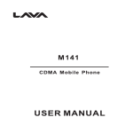
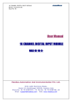
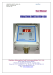
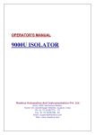
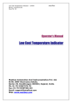
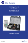
STATIC VOLTAGE STABILIZER – SINGLE PHASE
21.01.2012
USER MANUAL
STATIC VOLTAGE STABILIZER
True PWM controlled IGBT based Technology
(Single Phase Static Voltage Stabilizer (SVS))
THE GREEN POWER TO EMPOWER YOUR BUSINESS
SUVIK ELECTRONICS PVT. LTD.
Plot No. 102/A, GIDC Engineering Estate, Sector-28, Gandhinagar-3820028, (Gujarat), INDIA.Tel. +91-79-23212001, 23212002, and
23212003 Customer Support: +91-79-23212005. WWW.SUVIK.COM, [email protected]
SUVIK ELECTRONICS PVT LTD
VER. 1.1
PAGE 1 OF 13
STATIC VOLTAGE STABILIZER – SINGLE PHASE
21.01.2012
Revision details:
Sr No
1
2
Revison NO
1.0
1.1
Revison date
29/07/2011
21/01/2012
Remarks
Initial Draft
Final Release
SUVIK provides customers solutions with technical support. Users may contact the Customer service
department.
While every precaution has been taken to ensure accuracy and completeness in this manual, SUVIK assumes no
responsibility and disclaims all liability for damages resulting from use of this information or for any errors or
omissions.
SUVIK pursues a policy of continuous product development and reserves the right to change the equipment
design without notice. The contents in this document are subject to change without notice
SUVIK ELECTRONICS PVT LTD
VER. 1.1
PAGE 2 OF 13
STATIC VOLTAGE STABILIZER – SINGLE PHASE
21.01.2012
TABLE OF CONTENTS
1.0
IMPORTANT SAFETY WARNING .................................................................................................. 4
1.1
TRANSPORT............................................................................................................................ 4
1.2
SETUP ..................................................................................................................................... 4
1.3
INSTALLATION ....................................................................................................................... 4
1.4
OPERATION ............................................................................................................................ 4
1.5
MAINTENANCE, SERVICING AND FAULTS ............................................................................. 4
2.0
INTRODUCTION .......................................................................................................................... 5
2.1
THE OUTSTANDING FEATURES OF STATIC VOLTAGE STABILIZER......................................... 5
2.2
WAVEFORM OF INPUT VOLTAGE AND OUTPUT VOLTAGE ..................................................... 6
2.3
DIFFERENT APPLICATION OF STATIC VOLTAGE STABILIZER ................................................ 6
3.0
PRINCIPLE OPERATION ............................................................................................................... 7
4.0
FRONT PANEL & OPERATIONS ................................................................................................... 8
4.1
FRONT PANEL LED OPERATION ............................................................................................ 8
4.2
PARAMETER DISPLAY ............................................................................................................ 9
5.0
TROUBLE SHOOTING .................................................................................................................. 9
6.0
CONNECTION ............................................................................................................................ 10
6.1
Panel I/O connection ........................................................................................................... 10
6.2
Wiring diagram.................................................................................................................... 11
7.0
TECHNICAL SPECIFICATIONS ................................................................................................... 12
8.0
WARRANTY CERTIFICATE ........................................................................................................ 13
SUVIK ELECTRONICS PVT LTD
VER. 1.1
PAGE 3 OF 13
STATIC VOLTAGE STABILIZER – SINGLE PHASE
21.01.2012
1.0 IMPORTANT SAFETY WARNING
As dangerous voltages are present within the Static voltage Stabilizer, only SUVIK technician is permitted to
open it. Failure to observe this could result in electric shock risk and invalidation of any implied warranty.
1.1 TRANSPORT
Please transport the Static Voltage Stabilizer only in the original packaging (to protect against shock and
Impact).
1.2 SETUP
• Do
• Do
• Do
not install the SVS system near water or in damp environments.
not install the SVS system where it would be exposed to direct sunlight or near heat source.
not block off ventilation openings in the SVS system’s housing.
1.3 INSTALLATION
This manual contains information concerning the installation and operation of the Digital SVS
All relevant parts of the manual should be read prior to commencing the installation.
Before installation, please inspect the unit. Be sure that nothing inside the package is damaged. Please
keep the original package in a safe place for future use
• Ensure not to connect equipment which leads system to overload.
• Place cables in such a way that no one can step on or trip over them.
• For sock proof operation always connect proper earthling to system before making it on.
• Ensure that input to the SVS & load cable are shock proof.
• The SVS must be serviced by an authorized representative of SUVIK. Failure to do so could result in
personnel safety risk, equipment malfunction and invalidation of warranty.
• Digital SVS has been designed for Commercial/Industrial use only, and is not recommended for use in life
Support applications.
•Before energizing the system ensure input, output and earth connections are proper.
1.4 OPERATION
• Do not disconnect the mains cable on the SVS system during operation.
• Before disconnection the SVS ensure load is safely shutdown.
• Ensure that no fluids or other foreign objects can enter the SVS system.
1.5 MAINTENANCE, SERVICING AND FAULTS
• The SVS system operates with hazardous voltages. Repairs may be carried out only by qualified
maintenance personnel.
• Before carrying out any kind of servicing and/or maintenance, disconnect the input and verify that no
current is present and no hazardous voltage exists in the system.
• Do not dismantle the SVS system.
Note: System warranty will get wave-off if the system is opened other than SUVIK technician or authorized
dealer.
SUVIK ELECTRONICS PVT LTD
VER. 1.1
PAGE 4 OF 13
STATIC VOLTAGE STABILIZER – SINGLE PHASE
21.01.2012
2.0 INTRODUCTION
Static Voltage Stabilizer is able to respond to changes in the voltage level on the input line. These changes are
called sags (voltage drops) and surges (voltage peaks). Sags might be due to undersized distribution lines,
connection of large loads to the network, ground faults, etc.
Surges might be generated by disconnection of large loads, increased voltage at the generating plant,
atmospheric events, etc.
The duration of such phenomena depends on their cause and is not easily predictable. Sags are generally more
common especially where the distribution is not wide and efficient.
Other disturbances like spikes, transients, high frequency noise and harmonic distortion have to be treated with
the addition of specific filtering systems.
The good functioning of the majority of electrical and electronic equipment depends on the supply voltage
correctness and steadiness. Nowadays, many industrial and private users are subject to long-lasting fluctuations
that can be inconvenient or even dangerous.
AC Voltage Regulators are used for obtaining a steady AC supply with very close tolerances from fluctuating
mains. They find application in a very wide variety of fields.
There are various types of Automatic AC Voltage Regulators to suit the different requirements of various
special fields, of these, the dsPIC based Static Voltage Stabilizer offers the maximum advantages. These include
high correction rate of 20 KHz and correction time of one or one and half cycle with the accuracy of +/- 1%.
The output regulation remains same for all variations of line voltage & load current within the specified limits,
virtually no waveform distortion, efficiencies of over more than 95%.
2.1 THE OUTSTANDING FEATURES OF STATIC VOLTAGE STABILIZER
•
•
•
•
•
•
•
•
•
•
•
•
•
•
Very fast correction speed of 20Khz
Very fast correction time of 20-30ms
Excellent voltage regulation of +/- 1%
Soft start to reduce inrush current
Auto bypass
No moving parts so no wear and tear and high reliability No maintenance
Silent operation
Excellent load protection capabilities to ensure load life,
Compatible with almost all load application
Converter power handles only delta power so system becomes compact in size
Static Voltage Stabilizer is working on IGBT (static device) based PWM Control technology, No moving
or mechanical contact for voltage regulation
At the primary of buck-boost transformer delta Voltage is added and subtracted by IGBT based AC – AC
converter to regulate output voltage
Rating of the AC-AC convert is ¼ (as per input voltage range) of the rated power
Cycle by cycle voltage regulation without interrupting load current
SUVIK ELECTRONICS PVT LTD
VER. 1.1
PAGE 5 OF 13
STATIC VOLTAGE STABILIZER – SINGLE PHASE
21.01.2012
2.2 WAVEFORM OF INPUT VOLTAGE AND OUTPUT VOLTAGE
Fig-1
2.3 DIFFERENT APPLICATION OF STATIC VOLTAGE STABILIZER
Applications
Of
Static Voltage Stabilizer
Fig-2
SUVIK ELECTRONICS PVT LTD
VER. 1.1
PAGE 6 OF 13
STATIC VOLTAGE STABILIZER – SINGLE PHASE
21.01.2012
3.0 PRINCIPLE OPERATION
Fig-3
A major block diagram shows the overall function of the Static Voltage Stabilizer. Connections of basic sub
units of the Stabilizers are given in above Figure (Fig - 3).
The secondary winding of a double wound buck/boost control transformer is connected in series to the supply
line going to the load. Its primary winding is fed with a voltage from a IGBT based AC-AC converter, AC-AC
converter input is connected across the Output supply. The voltage is induced in the secondary winding gets
added to or is subtracted from the mains voltage depending upon its phase with respect to the line voltage. The
induced voltage will either be in phase or out of phase by 180° with the supply voltage.
Buck or Boost voltage is obtained based on the output and is obtained by changing AC-AC converter output
polarity. Output Voltage amplitude is changed by changing the PWM duty cycle.PWM duty cycle of 20 KHz
frequency varies from 0 to 95% to regulate the output voltage in case of sag or swell. The correction time of the
SVS is as low as 30ms. High-end dsPIC based digital control ensures the cycle by cycle correction to meet the
voltage sensitive machine and load voltage requirement. Static Voltage Stabilizer has inherent input and output
voltage (high / low) cut off detection and will trip in specified time to protect the load.
The integrated controller for voltage stabilizer CONTROLS the output voltages, TRIPS under fault conditions
and also DISPLAYS Input, Output voltages and load currents, On LCD display panel simultaneously.
SUVIK ELECTRONICS PVT LTD
VER. 1.1
PAGE 7 OF 13
STATIC VOLTAGE STABILIZER – SINGLE PHASE
21.01.2012
4.0 FRONT PANEL & OPERATIONS
Input
Voltage
Input
Under/Over
Voltage Fault
Output
Voltage
Output
Under/Over
Voltage Fault
Load
Current
Over Load
Line
Frequency
System
Bypass
System
Trip/ Over Load
Indicator
Red LED
System
Healthy / Bypass
Indicator
Green LED
Fig-4
4.1 FRONT PANEL LED OPERATION
LED
Green LED
Red LED
Function
This LED has mainly two function
1. Continuous Green LED indicates system output is regulated and healthy (OK)
2. Blinking Green LED indicates system is in bypass mode and output is within safe
range (+/-5%)
This LED has mainly two function
1. Continuous RED LED indicates system is tripped and load is isolated. Tripping
condition can be due to over load condition, input under voltage/over voltage, output
under / over voltage, supply frequency out of range, synchronization problem
2. Blinking RED LED indicates system is in over load condition and within specified
time limits for the load current. Once the load will increase beyond 100% this LED
will start blinking.
SUVIK ELECTRONICS PVT LTD
VER. 1.1
PAGE 8 OF 13
STATIC VOLTAGE STABILIZER – SINGLE PHASE
21.01.2012
4.2 PARAMETER DISPLAY
Display
Function
When user power on the system that time system will check Input voltage and
regulate the output voltage if all voltages are ok than contactor will start load.
Parameter screen displays the Input voltage, Output voltage, load current and
Frequency for the System.
5.0 TROUBLE SHOOTING
Following types of fault & alarm conditions being monitored and acted upon.
•
•
•
•
•
Voltage faults –
• Input - Under voltage (IUV) and Over voltage (IOV)
• Output - Under voltage (OUV) and Over voltage (OOV)
System on bypass
Frequency Error
Synchronization
Load Current fault - Overload
Fault
Voltage faults –
Under Voltage (UV)
Over voltage (OV)
Overload fault:
SUVIK ELECTRONICS PVT LTD
Fault Description
Under voltage (UV) and Over voltage (OV)
faults occur when the controlled output or input
voltage goes beyond the range specified. When
the input voltage varies beyond the range,
Static Voltage Stabilizer is not able to control
the output within the specified regulation
limits. The output or input voltage when
crosses the UV or OV Trip voltage level, it is
displayed on the LCD Panel. The occurrence of
fault does not trip the output immediately. If
the fault persists for no. of seconds specified
then the output will trip. The red Trip LED will
lit when the output trips.
Similarly when the fault condition is removed
(UV or OV) the tripped output does not come
ON immediately. If the stable faultless
condition prevails for no. of seconds specified,
then only the output will come and the red Trip
LED on the front of the controller box will go
off and Green LED will lit.
When the load is more than 100% system
internal over load timer will start and RED
LED will blink till the over load reduce <100%
or RED LED lit permanently by tripping the
system. In this case load will be isolated from
the output. In over load condition “OL”
message will display on LCD. Over load is
latch able fault and needs power recycle to
restart the function.
VER. 1.1
Troubleshooting
If fault not remove than check
the Input connection of system
and load connection.
If all connection OK than call
CSD/Dealer
for
troubleshooting.
Check the load connection, if
load connection Ok than check
load is short circuit or not if
short than remove short circuit
and restart the SVS.
If it doesn’t solve the problem,
please call CSD/Dealer for
troubleshooting.
PAGE 9 OF 13
STATIC VOLTAGE STABILIZER – SINGLE PHASE
System on bypass
Frequency Error:
If input or output voltage is out of range then
output will stay in bypass mode till its max
threshold level, same time green led will blink
till it will not regain the normal input and or
output range. In bypass mode also output
voltage will be within +/-5% only.
This problem will persist if supply frequency is
out of specified range / input waveform is too
distorted.
21.01.2012
Check the input and output
voltage at terminal.
Still you find same problem,
please call CSD/Dealer for
troubleshooting.
Check supply frequency and
Input output connection.
If user still find this error
message than call CSD/Dealer
for troubleshooting.
6.0 CONNECTION
6.1 Panel I/O connection
Output
Terminal
Block
Input
Terminal
Block
Input
MCB
Fig.5
Not e: A bo v e p i ctur e is ind i cat iv e and can v ar y b as ed on th e mod el or d esig n
SUVIK ELECTRONICS PVT LTD
VER. 1.1
PAGE 10 OF 13
STATIC VOLTAGE STABILIZER – SINGLE PHASE
21.01.2012
6.2 Wiring diagram
Fig-6
SUVIK ELECTRONICS PVT LTD
VER. 1.1
PAGE 11 OF 13
STATIC VOLTAGE STABILIZER – SINGLE PHASE
21.01.2012
7.0 TECHNICAL SPECIFICATIONS
* Indicates Optional feature or component
Our policy is one of continuous improvement and company reserves the right to amend design and
specifications without notice. .
SUVIK ELECTRONICS PVT LTD
VER. 1.1
PAGE 12 OF 13
STATIC VOLTAGE STABILIZER – SINGLE PHASE
21.01.2012
8.0 WARRANTY CERTIFICATE
WARRANTY CERTIFICATE
SUVIK products are manufactured to meet high standard of quality. This product is warranted against any
manufacturing defected for a period of one year from the date of invoice/ purchase from Suvik or its authorized
distributors, subject to the following conditions.
1.
The defective unit will be replaced provided the unit is delivered to the Service Center at Customer’s risk
and cost. Any indirect or consequential loss to the purchaser / user is excluded from the warrantee
obligation of Suvik Electronics Pvt. Ltd. And its dealers / distributors.
2.
The warrantee is not valid in cases of damages resulting from
•
Accident, mishandling or negligence
•
Unauthorized modification and / or repair by the user
•
Operation outside the specification of the products.
This product has been tested and inspected as per specifications. In case of difficulty, contact your dealer/
distributors or
SUVIK ELECTRONICS PVT. LTD.
Plot No. 102/A, GIDC Engineering Estate, Sector-28,
Gandhinagar-3820028,(Gujarat), INDIA.
Tel.: +91-79-23212001, 23212002, 23212003 Customer
Support: +91-79-2321 2005, Fax: +91-79-23212006,
Cable:”SUVIK”E-mail: [email protected]: www.suvik.com
SUVIK ELECTRONICS PVT LTD
VER. 1.1
PAGE 13 OF 13