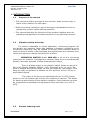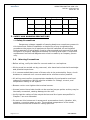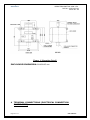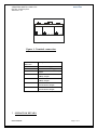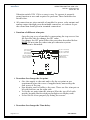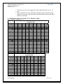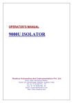
1
VIBRATION SWITCH-VSW-150 Ref No: mVS/om/101 Issue No: 03 masibus User Manual V I B RA T I O N S W I T C H V S W - 1 50 Masibus Automation And Instrumentation Pvt. Ltd. B/30, GIDC Electronics Estate, Sector-25, Gandhinagar-382044, Gujarat, India Phone No : 91 79 23287275 – 79 Fax No : 91 79 23287281, 82 Email: [email protected] Web: www.masibus.com masibus VIBRATION SWITCH-VSW-150 Ref No: mVS/om/101 Issue No: 03 Contents (1) INTRODUCTION …………………….…………………………….............03 1.1 1.2 1.3 Purpose of the manual Vibration switch overview Product ordering code (2) SAFETY AND WARNING PRECAUTIONS…………………….……….04 2.1 2.2 Safety Precautions Warning Precautions (3) MOUNTING DETAILS………………………….……………………………….06 (4) TERMINAL CONNECTIONS………………………………………………… 07 (5) OPERATION DETAILS……….………………………………………………….08 (5) Table for signal I/P Vs Display value …………………….…………....09 (7) SPECIFICATIONS…………………….………………………………………10 7.1 7.2 7.3 7.4 7.5 7.6 Electrical Specification Accuracy Mechanical Specification Environmental condition Output Calibration (8) MAINTENANCE………………………………………………………..……11 Figures Figure 1: Mounting Details………………………….…………………………………………………04 Figure 2: Terminal Connections……………………………………………………………………05 Note: Information in this manual is subject to change without prior notice or permission. Page 2 of 11 User Manual VIBRATION SWITCH-VSW-150 Ref No: mVS/om/101 Issue No: 03 masibus 1. INTRODUCTION 1.1 Purpose of the manual → This manual should be provided to the end user. Keep an extra copy or copies of the manual in a safe place. → Read this manual carefully to gain a thorough understanding of how to operate this product before starting operation. → This manual describes the functions of this product. Masibus does not guarantee the application of these functions for any particular purpose. 1.2 Vibration switch Overview For certain unattended or critical application, monitoring program will not identify any transient faults that happens in between monitoring cycle. Continuous monitoring may be needed to identify these transient faults to ensure corrective action to be developed and implemented at a schedule time, rather than having to disrupt operations for a failure. VIBRATION SWITCH Model VSW-150 is an on-line monitoring instrument for vibration. It accepts the vibration signal from an accelerometer display it and also generate 4-20Ma retransmission output. There is a Relay output in the vibration switch. Relay can be set to NO or NC (Factory Settable, Default – NO). Hysteresis is fix 1.o mm/s. Set point is settable through the range via trim pot inside the instruments. Time delay for relay on operation is settable via trim pot from 8 sec to 55 sec to avoid false tripping. The output 4-20 Ma can be interfaced with PLC or DCS system, which in turn can continuously monitor the condition of machine. This allows for alarming and trending of the machine condition. Some systems can even be programmed to shutdown the equipment either manually or by PLC or DCS). 1.3 Product ordering code User Manual Page 3 of 11 masibus Model No. VSW 150 VIBRATION SWITCH-VSW-150 Ref No: mVS/om/101 Issue No: 03 Vibration Range XX Analog Output X Mounting X 1R 12.5mm/s N None N None 2R 25 mm/s N None S Stud 3R 50 mm/s 1 4 to 20 mA P Pad 2. SAFETY AND WARNING PRECAUTIONS 2.1. Safety Precautions Dangerous voltages capable of causing death are sometimes present in this instrument. Before installation or beginning of any troubleshooting procedures the power to all equipment must be switched off and isolated. Units suspected of being faulty must be disconnected and removed first and brought to a properly equipped workshop for testing and repair. Component replacement and interval adjustments must be made by a company person only. 2.2 Warning Precautions → Before wiring, verify the label for correct model no. and options. → Wiring must be carried out by personnel, who have basic electrical knowledge and practical experience. → It is recommended that power of these units to be protected by fuses, circuit breakers or external over current rated at the minimum value possible. → All wiring must confirm to appropriate standards of good practice and local codes and regulations. Wiring must be suitable for voltage, current, and temperature rating of the system. → Beware not to over-tighten the terminal screws. → Unused control terminals should not be used as jumper points as they may be internally connected, causing damage to the unit. → Verify that the ratings of the output devices and the inputs as specified in Chapter 7 are not exceeded. → Do not use this instrument in areas such as excessive shock, vibration, dirt, moisture, corrosive gases or rain. The ambient temperature of the areas should not exceed the maximum rating specified. Page 4 of 11 User Manual VIBRATION SWITCH-VSW-150 Ref No: mVS/om/101 Issue No: 03 masibus → Provide Power from a single-phase instrument power supply. If there is a lot of noise in the power line, insert an insulating transformer into the primary side of the line and use a line filter on the secondary side. As counter measures against noise, do not place the primary and secondary power cables close to each other. Note: UNPACKING : Upon receipt of the shipment remove the unit form the carton and inspect the unit for shipping damage. If any damage due to transit, report and claim with the carrier. Write down the model number, serial number, and date code for future reference, when communicating with our Customer Support Division. 3 MOUNTING DETAILS User Manual Page 5 of 11 masibus VIBRATION SWITCH-VSW-150 Ref No: mVS/om/101 Issue No: 03 Figure 1: Mounting Detail ENCLOSURE DIMENSION: 80X82X85 mm 4 TERMINAL CONNECTIONS (ELECTRICAL CONNECTION GUIDELINES) Page 6 of 11 User Manual masibus VIBRATION SWITCH-VSW-150 Ref No: mVS/om/101 Issue No: 03 1 2 L N C NO NC RE+ RE- 3 4 5 6 7 Figure 2: Terminal connection Terminal Reference Pin L N C LIVE for AC Supply NEUTRAL for AC Supply COMMON Contact of Relay Output NO NORMALLY OPEN Contact of Relay Output NORMALLY CLOSE Contact of Relay Output NC 5 Description RE+ POSITIVE Terminal Retransmission Output of RE- NEGATIVE Terminal Retransmission Output of OPERATION DETAILS: User’s Manual Page 7 of 11 masibus VIBRATION SWITCH-VSW-150 Ref No: mVS/om/101 Issue No: 03 Vibration switch VSW 150 is so easy to use. To operate it properly some function at user end required to perform. Those functions are listed below. All connection are given outside of module for power ,relay output and analog output through green detachable connector, so connect as per the connection detail given in terminal connection. Function of different trim pots. Open the top cover of module by unscrewing the top screws. Saw the Pots like this for change the SET value. For change the SET point follow the procedure described below. NOTE: Do not trim the other trim pot otherwise system calibration is disturbed. Trim pot for Relay span calibration Trim pot for Time delay Trim pot for Relay Zero calibration Trim pot for SET Value Trim pot located near to 2 pin Allied female colored connector Trim pot for Calibration Trim pot located near to MKDS green colored connector Procedure for change the Set point. • Give the supply to the unit and to fix the set point as per requirement open the cover of supplied unit, unscrewing the four screw of the top. • Now display card is visible to the user. There are five trim pot on left side and two on the right side. • To fix the set point trim the trim pot SP(at the top of left side pots)by keeping black switch pressed(given at display card). • At last fit the cover properly by fitting the screws. Procedure for change the Time delay. Page 8 of 11 User Manual masibus VIBRATION SWITCH-VSW-150 Ref No: mVS/om/101 Issue No: 03 • • 6 P3 pot is use for to change the time delay from 8 sec to 55 sec. When trim pot P3 is rotated in clockwise direction the time delay is decrease and rotated in anticlockwise direction time delay is increase. Reference value of signal I/P Vs Display value. Table: 50mm/s Vs Signal level Amplitud e Frequency (Hz) (mVrms) 10 20 50 100 200 400 500 4.00 2.00 1.00 0.50 0.40 12.8 20.00 10.00 5.00 2.50 1.25 0.63 0.50 16 25.00 12.50 8.00 4.00 2.00 1.00 0.80 25.6 40.00 20.00 5.00 2.50 1.25 1.00 32 50.00 25.00 10.00 37.50 15.00 7.50 3.75 1.88 1.50 48 50.00 20.00 10.00 5.00 2.50 2.00 64 30.00 15.00 7.50 3.75 3.00 96 40.00 20.00 10.00 5.00 4.00 128 50.00 25.00 12.50 6.25 5.00 160 30.00 15.00 7.50 6.00 192 40.00 20.00 10.00 8.00 256 50.00 25.00 12.50 10.00 320 30.00 15.00 12.00 384 37.50 18.75 15.00 480 40.00 20.00 16.00 512 50.00 25.00 20.00 640 30.00 24.00 768 37.50 30.00 960 40.00 32.00 1024 50.00 40.00 1280 50.00 1600 Table: 4 to 20 Ma Vs signal of 50mm/s Amplitud e Frequency (Hz) (mVrms) 10 20 50 100 200 400 500 800 7.2 5.28 4.64 4.32 4.16 4.128 4.08 12.8 10.4 12 8 5.6 4.8 4.4 4.2 4.16 4.1 16 25.6 16.8 10.4 6.56 5.28 4.64 4.32 4.256 4.16 20 12 7.2 5.6 4.8 4.4 4.32 4.2 32 16 8.8 6.4 5.2 4.6 4.48 4.3 48 20 10.4 7.2 5.6 4.8 4.64 4.4 64 13.6 8.8 6.4 5.2 4.96 4.6 96 16.8 10.4 7.2 5.6 5.28 4.8 128 20 12 8 6 5.6 5 160 13.6 8.8 6.4 5.92 5.2 192 16.8 10.4 7.2 6.56 5.6 256 20 12 8 7.2 6 320 13.6 8.8 7.84 6.4 384 16 10 8.8 7 480 User’s Manual 800 0.25 0.31 0.50 0.63 0.94 1.25 1.88 2.50 3.13 3.75 5.00 6.25 7.50 9.38 10.00 12.50 15.00 18.75 20.00 25.00 31.25 1000 0.20 0.25 0.40 0.50 0.75 1.00 1.50 2.00 2.50 3.00 4.00 5.00 6.00 7.50 8.00 10.00 12.00 15.00 16.00 20.00 25.00 1000 4.064 4.08 4.128 4.16 4.24 4.32 4.48 4.64 4.8 4.96 5.28 5.6 5.92 6.4 Page 9 of 11 masibus 512 640 768 960 1024 1280 1600 7 VIBRATION SWITCH-VSW-150 Ref No: mVS/om/101 Issue No: 03 16.8 20 10.4 12 13.6 16 16.8 20 9.12 10.4 11.68 13.6 14.24 16.8 20 7.2 8 8.8 10 10.4 12 14 6.56 7.2 7.84 8.8 9.12 10.4 12 SPECIFICATIONS 7.1 ELECTRICAL SPECIFICATION • Supply Voltage : 90 to 270VAC • Sensor Excitation: 3.87 mA current,21 Voltage • Cut-Off frequency: High – 1 KHz, Low – 10Hz • RMS velocity: 12.5 mm/s ,25 mm/S or 50mm/S FSD (Factory set) • Retransmission Output: 4 to 20mA load 550ohm. 7.2 ACCURACY • Input to retransmission output: ± 5% of full span • Input to seven segment display: ± 5 % of full span 7.3 MECHANICAL SPECIFICATION • • • • Enclosure : ABS Weight: 350Grams Approx Enclosure Dimension : 80X82X85 mm wall mounted enclosure Mounting: Vertical mounting. 7 .4 ENVIRONMENTAL SPECIFICATION • Ambient Temperature: 0 to 55 °C • Humidity: 30 to 95% RH non-condensing • Storage Temperature: 0-80 °C 7.5 OUTPUTS 1) Relay Output: 230VAC, 2 A Relay can be set to NO or NC (Factory Settable, Default - NO) Hysteresis: 1.0 mm/s. Time Delay for relay on operation: Time Delay is settable via center trim pot from 8 sec to 55 sec. 2) Retransmission output: 4 – 20mA Note: Sensor open condition: When sensor is open or not connected with unit at . “ message on display and retransmission that time unit will shows “ 1 output is also less than1mA. Page 10 of 11 User Manual masibus VIBRATION SWITCH-VSW-150 Ref No: mVS/om/101 Issue No: 03 7.6 CALIBRATION • Zero and Span calibration for 4-20 mA output via trim port inside instrument. • Instrument Warm-up Time < 30 Min. Note: Instrument is factory calibrated. So, it does not require re-calibration. If user wants to re-calibration than it should be done only by trained technical persons only. 8 MAINTANCE Before installation or beginning of any troubleshooting procedures the power to all equipment must be switched off and isolated. Units suspected of being faulty must be disconnected and removed first and brought to a properly equipped workshop for testing and repair. Component replacement and interval adjustments must be made by a company person only. Masibus Automation & Instrumentation Pvt. Ltd. B/30, GIDC Electronics Estate, Sector-25, Gandhinagar-382044, Gujarat, India Email: [email protected] Web: www.masibus.com User’s Manual Page 11 of 11