1
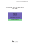
MITSUBISHI 16-BIT SINGLE-CHIP MICROCOMPUTER
M16C FAMILY
M16C/60
M16C/20
Series
<C language>
Programming Manual
http://www.infomicom.maec.co.jp/indexe.htm
Before using this material, please visit the above website to confirm that this is the most
current document available.
REV. A1
Revision date: Nov. 12, 2001
Keep safety first in your circuit designs!
•
Mitsubishi Electric Corporation puts the maximum effort into making semiconductor products better and more reliable, but there is always the possibility that trouble may occur with
them. Trouble with semiconductors may lead to personal injury, fire or property damage.
Remember to give due consideration to safety when making your circuit designs, with appropriate measures such as (i) placement of substitutive, auxiliary circuits, (ii) use of nonflammable material or (iii) prevention against any malfunction or mishap.
Notes regarding these materials
•
•
•
•
•
•
•
•
These materials are intended as a reference to assist our customers in the selection of the
Mitsubishi semiconductor product best suited to the customer's application; they do not
convey any license under any intellectual property rights, or any other rights, belonging to
Mitsubishi Electric Corporation or a third party.
Mitsubishi Electric Corporation assumes no responsibility for any damage, or infringement
of any third-party's rights, originating in the use of any product data, diagrams, charts,
programs, algorithms, or circuit application examples contained in these materials.
All information contained in these materials, including product data, diagrams, charts, programs and algorithms represents information on products at the time of publication of these
materials, and are subject to change by Mitsubishi Electric Corporation without notice due
to product improvements or other reasons. It is therefore recommended that customers
contact Mitsubishi Electric Corporation or an authorized Mitsubishi Semiconductor product
distributor for the latest product information before purchasing a product listed herein.
The information described here may contain technical inaccuracies or typographical errors.
Mitsubishi Electric Corporation assumes no responsibility for any damage, liability, or other
loss rising from these inaccuracies or errors.
Please also pay attention to information published by Mitsubishi Electric Corporation by
various means, including the Mitsubishi Semiconductor home page (http://
www.mitsubishichips.com).
When using any or all of the information contained in these materials, including product
data, diagrams, charts, programs, and algorithms, please be sure to evaluate all information as a total system before making a final decision on the applicability of the information
and products. Mitsubishi Electric Corporation assumes no responsibility for any damage,
liability or other loss resulting from the information contained herein.
Mitsubishi Electric Corporation semiconductors are not designed or manufactured for use
in a device or system that is used under circumstances in which human life is potentially at
stake. Please contact Mitsubishi Electric Corporation or an authorized Mitsubishi Semiconductor product distributor when considering the use of a product contained herein for any
specific purposes, such as apparatus or systems for transportation, vehicular, medical,
aerospace, nuclear, or undersea repeater use.
The prior written approval of Mitsubishi Electric Corporation is necessary to reprint or reproduce in whole or in part these materials.
If these products or technologies are subject to the Japanese export control restrictions,
they must be exported under a license from the Japanese government and cannot be imported into a country other than the approved destination.
Any diversion or reexport contrary to the export control laws and regulations of Japan and/
or the country of destination is prohibited.
Please contact Mitsubishi Electric Corporation or an authorized Mitsubishi Semiconductor
product distributor for further details on these materials or the products contained therein.
Preface
This programming manual is written about
the M16C/60, M16C/20 series of Mitsubishi
CMOS 16-bit microcomputers explaining
the basics of the C language and describing
how to put your program into ROM and how
to use the real-time OS (MR30) while using
NC30, the C compiler for the M16C/60,
M16C/20 series. This manual will prove
helpful to you as a guide to the C language,
as well as a textbook to be referenced when
creating a C language program.
For details about hardware and
development support tools available for
each type of microcomputer in the M16C/
60, M16C/20 series, please refer to the
user's manual and instruction or reference
manuals supplied with your microcomputer.
Chapter 1 Introduction to C Language
1
Chapter 2 ROM'ing Technology
2
Chapter 3 Using Real-time OS (MR30)
3
Appendices
Appendices
Guide to Using This Manual
This manual is a programming manual for NC30, the C compiler for the M16C/60, M16C/20
series.
Knowledge of the M16C/60, M16C/20 series microcomputer architecture and the assembly
language is required before using this manual.
This manual consists of three chapters. The following provides an approximate guide to using
this manual:
• Those who learn the C language for the first time → Begin with Chapter 1.
• Those who wish to know NC30 extended functions → Begin with Chapter 2.
• Those who use the real-time OS, MR30 → Begin with Chapter 3.
Furthermore, appendices are included at the end of this manual: "Functional Comparison
between NC30 and NC77", "nc30 Command Reference", and "Q & A".
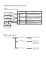
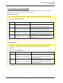
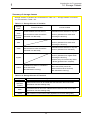
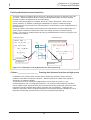
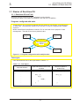
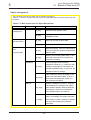
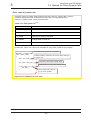
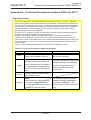
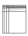
M16C Family-related document list
Usages
(Microcomputer development flow)
Type of document
Outline design
of system
Hardware
Selection of
microcomputer
Data sheet and
data book
User’s manual
Hardware
development
Software
development
Software
Detail design
of system
Contents
Hardware specifications (pin assignment,
memory map, specifications of peripheral
functions, electrical characteristics, timing
charts)
Detailed description about hardware specifications, operation, and application examples
(connection with peripherals, relationship
with software)
Programming
manual
Method for creating programs using assembly and C languages
Software manual
Detailed description about operation of each
instruction (assembly language)
System
evaluation
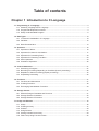
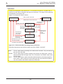
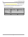
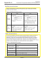
M16C Family Line-up
M16C Family
M16C/80 Series
M16C/80 Group
M16C/60 Series
M16C/60 Group
M16C/61 Group
M16C/62 Group
M16C/20 Series
M16C/20 Group
M16C/21 Group
Table of contents
Chapter 1 Introduction to C Language
1.1 Programming in C Language ........................................................................................................3
1.1.1 Assembly Language and C Language .................................................................................... 3
1.1.2 Program Development Procedure ........................................................................................... 4
1.1.3 Easily Understandable Program ............................................................................................. 6
1.2 Data Types ....................................................................................................................................10
1.2.1 "Constants" Handleable in C Language .................................................................................10
1.2.2 Variables ................................................................................................................................12
1.2.3 Data Characteristics ...............................................................................................................14
1.3 Operators ......................................................................................................................................16
1.3.1
1.3.2
1.3.3
1.3.4
1.3.5
1.3.6
Operators of NC30 ................................................................................................................ 16
Operators for Numeric Calculations ...................................................................................... 17
Operators for Processing Data ............................................................................................. 20
Operators for Examining Condition ........................................................................................23
Other Operators .................................................................................................................... 24
Priorities of Operators ........................................................................................................... 26
1.4 Control Statements ......................................................................................................................27
1.4.1
1.4.2
1.4.3
1.4.4
Structuring of Program ........................................................................................................... 27
Branching Processing Depending on Condition (branch processing) ...................................28
Repetition of Same Processing (repeat processing) ............................................................. 32
Suspending Processing .........................................................................................................35
1.5 Functions ......................................................................................................................................37
1.5.1 Functions and Subroutines .................................................................................................... 37
1.5.2 Creating Functions ................................................................................................................ 38
1.5.3 Exchanging Data between Functions ....................................................................................40
1.6 Storage Classes ...........................................................................................................................41
1.6.1 Effective Range of Variables and Functions ..........................................................................41
1.6.2 Storage Classes of Variables .................................................................................................42
1.6.3 Storage Classes of Functions ............................................................................................... 44
1.7 Arrays and Pointers .................................................................................................................... 46
1.7.1
1.7.2
1.7.3
1.7.4
1.7.5
1.7.6
Arrays .................................................................................................................................... 46
Creating an Array .................................................................................................................. 47
Pointers ..................................................................................................................................49
Using Pointers ........................................................................................................................51
Placing Pointers into an Array ............................................................................................... 53
Table Jump Using Function Pointer ...................................................................................... 55
1.8 Struct and Union ......................................................................................................................... 57
1.8.1 Struct and Union .................................................................................................................... 57
1.8.2 Creating New Data Types ...................................................................................................... 58
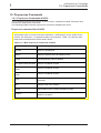
1.9 Preprocess Commands ...............................................................................................................62
1.9.1
1.9.2
1.9.3
1.9.4
Preprocess Commands of NC30 ........................................................................................... 62
Taking in A File .......................................................................................................................63
Macro Definition .................................................................................................................... 64
Conditional Compile ...............................................................................................................66
Chapter 2 ROM'ing Technology
2.1 Memory Mapping .........................................................................................................................71
2.1.1
2.1.2
2.1.3
2.1.4
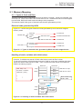
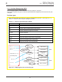
Types of Code and Data ........................................................................................................71
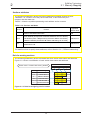
Sections Managed by NC30 .................................................................................................. 72
Control of Memory Mapping .................................................................................................. 74
Controlling Memory Mapping of Struct .................................................................................. 76
2.2 Startup Program ...........................................................................................................................78
2.2.1 Roles of Startup Program ......................................................................................................78
2.2.2 Estimating Stack Sizes Used .................................................................................................80
2.2.3 Creating Startup Program ......................................................................................................83
2.3 Extended Functions for ROM'ing Purposes ............................................................................. 90
2.3.1
2.3.2
2.3.3
2.3.4
Efficient Addressing ...............................................................................................................90
Handling of Bits ......................................................................................................................94
Control of I/O Interface ........................................................................................................... 96
When Cannot Be Written in C Language ...............................................................................98
2.4 Linkage with Assembly Language .......................................................................................... 100
2.4.1 Interface between Functions ............................................................................................... 100
2.4.2 Calling Assembly Language from C Language ................................................................... 105
2.4.3 Calling C Language from Assembly Language .................................................................... 111
2.5 Interrupt Processing .................................................................................................................. 112
2.5.1 Writing Interrupt Processing Functions ................................................................................ 112
2.5.2 Registering Interrupt Processing Functions ......................................................................... 115
2.5.3 Example for Writing Interrupt Processing Function.............................................................. 116
Chapter 3 Using Real-time OS (MR30)
3.1 Basics of Real-time OS ............................................................................................................. 121
3.1.1
3.1.2
3.1.3
3.1.4
Real-time OS and Task .......................................................................................................
Functions of Real-time OS ..................................................................................................
Interrupt Management .........................................................................................................
Special Handlers .................................................................................................................
121
124
127
130
3.2 Method for Using System Calls ............................................................................................... 131
3.2.1 MR30's System Calls .......................................................................................................... 131
3.2.2 Writing a System Call.......................................................................................................... 132
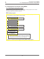
3.3 Development Procedures Using MR30 ..................................................................................... 135
3.3.1 Files Required during Development .................................................................................... 135
3.3.2 Flow of Development Using MR30 ..................................................................................... 140
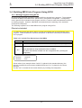
3.4 Building MR30 into Program Using NC30 .............................................................................. 141
3.4.1
3.4.2
3.4.3
3.4.4
Writing Program Using NC30 ..............................................................................................
Writing Tasks using NC30 ...................................................................................................
Writing Interrupt Handler .....................................................................................................
Writing Cyclic and Alarm Handlers ......................................................................................
141
143
147
151
Appendices
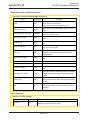
Appendix A. Functional Comparison between NC30 and NC77 ..................................... Appendix-3
Appendix B. NC30 Command Reference .......................................................................... Appendix-6
Appendix C. Questions & Answers ................................................................................. Appendix-12
Table of contents for example
Chapter 1 Introduction to C Language
1.1 Programming in C Language
1.2 Data Types
1.3 Operators
1.4 Control Statements ......................................................................................................................27
Example 1.4.1
Example 1.4.2
Example 1.4.3
Example 1.4.4
Example 1.4.5
Example 1.4.6
Count Up (if-else statement) .................................................................................. 28
Switchover of Arithmetic Operations-1 (else-if statement) ......................................29
Switchover of Arithmetic Operations-2 (switch-case statement) .............................30
Finding Sum Total -1 (while statement) ...................................................................32
Finding Sum Total -2 (for statement) ...................................................................... 33
Finding Sum Total -3 (do-while statement) .............................................................34
1.5 Functions ......................................................................................................................................37
Example 1.5.1 Finding Sum of Integers (example for writing a function) ........................................40
1.6 Storage Classes
1.7 Arrays and Pointers .................................................................................................................... 46
Example 1.7.1 Finding Total Age of a Family -1 ............................................................................. 46
Example 1.7.2 Finding Total Age of a Family -2 ............................................................................. 47
Example 1.7.3 Switching Arithmetic Operations Using Table Jump............................................... 56
1.8 Struct and Union
1.9 Preprocess Commands
Chapter 2 ROM'ing Technology
2.1 Memory Mapping
2.2 Startup Program
2.3 Extended Functions for ROM'ing Purposes ............................................................................. 90
Example 2.3.1 Defining SFR Area Using "#pragma ADDRESS" ....................................................97
2.4 Linkage with Assembly Language .......................................................................................... 100
Example 2.4.1 Calling Subroutine ................................................................................................ 107
Example 2.4.2 Calling a Subroutine by Table Jump .................................................................... 109
Example 2.4.3 A Little Different Way to Use Table Jump .............................................................. 110
2.5 Interrupt Processing
Chapter 3 Using Real-time OS (MR30)
3.1 Basics of Real-time OS
3.2 Method for Using System Calls
3.3 Development Procedures Using MR30
3.4 Building MR30 into Program Using NC30
Appendices
Appendix A. Functional Comparison between NC30 and NC77
Appendix B. NC30 Command Reference
Appendix C. Questions & Answers
Chapter 1
Introduction to C Language
1.1
1.2
1.3
1.4
1.5
1.6
1.7
1.8
1.9
Programming in C Language
Data Types
Operators
Control Statements
Functions
Storage Classes
Arrays and Pointers
Struct and Union
Preprocess Commands
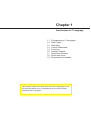
This chapter explains for those who learn the C language for the
first time the basics of the C language that are required when
creating a built-in program.
Introduction to C Language
1
1.1 Programming in C Language
2
Introduction to C Language
1
1.1 Programming in C Language
1.1 Programming in C Language
1.1.1 Assembly Language and C Language
As the scale of microcomputer-based systems increased in recent years, a program's productivity
and maintainability became to attract the attention of the people concerned. At the same time,
more and more programs have become to be developed in the C language, instead of using the
conventional assembly language.
The following explains the main features of the C language and describes how to write a program
in the C language.
Features of the C language
(1) An easily traceable program can be written.
The basics of structured programming, i.e., "sequential processing", "branch
processing", and "repeat processing", can all be written in a control statement. For this
reason, it is possible to write a program whose flow of processing can easily be traced.
(2) A program can easily be divided into modules.
A program written in the C language consists of basic units called "functions". Since
functions have their parameters highly independent of others, a program can easily be
made into parts and can easily be reused. Furthermore, modules written in the
assembly language can be incorporated into a C language program directly without
modification.
(3) An easily maintainable program can be written.
For reasons (1) and (2) above, the program after being put into operation can easily be
maintained. Furthermore, since the C language is based on standard specifications
(ANSI standard(Note)), a program written in the C language can be ported into other
types of microcomputers after only a minor modification of the source program.
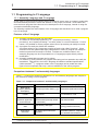
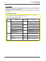
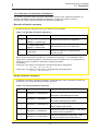
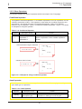
Comparison between C and assembly languages
Table 1.1.1 outlines the differences between the C and assembly languages with respect to
the method for writing a source program.
Table 1.1.1 Comparison between C and Assembly Languages
Basic unit of
program (Method of
description)
Format
Discrimination
between uppercase
and lowercase
Allocation of data
area
Input/output
instruction
C language
Assembly language
Function (Function name ( ) { })
Subroutine (Subroutine name:)
Free format
1 instruction in 1 line
Uppercase and lowercase are
discriminated (Normally written
in lowercase)
Not discriminated
Specified by "data type"
Specified by a number of bytes
(using pseudo-instruction)
No input/output instructions
available
Input/output instructions
available (However, it depends
on hardware and software.)
Note: This refers to standard specifications stipulated for the C language by the American National Standards Institute (ANSI)
to maintain the portability of C language programs.
3
Introduction to C Language
1
1.1 Programming in C Language
1.1.2 Program Development Procedure
An operation to translate a source program written in the C language into a machine language
program is referred to as "compiling". The software provided for performing this operation is
called a "compiler".
This section explains the procedure for developing a program by using NC30, the C compiler for
the M16C/60, M16C/20 series of Mitsubishi single-chip microcomputers.
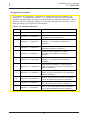
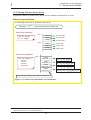
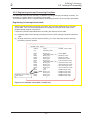
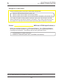
NC30 product list
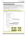
Figure 1.1.1 lists the products included in NC30, the C compiler for the M16C/60, M16C/20
series of Mitsubishi single-chip microcomputers.
Compile driver
(nc30)
It starts up the compiler, assembler, or linker.
Preprocessor
(cpp30)
It processes macro and conditional compiling.
Compiler main unit
(ccom30)
NC30
product
package
It converts C language source files into assembly
language source files.
Stack size calculating utility
(stk30)
Sample startup program
(ncrt0.a30/sect30.inc)
Standard libraries
Standard library source files
Figure 1.1.1 NC30 product list
4
It calculates the amount of
stacks used.
Introduction to C Language
1
1.1 Programming in C Language
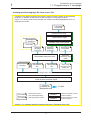
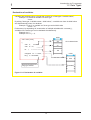
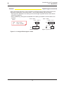
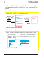
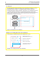
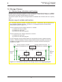
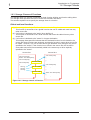
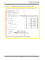
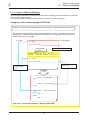
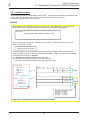
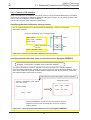
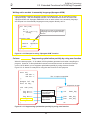
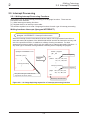
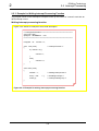
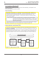
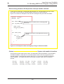
Creating machine language file from source file
Creation of a machine language file requires startup programs written in the assembly
language, in addition to the source file that contains a C language program.
Figure 1.1.2 shows a tool chain necessary to create a machine language file from a C
language source file.
C language
source file
Compile driver nc30
Preprocessor ccp30
Startup programs
sect30.inc
Compiler main unit ccom30
ncrt0.a30
Assembly
language
source file
Assembly
language
source file
Relocatable assembler as30
Libraries
Relocatable
file
Relocatable
file
Stack usage
information
file
Stack size
calculating utility
stk30
Stack usage
calculation result
display file
Linkage editor ln30
Load module converter lmc30
Machine
language file
File name
: Files prepared by the
Software
user (including libraries)
File name
To ROM
: Files generated by NC30
Software
: Software included in NC30
product package
: Software included in AS30
product package
Figure 1.1.2 Creating machine language file from C language source file
5
Introduction to C Language
1
1.1 Programming in C Language
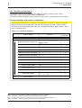
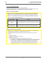
1.1.3 Easily Understandable Program
Since there is no specific format for C language programs, they can be written in any desired way
only providing that some rules stipulated for the C language are followed. However, a program
must be easily readable and must be easy to maintain. Therefore, a program must be written in
such a way that everyone, not just the one who developed the program, can understand it.
This section explains some points to be noted when writing an "easily understandable" program.
Rules on C language
The following lists the six items that need to be observed when writing a C language
program:
(1) As a rule, use lowercase English letters to write a program.
(2) Separate executable statements in a program with a semicolon ";".
(3) Enclose execution units of functions or control statements with brackets "{" and "}"
(4) Functions and variables require type declaration.
(5) Reserved words cannot be used in identifiers (e.g., function names and variable
names).
(6) Write comments between "/∗" and "∗/".
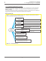
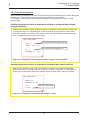
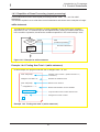
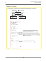
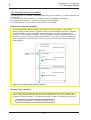
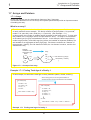
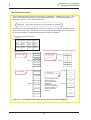
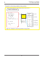
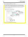
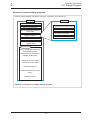
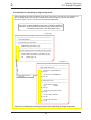
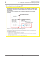
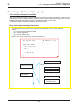
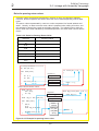
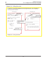
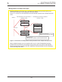
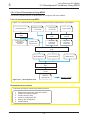
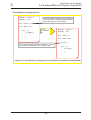
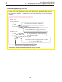
Configuration of C language source file
Figure 1.1.3 schematically shows a configuration of a general C language source file. For
each item in this file, refer to the section indicated with an arrow.
Reading header file
Refer to 1.9, "Preprocess Commands".
Type declaration of functions used;
Refer to 1.5, "Functions".
Macro definition
Refer to 1.9, "Preprocess Commands".
Declaration of external variables
Refer to 1.2, "Date Types" and 1.6,
"Storage Classes".
Type function name (dummy argument, ...)
{
Declaration of internal variables;
Refer to 1.5, "Functions".
Refer to 1.2, "Date Types" and 1.6,
"Storage Classes".
Refer to 1.3, "Operators" and 1.4,
"Control Statements".
Executable statement;
}
••
•
Figure 1.1.3 Configuration of C language source file
6
Introduction to C Language
1
1.1 Programming in C Language
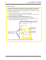
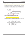
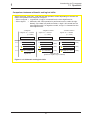
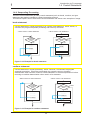
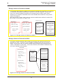
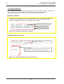
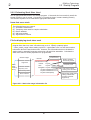
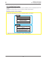
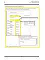
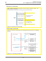
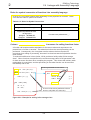
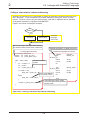
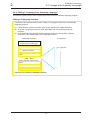
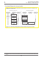
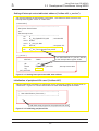
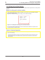
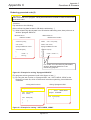
Programming style
To increase the maintainability of a program, it is necessary that a template for program list
is determined by consultation between those who develop the program. By sharing this
template as a "programming style" among the developers, it is made possible to write a
source program that can be understood and maintained by anyone. Figure 1.1.4 shows an
example of a programming style.
(1) Create a function separately for each functionality of the program.
(2) Limit processing within one function unless specifically necessary. (A size not larger
than 50 lines or so is recommended.)
(3) Do not write multiple executable statements in one line.
(4) Indent each processing block successively (normally 4 tab stops).
(5) Clarify the program flow by writing comment statements as appropriate.
(6) When creating a program from multiple source files, place the common part of the
program in an independent separate file and share it.
Enclose a comment statement with "/∗" and "∗/ ".
/∗
Test program
unsigned int
∗/
ram1;
main()
{
'main' processing
char
Indentation
Enclose a set of processing
with brackets "{" and "}"
a;
while(1){
if(a==ram1) {
break ;
Indentation }
else{
a=ram1;
}
}
}
'while' processing
Figure 1.1.4 Example of programming style of C language program
7
Introduction to C Language
1
1.1 Programming in C Language
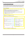
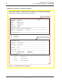
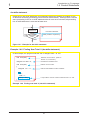
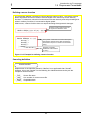
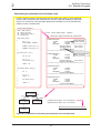
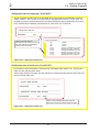
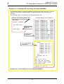
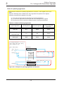
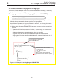
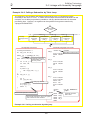
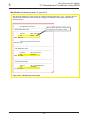
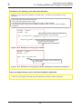
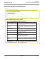
Method for writing a comment statement
The method for writing a comment statement constitutes an important point in writing an
easily readable program. Program flow can be clarified by, for example, indicating the
functionality of a file or that of a function as the header.
Example of file header
/∗ ""FILE COMMENT"" ∗∗∗∗∗∗∗∗∗∗∗∗∗∗∗∗∗∗∗∗∗∗∗∗∗∗∗∗∗∗∗∗∗∗∗∗∗∗∗∗∗∗∗∗∗∗∗∗∗∗∗∗∗∗∗∗∗∗∗∗∗∗∗∗∗∗
∗SystemName : Test program
∗ FileName
: TEST.C
∗ Version
: 1.00
∗ CPU
: M30600M8-XXXFP
∗ Compiler
: NC30 (Ver.1.00)
∗ OS
: Unused
∗ Programmer : XXXX
∗∗∗∗∗∗∗∗∗∗∗∗∗∗∗∗∗∗∗∗∗∗∗∗∗∗∗∗∗∗∗∗∗∗∗∗∗∗∗∗∗∗∗∗∗∗∗∗∗∗∗∗∗∗∗∗∗∗∗∗∗∗∗∗∗∗∗∗∗∗∗∗∗∗∗∗∗∗∗∗∗∗∗∗∗∗∗
∗ Copyright, XXXX xxxxxxxxxxxxxxxxx CORPORATION
∗∗∗∗∗∗∗∗∗∗∗∗∗∗∗∗∗∗∗∗∗∗∗∗∗∗∗∗∗∗∗∗∗∗∗∗∗∗∗∗∗∗∗∗∗∗∗∗∗∗∗∗∗∗∗∗∗∗∗∗∗∗∗∗∗∗∗∗∗∗∗∗∗∗∗∗∗∗∗∗∗∗∗∗∗∗∗
∗ History
: XXXX.XX.XX
: Start
∗ ""FILE COMMENT END"" ∗∗∗∗∗∗∗∗∗∗∗∗∗∗∗∗∗∗∗∗∗∗∗∗∗∗∗∗∗∗∗∗∗∗∗∗∗∗∗∗∗∗∗∗∗∗∗∗∗∗∗∗∗∗∗∗∗∗∗∗∗∗∗∗/
/∗ ""Prototype declaration"" ∗∗∗∗∗∗∗∗∗∗∗∗∗∗∗∗∗∗∗∗∗∗∗∗∗∗∗∗∗∗∗∗∗∗∗∗∗∗∗∗∗∗∗∗∗∗∗∗∗∗∗∗∗∗∗∗∗∗∗∗∗∗∗∗∗/
void
main ( void ) ;
void
key_in ( void ) ;
Example of function header
void
key_out ( void ) ;
/∗ ""FUNC COMMENT"" ∗∗∗∗∗∗∗∗∗∗∗∗∗∗∗∗∗∗∗∗∗∗∗∗∗∗∗∗∗∗∗∗∗∗∗∗∗∗∗∗∗∗∗∗∗∗∗∗∗∗∗∗∗∗∗∗∗∗∗∗∗∗∗∗∗∗
∗ Function name : main()
∗ --------------------------------------------------------------------------------------------------------------------------------∗ Declaration
: void main (void)
∗ --------------------------------------------------------------------------------------------------------------------------------∗ Functionality : Overall control
∗ --------------------------------------------------------------------------------------------------------------------------------∗ Argument
: void
∗ --------------------------------------------------------------------------------------------------------------------------------∗ Return value : void
∗ --------------------------------------------------------------------------------------------------------------------------------∗ Functions used : voidkey_in ( void )
; Input function
∗
: voidkey_out ( void )
; Output function
∗ ""FUNC COMMENT END"" ∗∗∗∗∗∗∗∗∗∗∗∗∗∗∗∗∗∗∗∗∗∗∗∗∗∗∗∗∗∗∗∗∗∗∗∗∗∗∗∗∗∗∗∗∗∗∗∗∗∗∗∗∗∗∗∗∗∗∗∗∗/
void
main ( void )
{
while(1){
/∗ Endless loop ∗/
key_in() ;
/∗ Input processing ∗/
key_out();
/∗ Output processing ∗/
}
}
Figure 1.1.5 Example for using comments
8
Introduction to C Language
1
1.1 Programming in C Language
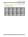
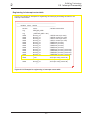
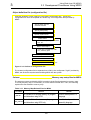
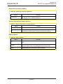
Column
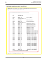
Reserved words of NC30
The words listed in Table 1.1.2 are reserved for NC30. Therefore, these words cannot be
used in variable or function names.
Table 1.1.2 Reserved Words of NC30
_asm
const
far
register
switch
_far
continue
float
return
typedef
_near
default
for
short
union
asm
do
goto
signed
unsigned
auto
double
if
sizeof
void
break
else
int
static
volatile
case
enum
long
struct
while
char
extern
near
9
Introduction to C Language
1
1.2 Data Types
1.2 Data Types
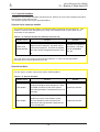
1.2.1 "Constants" Handleable in C Language
Four types of constants can be handled in the C language: "integer", "real", "single character",
and "character string".
This section explains the method of description and the precautions to be noted when using each
of these constants.
Integer constants
Integer constants can be written using one of three methods of numeric representation:
decimal, hexadecimal, and octal. Table 1.2.1 shows each method for writing integer
constants. Constant data are not discriminated between uppercase and lowercase.
Table 1.2.1 Method for Writing Integer Constants
Numeration
Method of writing
Example
Decimal
Normal mathematical notation (nothing added)
127 , +127 , –56
Hexadecimal
Numerals are preceded by 0x or 0X (zero eks).
0x3b , 0X3B
Numerals are preceded by 0 (zero).
07 , 041
Octal
Real constants (Floating-point constants)
Floating-point constants refer to signed real numbers that are expressed in decimal. These
numbers can be written by usual method of writing using the decimal point or by
exponential notation using "e" or "E".
• Usual method of writing
Example: 175.5, -0.007
• Exponential notation
Example: 1.755e2, -7.0E-3
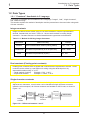
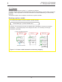
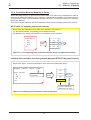
Single-character constants
Single-character constants must be enclosed with single quotations ('). In addition to
alphanumeric characters, control codes can be handled as single-character constants.
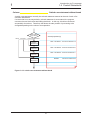
Inside the microcomputer, all of these constants are handled as ASCII code, as shown in
Figure 1.2.1.
Memory
Memory
1
Integer
constant
Integer
0x01
'1'
Single-character
constant
Figure 1.2.1 Difference between 1 and '1'
10
0x31
ASCII code
Introduction to C Language
1
1.2 Data Types
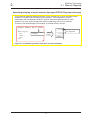
Character string constants
A row of alphanumeric characters or control codes enclosed with double quotations (") can
be handled as a character string constant. Character string constants have the null
character "\0" automatically added at the end of data to denote the end of the character
string.
Example: "abc", "012\n", "Hello!"
Memory
Memory
{ 'a' , 'b' }
'a'
A set of singlecharacter
constants
'b'
'a'
"ab"
2 bytes of
data area
are used.
Character
string
constant
'b'
3 bytes of
data area
are used.
'\0'
?
Null code
Figure 1.2.2 Difference between {'a', 'b'} and "ab"
Column
List of control codes (escape sequence)
The following shows control codes (escape sequence) that are frequently used in the C
language.
Table 1.2.2 Escape Sequence in C Language
Notation
Content
Notation
Content
\f
Form feed (FF)
\'
Single quotation
\n
New line (NL)
\"
Double quotation
\r
Carriage return (CR)
\x constant
value
Hexadecimal
\t
Horizontal tab (HT)
\ constant
value
Octal
\\
\ symbol
\0
Null code
11
Introduction to C Language
1
1.2 Data Types
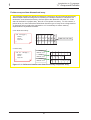
1.2.2 Variables
Before a variable can be used in a C language program, its "data type" must first be declared in
the program. The data type of a variable is determined based on the memory size allocated for
the variable and the range of values handled.
This section explains the data types of variables that can be handled by NC30 and how to declare
the data types.
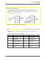
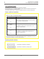
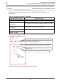
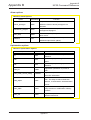
Basic data types of NC30
Table 1.2.3 lists the data types that can be handled in NC30. Descriptions enclosed with ( ) in
the table below can be omitted when declaring the data type.
Table 1.2.3 Basic Data Types of NC30
Data type
Bit length
(unsigned) char
8 bits
signed char
16 bits
(signed) short (int)
0 to 255
0 to 65535
- 32768 to 32767
unsigned int
16 bits
(signed) int
0 to 65535
- 32768 to 32767
unsigned long (int)
32 bits
(signed) long (int)
Real
expressed
-128 to 127
unsigned short (int)
Integer
Range of values that can be
0 to 4294967295
- 2147483648 to 2147483647
float
32 bits
Number of significant digits: 9
double
64 bits
Number of significant digits: 17
long double
64 bits
Number of significant digits: 17
12
Introduction to C Language
1
1.2 Data Types
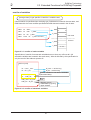
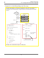
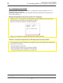
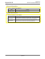
Declaration of variables
Variables are declared using a format that consists of a "data type ∆ variable name;".
Example: To declare a variable a as char type
char a;
By writing "data type ∆ variable name = initial value;", a variable can have its initial value
set simultaneously when it is declared.
Example: To set 'A' to variable a of char type as its initial value
char a = 'A';
Furthermore, by separating an enumeration of multiple variables with a comma (,),
variables of the same type can be declared simultaneously.
Example: int i, j;
Example: inti = 1, j = 2;
8 bits
void main ( void )
a
XX
b
'A'
i
XX
{
char
a;
char
b = 'A' ;
int
i;
unsigned
long
int
XX: Indeterminate
k = 500 ;
8 bits
n = 0x10000L ;
k
Denotes that this is the
long type of data.
500
n 0x10000L
Figure 1.2.3 Declaration of variables
13
Introduction to C Language
1
1.2 Data Types
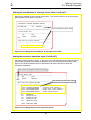
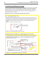
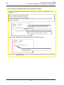
1.2.3 Data Characteristics
When declaring a variable or constant, NC30 allows its data characteristic to be written along with
the data type. The specifier used for this purpose is called the "type qualifier".
This section explains the data characteristics handled by NC30 and how to specify a data
characteristic.
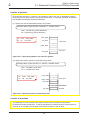
Specifying that the variable or constant is singed or unsigned data (singed/
unsigned qualifier)
Write the type qualifier "signed" when the variable or constant to be declared is signed data
or "unsigned" when it is unsigned data. If neither of these type specifiers is written when
declaring a variable or constant, NC30 assumes that it is signed data for only the data type
char, or unsigned data for all other data types.
void main ( void )
{
char a ;
signed char s_a ;
int b ;
unsigned
Synonymous with "unsigned char a";
Synonymous with "signed int b";
int
u_b ;
••
•
}
Figure 1.2.4 Example for writing type qualifiers "signed" and "unsigned"
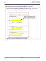
Specifying that the variable or constant is constant data (const qualifier)
Write the type qualifier "const" when the variable or constant to be declared is the data
whose value does not change at all even when the program is executed. If a description is
found in the program that causes this constant data to change, NC30 outputs a warning.
void main ( void )
{
char a = 10 ;
constcharc_a = 20 ;
a=5;
c_a = 5 ;
Warning is generated.
}
Figure 1.2.5 Example for writing the type qualifier "const"
14
Introduction to C Language
1
1.2 Data Types
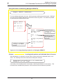
Inhibiting optimization by compiler (volatile qualifier)
NC30 optimizes the instructions that do not have any effect in program processing, thus
preventing unnecessary instruction code from being generated. However, there are some
data that are changed by an interrupt or input from a port irrespective of program
processing. Write the type qualifier "volatile" when declaring such data. NC30 does not
optimize the data that is accompanied by this type qualifier and outputs instruction code for
it.
void main ( void )
{
char port1 ;
volatile char port2 ;
Optimized and no code is output
because it is only read.
port1 ;
port2 ;
Code is output without optimizing.
}
Figure 1.2.6 Example for writing the type qualifier "volatile"
Column
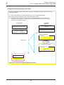
Syntax of declaration
When declaring data, write data characteristics using various specifiers or qualifiers along
with the data type. Figure 1.2.7 shows the syntax of a declaration.
Declaration specifier
Storage class
specifier
(described later)
Type
qualifier
Type
specifier
static
register
auto
extern
unsigned
signed
const
volatile
int
char
float
struct
union
Figure 1.2.7 Syntax of declaration
15
Declarator
(data name)
dataname
Introduction to C Language
1
1.3 Operators
1.3 Operators
1.3.1 Operators of NC30
NC30 has various operators available for writing a program.
This section describes how to use these operators for each specific purpose of use (not including
address and pointer operators(Note)) and the precautions to be noted when using them.
Operators usable in NC30
Table 1.3.1 lists the operators that can be used in NC30.
Table 1.3.1 Operators Usable in NC30
Monadic arithmetic operators
++
––
+
–
<<
>>
Bitwise operators
&
|
^
~
Relational operators
>
<
>=
<=
==
!=
&&
||
!
=
+=
-=
∗*=
/=
%=
Binary arithmetic operators
Shift operators
Logical operators
Assignment operators
Conditional operator
–
∗*
/
%
?:
sizeof operator
sizeof( )
Cast operator
(type)
Address operator
&
Pointer operator
∗*
Comma operator
,
Note: For address and pointer operators, refer to Section 1.7, "Arrays and Pointers".
16
<<=
>>=
&=
|=
^=
Introduction to C Language
1
1.3 Operators
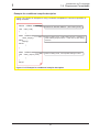
1.3.2 Operators for Numeric Calculations
The primary operators used for numeric calculations consist of the "arithmetic operators" to
perform calculations and the "assignment operators" to store the results in memory.
This section explains these arithmetic and assignment operators.
Monadic arithmetic operators
Monadic arithmetic operators return one answer for one variable.
Table 1.3.2 Monadic Arithmetic Operators
Operator
Description format
Content
++
++ variable (prefix type)
variable ++ (postfix type)
Increments the value of an expression.
--
-- variable (prefix type)
variable -- (postfix type)
Decrements the value of an expression.
-
- expression
Returns the value of an expression after
inverting its sign.
When using the increment operator (++) or decrement operator (--) in combination with a
assignment or relational operator, note that the result of operation may vary depending on
which type, prefix or postfix, is used when writing the operator.
<Examples>
Prefix type: The value is incremented or decremented before assignment.
b = ++a; → a = a + 1; b = a;
Postfix type: The value is incremented or decremented after assignment.
b = a++; → b = a; a = a + 1;
Binary arithmetic operators
In addition to ordinary arithmetic operations, these operators make it possible to obtain the
remainder of an "integer divided by integer" operation.
Table 1.3.3 Binary Arithmetic Operators
Operator
Description format
Content
+
expression 1 + expression 2
Returns the sum of expression 1 and
expression 2 after adding their values.
−
expression 1 - expression 2
Returns the difference between expressions 1
and 2 after subtracting their values.
∗∗
expression 1 ∗ expression 2
Returns the product of expressions 1 and 2
after multiplying their values.
/
expression 1 / expression 2
Returns the quotient of expression 1 after diving
its value by that of expression 2.
%
expression 1 % expression 2
Returns the remainder of expression 1 after
dividing its value by that of expression 2.
17
Introduction to C Language
1
1.3 Operators
Assignment operators
The operation of "expression 1 = expression 2" assigns the value of expression 2 for
expression 1. The assignment operator '=' can be used in combination with arithmetic
operators described above or bitwise or shift operators that will be described later. (This is
called a compound assignment operator.) In this case, the assignment operator '=' must
always be written on the right side of the equation.
Table 1.3.4 Substitute Operators
Operator
Description format
Content
=
expression 1 = expression 2
Substitutes the value of expression 2 for expression 1.
+=
expression 1 += expression 2
Adds the values of expressions 1 and 2, and
substitutes the sum for expression 1.
−=
expression 1 -= expression 2
Subtracts the value of expression 2 from that of
expression 1, and substitutes the difference for
expression 1.
∗∗=
expression 1 ∗= expression 2
Multiplies the values of expressions 1 and 2, and
substitutes the product for expression 1.
/=
expression 1 /= expression 2
Divides the value of expression 1 by that of
expression 2, and substitutes the quotient for
expression 1.
%=
expression 1 %= expression 2
Divides the value of expression 1 by that of
expression 2, and substitutes the remainder for
expression 1.
<<=
expression 1 <<= expression 2
Shifts the value of expression 1 left by the amount
equal to the value of expression 2, and substitutes the
result for expression 1.
>>=
expression 1 >>= expression 2
Shifts the value of expression 1 right by the amount
equal to the value of expression 2, and substitutes the
result for expression 1.
&=
expression 1 &= expression 2
ANDs the bits representing the values of expressions
1 and 2, and substitutes the result for expression 1.
|=
expression 1 |= expression 2
ORs the bits representing the values of expressions 1
and 2, and substitutes the result for expression 1.
^=
expression 1 ^= expression 2
XORs the bits representing the values of expressions
1 and 2, and substitutes the result for expression 1.
18
Introduction to C Language
1
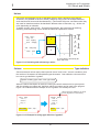
1.3 Operators
Column
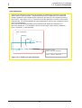
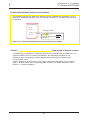
Implicit type conversion
When performing arithmetic or logic operation on different types of data, NC30 converts the
data types following the rules shown below. This is called "implicit type conversion".
• Data types are adjusted to the data type whose bit length is greater than the other before
performing operation.
• When substituting, data types are adjusted to the data type located on the left side of the
equation.
word = byte ;
/∗ int ← char ∗/
When ...
char
int
byte = 0x12 ;
word = 0x3456 ;
0x
0x
00
12
12
0x00 is extended
Figure 1.3.1 Assign different types of data
19
byte = word ;
/∗ char ← int ∗/
0x
34
0x
Upper 1 byte is cut
56
56
Introduction to C Language
1
1.3 Operators
1.3.3 Operators for Processing Data
The operators frequently used to process data are "bitwise operators" and "shift operators".
This section explains these bitwise and shift operators.
Bitwise operators
Use of bitwise operators makes it possible to mask data and perform active conversion.
Table 1.3.5 Bitwise Operators
Operator
Description format
Content
&
expression 1 & expression 2
Returns the logical product of the values of
expressions 1 and 2 after ANDing each bit.
|
expression 1 | expression 2
Returns the logical sum of the values of
expressions 1 and 2 after ORing each bit.
^
expression 1 ^ expression 2
Returns the exclusive logical sum of the values
of expressions 1 and 2 after XORing each bit.
˜
˜expression
Returns the value of the expression after
inverting its bits.
Shift Operators
In addition to shift operation, shift operators can be used in simple multiply and divide
operations. (For details, refer to Column, "Multiply and divide operations using shift
operators".)
Table 1.3.6 Shift Operators
Operator
Description format
<<
expression 1 << expression 2
Shifts the value of expression 1 left by the
amount equal to the value of expression 2,
and returns the result.
expression 1 >> expression 2
Shifts the value of expression 1 right by the
amount equal to the value of expression 2,
and returns the result.
>>
Content
20
Introduction to C Language
1
1.3 Operators
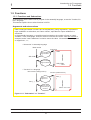
Comparison between arithmetic and logical shifts
When executing "shift right", note that the shift operation varies depending on whether the
data to be operated on is singed or unsigned.
• When unsigned → Logical shift: A logic 0 is inserted into the most significant bit.
• When signed → Arithmetic shift: Shift operation is performed so as to retain the sign.
Namely, if the data is a positive number, a logic 0 is inserted into the
most significant bit; if a negative number, a logic 1 is inserted into the
most significant bit.
<Unsigned>
<Negative number>
<Positive number>
signed int i = 0xFC18
(i = -1000)
signed int i = 0x03E8
(i = +1000)
1111 1100 0001 1000
1111 1100 0001 1000
0000 0011 1110 1000
i >> 1
0111 1110 0000 1100
1111 1110 0000 1100
(-500)
0000 0001 1111 0100
(+500)
i >> 2
0011 1111 0000 0110
1111
1111 1111
1111 0000
0000 0110
0110
(-250)
0000 0000 1111 1010
(+250)
i >> 3
0001 1111 1000 0011
1111 1111 1000 0011
(-125)
0000 0000 0111 1101
(+125)
unsigned int i = 0xFC18
(i = 64520)
Logical shift
Arithmetic shift
(positive or negative sign is retained)
Figure 1.3.2 Arithmetic and logical shifts
21
Introduction to C Language
1
1.3 Operators
Column
Multiply and divide operations using shift operators
Shift operators can be used to perform simple multiply and divide operations. In this case,
operations are performed faster than when using ordinary multiply or divide operators.
Considering this advantage, NC30 generates shift instructions, instead of multiply
instructions, for such operations as "∗2", "∗4", and "∗8".
• Multiplication: Shift operation is performed in combination with add operation.
a∗2→ a<<1
a∗3→ (a<<1) +a
a∗4→ a<<2
a∗7→ (a<<2)+(a<<1) +a
a∗8→ a<<3
a∗20→ (a<<4) + (a<<2)
• Division: The data pushed out of the least significant bit makes it possible to know the
remainder.
a/4→
a>>2
a/8→
a>>3
a/16→ a>>4
22
Introduction to C Language
1
1.3 Operators
1.3.4 Operators for Examining Condition
Used to examine a condition in a control statement are "relational operators" and "logical
operators". Either operator returns a logic 1 when a condition is met and a logic 0 when a
condition is not met.
This section explains these relational and logical operators.
Relational operators
These operators examine two expressions to see which is larger or smaller than the other.
If the result is true, they return a logic 1; if false, they return a logic 0.
Table 1.3.7 Relational Operators
Operator
Description format
Content
True if the value of expression 1 is smaller than
<
expression 1 < expression 2
<=
expression 1 <= expression 2
>
expression 1 > expression 2
True if the value of expression 1 is larger than that
of expression 2; otherwise, false.
>=
expression 1 >= expression 2
True if the value of expression 1 is larger than or
equal to that of expression 2; otherwise, false.
==
expression 1 == expression 2
True if the value of expression 1 is equal to that of
expression 2; otherwise, false.
!=
expression 1 != expression 2
True if the value of expression 1 is not equal to
that of expression 2; otherwise, false.
that of expression 2; otherwise, false.
True if the value of expression 1 is smaller than or
equal to that of expression 2; otherwise, false.
Logical operators
These operators are used along with relational operators to examine the combinatorial
condition of multiple condition expressions.
Table 1.3.8 Logical Operators
Operator
Description format
Content
&&
expression 1 && expression 2
True if both expressions 1 and 2 are true;
otherwise, false.
||
expression 1 || expression 2
False if both expressions 1 and 2 are false;
otherwise, true.
!
! expression
False if the expression is true, or true if the
expression is false.
23
Introduction to C Language
1
1.3 Operators
1.3.5 Other Operators
This section explains four types of operators which are unique in the C language.
Conditional operator
This operator executes expression 1 if a condition expression is true or expression 2 if the
condition expression is false. If this operator is used when the condition expression and
expressions 1 and 2 both are short in processing description, coding of conditional
branches can be simplified. Table 1.3.9 lists this conditional operator. Figure 1.3.3 shows
an example for using this operator.
Table 1.3.9 Conditional Operator
Operator
Description format
? :
Condition expression ?
expression 1 :
expression 2
Content
Executes expression 1 if the condition expression
is true or expression 2 if the condition expression
is false.
• Value whichever larger is selected.
if (a > b){
c=a;
}
else{
c=b;
}
c=a>b?a:b;
• Absolute value is found.
if(a > 0){
c=a;
}
else{
c=-a;
}
c=a>0?a:-a;
Figure 1.3.3 Example for using conditional operator
sizeof operator
Use this operator when it is necessary to know the number of memory bytes used by a
given data type or expression.
Table 1.3.10 sizeof Operator
Operator
sizeof()
Description format
sizeof expression
sizeof (data type)
Content
Returns the amount of memory used by the
expression or data type in units of bytes.
24
Introduction to C Language
1
1.3 Operators
Cast operator
When operation is performed on data whose types differ from each other, the data used in
that operation are implicitly converted into the data type that is largest in the expression.
However, since this could cause an unexpected fault, a cast operator is used to perform
type conversions explicitly.
Table 1.3.11 Cast Operator
Operator
()
Description format
Content
Converts the data type of the variable to
the new data type.
(new data type) variable
Comma operator
This operator executes expression 1 and expression 2 sequentially from left to right. This
operator, therefore, is used when enumerating processing of short descriptions.
Table 1.3.12 Comma operator
Operator
,
Description format
expression 1, expression 2
Content
Executes expression 1 and expression 2
sequentially from left to right.
25
Introduction to C Language
1
1.3 Operators
1.3.6 Priorities of Operators
The operators used in the C language are subject to "priority resolution" and "rules of
combination" as are the operators used in mathematics.
This section explains priorities of the operators and the rules of combination they must follow:
Priority resolution and rules of combination
When multiple operators are included in one expression, operation is always performed in
order of operator priorities beginning with the highest priority operator. When multiple
operators of the same priority exist, the rules of combination specify which operator, left or
right, be executed first.
Table 1.3.13 Operator Priorities
Type of operator
High
Expression
Monadic arithmetic operators, etc.
()
[]
(Note 1)
.
→
->
! ˜
++ – –
sizeof( ) (type)
(Note 4)
combination
–
(Note 2)
∗ &
(Note 3)
←
→
Multiply/divide operators
∗
/
Add/subtract operators
+
–
Shift operator
<<
Relational operator (comparison)
<
<=
Relational operator (equivalent)
==
!=
Bitwise operator (AND)
&
→
Bitwise operator (EOR)
^
→
Bitwise operator (OR)
|
→
&&
→
Logical operator (OR)
||
→
Conditional operator
?:
←
Assignment operator
=
+= –=
∗=
<<= >>= &= ^=
Logical operator (AND)
Low
Rules of
Operator
Comma operator
%
→
→
>>
>
→
>=
→
/=
|=
,
Note 1: The dot '·' denotes a member operator that specifies struct and union members.
Note 2: The asterisk '∗' denotes a pointer operator that indicates a pointer variable.
Note 3: The ampersand '&' denotes an address operator that indicates the address of a variable.
Note 4: The asterisk '∗' denotes a multiply operator that indicates multiplication.
26
%=
←
→
Introduction to C Language
1
1.4 Control Statements
1.4 Control Statements
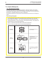
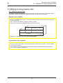
1.4.1 Structuring of Program
The C language allows all of "sequential processing", "branch processing", and "repeat
processing"--the basics of structured programming--to be written using control statements.
Consequently, all programs written in the C language are structured. This is why the flow of
processing in C language programs are easy to understand.
This section describes how to write these control statements and shows some examples of
usage.
Structuring of program
The most important point in making a program easy to understand is how the program flow
can be made easily readable. This requires preventing the program flow from being
directed freely as one wishes. Thus, a move arose to limit it to the three primary forms:
"sequential processing", "branch processing", and "repeat processing". The result is the
technique known as "structured programming".
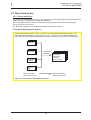
Table 1.4.1 shows the three basic forms of structured programming.
Table 1.4.1 The three basic forms of structured programming
Processing A
Executed top down, from
top to bottom.
Sequential
processing
Processing B
Condition P
False
True
Branch
processing
Processing A
Processing B
Branched to processing A
or processing B
depending on whether
condition P is true or
false.
False
Condition P
True
Repeat
processing
Processing A
27
Processing A is repeated
as long as condition P is
met.
Introduction to C Language
1
1.4 Control Statements
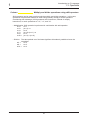
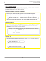
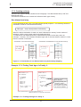
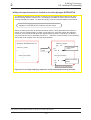
1.4.2 Branching Processing Depending on Condition (branch processing)
Control statements used to write branch processing include "if-else", "else-if", and "switch-case"
statements.
This section explains how to write these control statements and shows some examples of usage.
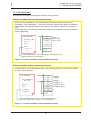
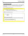
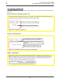
if-else statement
This statement executes the next block if the given condition is true or the "else" block if the
condition is false. Specification of an "else" block can be omitted.
• If the else statement is omitted
Is condition
expression
true?
False
if (condition
expression)
{
Execution statement A
True
Execution
statement A
}
False
if (condition
expression)
Execution
statement A
{
Execution statement A
True
else{
Execution
statement B
Is condition
expression
true?
}
Execution statement B
}
Figure 1.4.1 Example for if-else statement
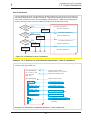
Example 1.4.1 Count Up (if-else statement)
In this example, the program counts up a seconds counter "second" and a minutes counter
"minute". When this program module is called up every 1 second, it functions as a clock.
void count_up(void) ;
Declares "count_up" function. (Refer to Section 1.5,
"Functions".)
unsigned int second = 0 ;
unsigned int minute = 0 ;
Declares variables for "second" (seconds counter)
and "minute" (m inutes counter).
void count_up(void)
{
if(second >= 59 ){
second = 0 ;
minute ++ ;
}
else{
second ++ ;
}
}
Defines "count_up" function.
If greater than 59 seconds,
the module resets "second" and
counts up "minute".
If less than 59 seconds,
the module counts up "second".
Example 1.4.1 Count up (if-else statement)
28
Introduction to C Language
1
1.4 Control Statements
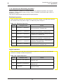
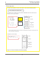
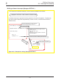
else-if statement
Use this statement when it is necessary to divide program flow into three or more flows of
processing depending on multiple conditions. Write the processing that must be executed
when each condition is true in the immediately following block. Write the processing that
must be executed when none of conditions holds true in the last "else" block.
Is condition
expression 1
true?
True
if (condition expression 1)
Execution
statement A
False
Is condition
expression 2
true?
Is condition
expression 3
true?
False
}
if (condition expression 2)
{
Execution statement B
Execution
statement B
False
Execution statement A
else
True
{
}
else
True
if (condition expression 3)
{
Execution statement C
Execution
statement C
}
else{
Execution
statement D
Execution statement D
}
Figure 1.4.2 Example for else-if statement
Example 1.4.2 Switchover of Arithmetic Operations-1 (else-if statement)
In this example, the program switches over the operation to be executed depending on the
content of the input data "sw".
void select(void);
Declares "select" function.
(Refer to Section 1.5, "Functions".)
int a = 29 , b = 40 ;
long int ans ;
char sw ;
Declares the variables used.
void select(void)
{
if(sw == 0){
ans = a + b ;
}
else if(sw == 1){
ans = a - b ;
}
else if(sw == 2){
ans = a∗b ;
}
else if(sw == 3){
ans = a / b ;
}
else{
error();
}
}
Defines "select" function.
If the content of "sw" is 0,
the program adds data.
If the content of "sw" is 1,
the program subtracts data.
If the content of "sw" is 2,
the program multiplies data.
If the content of "sw" is 3,
the program divides data.
If the content of "sw" is 4 or greater,
the program performs error
processing.
Example 1.4.2 Switchover of arithmetic operations -1 (else-if statement)
29
Introduction to C Language
1
1.4 Control Statements
switch-case statement
This statement causes program flow to branch to one of multiple processing depending on
the result of a given expression. Since the result of an expression is handled as a constant
when making decision, no relational operators, etc. can be used in this statement.
Determination
of expression
Constant 1
Constant 2
switch(expression){
Constant 3
Others
case constant 1: execution statement A
Execution
statement A
break;
case constant 2: execution statement B
Execution
statement B
break;
case constant 3: execution statement C
Execution
statement C
break;
default:
Execution
statement D
execution statement D
break;
}
Figure 1.4.3 Example for switch-case statement
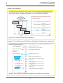
Example 1.4.3 Switchover of Arithmetic Operations-2 (switch-case statement)
In this example, the program switches over the operation to be executed depending on the
content of the input data "sw".
void select(void);
Declares "select" function.
(Refer to Section 1.5, "Functions".)
int a = 29 , b = 40 ;
long int ans ;
char sw ;
Declares the variables used.
void select(void)
{
switch(sw){
Defines "select" function.
case 0 : ans = a + b ;
break ;
case 1 : ans = a - b ;
break ;
case 2 : ans = a∗b ;
break ;
case 3 : ans = a / b ;
break ;
default : error();
break ;
Determines the content of "sw".
If the content of "sw" is 0, the program
adds data.
If the content of "sw" is 1, the program
subtracts data.
If the content of "sw" is 2, the program
multiplies data.
If the content of "sw" is 3, the program
divides data.
If the content of "sw" is 4 or greater, the
program performs error processing.
}
}
Example 1.4.3 Switchover of arithmetic operations -2 (switch-case statement)
30
Introduction to C Language
1
1.4 Control Statements
Column
Switch-case statement without break
A switch-case statement normally has a break statement entered at the end of each of its
execution statements.
If a block that is not accompanied by a break statement is encountered, the program
executes the next block after terminating that block. In this way, blocks are executed
sequentially from above. Therefore, this allows the start position of processing to be
changed depending on the value of an expression.
Determination
of expression
Others Constant 3
switch(expression){
Constant 2 Constant 1
Execution
statement A
case constant 1: execution statement A
Execution
statement B
case constant 2: execution statement B
case constant 3: execution statement C
Execution
statement C
default:
Execution
statement D
}
Figure 1.4.4 switch-case statement without break
31
execution statement D
Introduction to C Language
1
1.4 Control Statements
1.4.3 Repetition of Same Processing (repeat processing)
Control statements used to write repeat processing include "while", "for", and "do-while"
statements.
This section explains how to write these control statements and shows some examples of usage.
while statement
This statement executes processing in a block repeatedly as long as the given condition
expression is met. An endless loop can be implemented by writing a constant other than 0
in the condition expression, because the condition expression in this case is always "true".
Is condition
expression
true?
False
while
(condition expression)
True
{
Execution statement A
Execution
statement A
}
Figure 1.4.5 Example for while statement
Example 1.4.4 Finding Sum Total -1 (while statement)
In this example, the program finds the sum of integers from 1 to 100.
void sum(void) ;
Declares "sum" function. (Refer to Section 1.5,
"Functions".)
unsigned int total = 0 ;
Declares the variables used.
void sum(void)
{
unsigned int i = 1 ;
Defines "sum" function.
while(i <= 100){
total += i ;
i ++ ;
}
Defines and initializes counter variables.
Loops until the counter content reaches 100.
Changes the counter content.
}
Example 1.4.4 Finding sum total -1 (while statement)
32
Introduction to C Language
1
1.4 Control Statements
for statement
The repeat processing that is performed by using a counter like in Example 1.4.4 always
requires operations to "initialize" and "change" the counter content, in addition to
determining the given condition. A for statement makes it possible to write these
operations along with a condition expression. (See Figure 1.4.6.) Initialization (expression
1), condition expression (expression 2), and processing (expression 3) each can be
omitted. However, when any of these expressions is omitted, make sure the semicolons (;)
placed between expressions are left in. This for statement and the while statement
described above can always be rewritten.
Expression 1
for (expression 1; expression 2; expression 3){
Is expression 2
true?
False
True
Execution statement
Execution
statement
}
Expression 3
Figure 1.4.6 Example for "for" statement
Example 1.4.5 Finding Sum Total -2 (for statement)
In this example, the program finds the sum of integers from 1 to 100.
void sum(void) ;
Declares "sum" function.
(Refer to Section 1.5, "Functions".)
unsigned int total = 0 ;
Declares the variables used.
void sum(void)
{
unsigned int i ;
Defines "sum" function.
Defines counter variables.
Loops until the counter content
increments from 1 to 100.
for(i = 1 ; i <= 100 ; i++){
total += i ;
}
}
Example 1.4.5 Finding sum total -2 (for statement)
33
Introduction to C Language
1
1.4 Control Statements
do-while statement
Unlike the for and while statements, this statement determines whether a condition is true
or false after executing processing (post-execution determination). Although there could be
some processing in the for or while statements that is never once executed, all processing
in a do-while statement is executed at least once.
Execution
statement A
True Is condition
expression
true?
do{
Execution statement
} while (condition expression);
False
Figure 1.4.7 Example for do-while statement
Example 1.4.6 Finding Sum Total -3 (do-while statement)
In this example, the program finds the sum of integers from 1 to 100.
void sum(void) ;
Declares "sum" function. (Refer to
Section 1.5, "Functions".)
unsigned int total = 0 ;
Declares the variables used.
void sum(void)
{
unsigned int i = 0 ;
Defines "sum" function.
do{
i ++ ;
total += i ;
}while(i < 100) ;
Defines and initializes counter variables.
Loops until the counter content increments from 1 to 100.
}
Example 1.4.6 Finding sum total -3 (do-while statement)
34
Introduction to C Language
1
1.4 Control Statements
1.4.4 Suspending Processing
There are control statements (auxiliary control statements) such as break, continue, and goto
statements that make it possible to suspend processing and quit.
This section explains how to write these control statements and shows some examples of usage.
break statement
Use this statement in repeat processing or in a switch-case statement. When "break;" is
executed, the program suspends processing and exits only one block.
• When used in a for statement
• When used in a while statement
Expression 1
Is condition
expression
true?
False
Is expression 2
true?
False
True
True
Execution statement
Execution statement
----break;
-----
--------break;
-----
Expression 3
Figure 1.4.8 Example for break statement
continue statement
Use this statement in repeat processing. When "continue;" is executed, the program
suspends processing. After being suspended, the program returns to condition
determination when continue is used in a while statement or executes expression 3 before
returning to condition determination when used in a for statement.
• When used in a for statement
• When used in a while statement
Expression 1
Is condition
expression
true?
False
Is expression 2
true?
True
True
Execution statement
Execution statement
----------continue;
------
-----continue;
-----Expression 3
Figure 1.4.9 Example for continue statement
35
False
Introduction to C Language
1
1.4 Control Statements
goto statement
When a goto statement is executed, the program unconditionally branches to the label
written after the goto statement. Unlike break and continue statements, this statement
makes it possible to exit multiple blocks collectively and branch to any desired location in
the function. (See Figure 1.4.10.) However, since this operation is contrary to structured
programming, it is recommended that a goto statement be used in only exceptional cases
as in error processing.
Note also that the label indicating a jump address must always be followed by an
execution statement. If no operation need to be performed, write a dummy statement
(only a semicolon ';') after the label.
void main(void)
{
while(1){
····
while(···){
if(···){
goto err;
}
}
}
err: errorf();
Entering a label
label: execution statement;
}
If no operation need to be performed,
label: ; (dummy statement)
Figure 1.4.10 Working of goto statement
36
Introduction to C Language
1
1.5 Functions
1.5 Functions
1.5.1 Functions and Subroutines
As subroutines are the basic units of program in the assembly language, so are the "functions" in
the C language.
This section explains how to write functions in NC30.
Arguments and return values
Data exchanges between functions are accomplished by using "arguments", equivalent to
input variables in a subroutine, and "return values", equivalent to output variables in a
subroutine.
In the assembly language, no restrictions are imposed on the number of input or output
variables. In the C language, however, there is a rule that one return value per function is
accepted, and a "return statement" is used to return the value. No restrictions are imposed
on arguments. (Note)
• "Subroutine" in assembly language
Main routine
Subroutine
Input variable 1
Input variable 2
••
•
SUB:
JSR SUB
Output variable 1
Output variable 2
••
•
SUB_END:
RTS
• "Function" in C language
Main function (calling function)
Argument 1
Argument 2
Function (called function)
func(···)
{
func(···) ;
Return value
(One value per
function)
return
return value;
}
Figure 1.5.1 "Subroutine" vs. "function"
Note: In some compilers designed for writing a finished program into ROM, the number of arguments is limited.
37
Introduction to C Language
1
1.5 Functions
1.5.2 Creating Functions
Three procedures are required before a function can be used. These are "function declaration"
(prototype declaration), "function definition", and "function call".
This section explains how to write these procedures.
Function declaration (prototype declaration)
Before a function can be used in the C language, function declaration (prototype
declaration) must be entered first. The type of function refers to the data types of the
arguments and the returned value of a function.
The following shows the format of function declaration (prototype declaration):
data type of returned value
function name (list of data types of arguments)
If there is no returned value and argument, write the type called "void" that means null.
Function definition
In the function proper, define the data types and the names of "dummy arguments" that are
required for receiving arguments. Use the "return statement'' to return the value for the
argument.
The following shows the format of function definition:
data type of return value function name (data type of dummy argument 1 dummy
{
argument 1, ...)
•
•
•
return return value;
}
Function call
When calling a function, write the argument for that function. Use a assignment operator to
receive a return value from the called function.
function name (argument 1, ...);
When there is a return value
variable = function name (argument 1, ...);
38
Introduction to C Language
1
1.5 Functions
Example for a function
In this example, we will write three functions that are interrelated as shown below.
No argument
int type
No return value
Main function
int type
char type
main
int type
No return value
Function 1
Function 2
func 1
func 2
/∗ Prototype declaration
void main ( void ) ;
int func1 ( int ) ;
void func2 ( int , char ) ;
∗/
/∗ Main function ∗/
void main()
{
int a = 40 , b = 29 ;
int ans ;
char c = 0xFF ;
Calls function 1 ("func1") using a as argument.
Return value is substituted for "ans".
ans = func1 ( a ) ;
func2 ( b , c ) ;
}
/∗ Definition function 1
int func1 ( int x )
{
int z ;
Calls function 2 ("func2") using b, c as arguments.
There is no return value.
∗/
••
•
return z ;
}
/∗ Definition function 2 ∗/
void func2 ( int y , char m )
{
}
Returns a value for the argument
using a "return statement".
••
•
Figure 1.5.2 Example for a function
39
Introduction to C Language
1
1.5 Functions
1.5.3 Exchanging Data between Functions
In the C language, exchanges of arguments and return values between functions are
accomplished by copying the value of each variable as it is passed to the receiver ("Call by
Value"). Consequently, the name of the argument used when calling a function and the name of
the argument (dummy argument) received by the called function do not need to coincide.
Since processing in the called function is performed using copied dummy arguments, there is no
possibility of damaging the argument proper in the calling function.
For these reasons, functions in the C language are independent of each other, making it possible
to reuse the functions easily.
This section explains how data are exchanged between functions.
Example 1.5.1 Finding Sum of Integers (example for a function)
In this example, using two arbitrary integers in the range of -32,768 to 32,767 as
arguments, we will create a function "add" to find a sum of those integers and call it from
the main function.
/∗ Prototype declaration
void main ( void ) ;
long add ( int , int ) ;
∗/
/∗ Main function ∗/
void main ( void )
{
long int answer ;
int a = 29 , b = 40 ;
answer = add ( a , b ) ;
(1) Calls the add function.
}
/∗ Add function ∗/
long add ( int x , int y )
{
long int z ;
(2) Executes addition.
z = ( long int ) x + y ;
return z ;
(3) Returns a value
for the argument.
}
<Flow of data>
Main function
a
b
29
40
answer
(1) copy
Add function
dummy
dummy
x argument + y argument
Example 1.5.1 Finding sum of integers (a function)
40
(3) copy
(2)
z
Introduction to C Language
1
1.6 Storage Classes
1.6 Storage Classes
1.6.1 Effective Range of Variables and Functions
Variables and functions have different effective ranges depending on their nature, e.g., whether
they are used in the entire program or in only one function. These effective ranges of variables
and functions are called "storage classes (or scope)".
This section explains the types of storage classes of variables and functions and how to specify
them.
Effective range of variables and functions
A C language program consists of multiple source files. Furthermore, each of these source
files consists of multiple functions. Therefore, a C language program is hierarchically
structured as shown in Figure 1.6.1.
There are following three storage classes for a variable:
(1) Effective in only a function
(2) Effective in only a file
(3) Effective in the entire program
There are following two storage classes for a function:
(1) Effective in only a file
(2) Effective in the entire program
In the C language, these storage classes can be specified for each variable and each
function. Effective utilization of these storage classes makes it possible to protect the
variables or functions that have been created or conversely share them among the
members of a team.
(3)
Storage classes of variable
Storage classes of function (2)
Program
(2)
(1)
Effective
range
File
File
Effective
range
(1)
Function Function
Function Function
Function Function
Figure 1.6.1 Hierarchical structure and storage classes of C language program
41
Introduction to C Language
1
1.6 Storage Classes
1.6.2 Storage Classes of Variables
The storage class of a variable is specified when writing type declaration. There are following two
points in this:
(1) External and internal variables (→ location where type declaration is entered)
(2) Storage class specifier (→ specifier is added to type declaration)
This section explains how to specify storage classes for variables.
External and internal variables
This is the simplest method to specify the effective range of a variable. The variable
effective range is determined by a location where its type declaration is entered. Variables
declared outside a function are called "external variables" and those declared inside a
function are called "internal variables". External variables are global variables that can be
referenced from any function following the declaration. Conversely, internal variables are
local variables that can be effective in only the function where they are declared following
the declaration.
int main(void) ;
int func(void) ;
External to function
int tmp ;
Effective range
of tmp
int main(void)
{
int a ;
Internal to function
Effective range of a
}
External to function
int func(void)
{
int b ;
Internal to function
Effective range of b
}
Figure 1.6.2 External and internal variables
Storage class specifiers
The storage class specifiers that can be used for variables are auto, static, register, and
extern. These storage class specifiers function differently when they are used for external
variables or internal variables. The following shows the format of a storage class specifier.
storage class specifier ∆ data type ∆ variable name;
42
Introduction to C Language
1
1.6 Storage Classes
Storage classes of external variable
If no storage class specifier is added for an external variable when declaring it, the variable
is assumed to be a global variable that is effective in the entire program. On the other
hand, if an external variable is specified of its storage class by writing "static" when
declaring it, the variable is assumed to be a local variable that is effective in only the file
where it is declared.
Write the specifier "extern" when using an external variable that is defined in another file
like "mode" in source file 2 of Figure 1.6.3.
Source file 1
Memory space
Source file 2
char mode ;
static int count ;
extern char mode ;
static int count ;
void func1(void)
{
mode = STOP ;
count = 0 ;
void func2(void)
{
mode = BACK ;
count = 100 ;
••
•
••
•
Program
area
Common mode
count of source
file 1
Data area
••
•
count of source
file 2
Stack area
••
•
Figure 1.6.3 Storage classes of external variable
Storage classes of internal variable
An internal variable declared without adding any storage class specifier has its area
allocated in a stack. Therefore, such a variable is initialized each time the function is
called. On the other hand, an internal variable whose storage class is specified to be
"static" is allocated in a data area. In this case, therefore, the variable is initialized only
once when starting up the program.
Source file
void func1(void)
{
char flag = 0 ;
static int count = 0 ;
••
•
flag = SET ;
count = count + 1 ;
func2() ;
Memory space
Program
area
count of func1
count of func2
Data area
••
•
••
•
}
void func2(void)
{
char flag = 0 ;
static int count = 0 ;
••
•
Stack area
••
•
flag of func2
••
•
Return
address
flag = SET ;
count = count + 1 ;
••
•
}
flag of func1
••
•
••
•
Figure 1.6.4 Storage classes of internal variable
43
Introduction to C Language
1
1.6 Storage Classes
1.6.3 Storage Classes of Functions
The storage class of a function is specified on both function defining and function calling sides.
The storage class specifiers that can be used here are static and extern.
This section explains how to specify the storage class of a function.
Global and local functions
(1) If no storage class is specified for a function when defining it
This function is assumed to be a global function that can be called and used from any
other source file.
(2) If a function is declared to be "static" when defining it
This function is assumed to be a local function that cannot be called from any other
source file.
(3) If a function is declared to be "extern" in its type declaration
This storage class specifier indicates that the declared function is not included in the
source file where functions are declared, and that the function in some other source file
be called. However, only if a function has its type declared--even though it may not be
specified to be "extern", if the function is not found in the source file, the function in
some other source file is automatically called in the same way as when explicitly
specified to be "extern".
Source file 2
Source file 1
void func1(void)
{
···
}
void func1(void) ;
extern void func2(void) ;
void func3(void) ;
Can be called
void main(void)
{
func1() ;
func2() ;
func3() ;
}
void func2(void)
{
···
}
Can be called
Can be called
static void func3(void)
{
···
}
Figure 1.6.5 Storage classes of function
44
Introduction to C Language
1
1.6 Storage Classes
Summary of storage classes
Storage classes of variables are summarized in Table 1.6.1. Storage classes of functions
are summarized in Table 1.6.2.
Table 1.6.1 Storage Classes of Variables
Storage
class
Storage
class
specifiers
omitted
External variable
Internal variable
Global variables that can also be
referenced from other source files.
[Allocated in a data area]
Variables that are effective in only the
function [Allocated in a stack when
executing the function]
auto
static
Local variables that cannot be
referenced from other source files
[Allocated in a data area]
Variables that are effective in only the
function [Allocated in a data area]
Variables that are effective in only the
function [Allocated in a register when
executing the function]
However, they do not have any effect
in NC30 (ignored when compiled).
register
extern
Variables that are effective in only the
function [Allocated in a stack when
executing the function]
Variables that reference variables in
other source files
[Not allocated in memory]
Variables that reference variables in
other source files (cannot be
referenced from other functions)
[Not allocated in memory]
Table 1.6.2 Storage Classes of Functions
Storage class
Storage class
specifiers
omitted
Types of functions
Global functions that can be called and executed from other source files
[Specified on function defining side]
static
Local functions that can not be called and executed from other source files
[Specified on function defining side]
extern
Calls a function in other source files [Specified on function calling side]
45
Introduction to C Language
1
1.7 Arrays and Pointers
1.7 Arrays and Pointers
1.7.1 Arrays
Arrays and pointers are the characteristic features of the C language.
This section describes how to use arrays and explains pointers that provide an important means
of handling the array.
What is an array?
The following explains the functionality of an array by using a program to find the total age
of family members as an example. The family consists of parents (father = 29 years old,
mother = 24 years old), and a child (boy = 4 years old). (See Example 1.7.1.)
In this program, the number of variable names increases as the family grows. To cope with
this problem, the C language uses a concept called an "array". An array is such that data
of the same type (int type) are handled as one set. In this example, father's age (father),
mother's age (mother), and child's age (boy) all are not handled as separate variables, but
are handled as an aggregate as family age (age). Each data constitutes an "element" of
the aggregate. Namely, the 0'th element is father, the 1st element is mother, and the 2nd
element is the boy.
Multiple
variables of the
same data type
father
29
mother
24
Array
age
boy
29
24
4
0'th element (= papa)
1st element (= mama)
4
Figure 1.7.1 Concept of an array
Example 1.7.1 Finding Total Age of a Family -1
In this example, we will find the total age of family members (father, mother, and boy).
As the family grows, so do the type declaration of
variables and the execution statements to be initialized.
void main(void)
{
int father = 29 ;
int mother = 24 ;
int boy = 4 ;
int total ;
total = father + mother + boy ;
}
void main(void)
{
int father = 29 ;
int mother = 24 ;
int boy = 4 ;
int sister 1 = 1 ;
int sister 2 = 1 ;
int total ;
total = father + mother + boy + sister 1 + sister 2 + ···;
}
Example 1.7.1 Finding total age of a family -1
46
Introduction to C Language
1
1.7 Arrays and Pointers
1.7.2 Creating an Array
There are two types of arrays handled in the C language: "one-dimensional array" and "twodimensional array".
This section describes how to create and reference each type of array.
One-dimensional array
A one-dimensional array has a one-dimensional (linear) expanse. The following shows the
declaration format of a one-dimensional array.
Data type
array name [number of elements];
When the above declaration is made, an area is allocated in memory for the number of
elements, with the array name used as the beginning label.
To reference a one-dimensional array, add element numbers to the array name as
subscript. However, since element numbers begin with 0, the last element number is 1 less
than the number of elements.
• Declaration of one-dimensional array
• Declaration and initialization of one-dimensional array
8 bits
8 bits
buff 1→
char buff1[3] ;
int buff2[3] ;
buff1[0]
buff 1→
char buff1[ ] = {
'a' , 'b' , 'c'
};
buff1[1]
buff1[2]
buff 2→
buff2[0]
int buff2[ ] = {
10 , 20 , 30
};
buff2[1]
buff2[2]
'a'
'b'
'c'
buff 2→
10
20
30
Figure 1.7.2 Declaration of one-dimensional array and memory mapping
Example 1.7.2 Finding Total Age of a Family -2
In this example, we will find the total age of family members by using an array.
#define MAX 3 (Note)
#define MAX 3
void main(void)
{
int age[MAX] ;
int total = 0 ;
int i ;
void main(void)
{
int age[ ] = {
29 , 24 , 4
};
or
age[0] = 29 ;
age[1] = 24 ;
age[2] = 4 ;
for(i = 0 ; i < MAX ; i++) {
total += age[i] ;
}
int total = 0 ;
int i ;
for(i = 0 ; i < MAX ; i++) {
total += age[i] ;
}
}
(Note): #define MAX 3: Synonym defined as MAX = 3.
(Refer to Section 1.9, Preprocess Commands".)
Example 1.7.2 Finding total age of a family -2
47
Initialized simultaneously
when declared.
By using an array, it is
possible to utilize a
repeat statement where
the number of elements
are used as variables.
Introduction to C Language
1
1.7 Arrays and Pointers
Two-dimensional array
A two-dimensional array has a planar expanse comprised of "columns" and "rows". Or it
can be considered to be an array of one-dimensional arrays. The following shows the
declaration format of a two-dimensional array.
Data type
array name [number of rows] [number of columns];
To reference a two-dimensional array, add "row numbers" and "column numbers" to the
array name as subscript. Since both row and column numbers begin with 0, the last row
(or column) number is 1 less than the number of rows (or columns).
• Concept of two-dimensional array
Columns→
Rows Row 0
Row 0
Row 0
Row 0
↓
column 0 column 1 column 2 column 3
Row 1
Row 1
Row 1
Row 1
column 0 column 1 column 2 column 3
Row 2
Row 2
Row 2
Row 2
column 0 column 1 column 2 column 3
• Declaration and initialization of twodimensional array
char buff 1[2][3] ;
• Declaration and initialization of two-dimensional array
buff 1[0]→ buff 1[0][0]
char buff 1[2][3] = {
{ 'a' , 'b' , 'c' } ,
{ 'd' , 'e' , 'f' } ,
};
buff 1[0][1]
buff 1[0][2]
buff 1[1]→
buff 2[0]→
int buff 2[2][3] ;
buff 1[1][0]
buff 1[0]→
'a'
'b'
'c'
buff 1[1]→
'd'
buff 1[1][1]
'e'
buff 1[1][2]
'f'
buff 2[0]→
buff 2[0][0]
buff 2[0][1]
buff 2[0][2]
buff2[1]→
buff 2[1][0]
buff 2[1][1]
10
int buff 2[ ][3] = {
10 , 20 , 30 , 40 , 50 , 60
};
20
When initializing a twodimensional array
simultaneously with
declaration,
specification of the
number of rows can be
omitted. (Number of
columns cannot be
omitted.)
30
buff 2[1]→
buff 2[1][2]
40
50
60
Figure 1.7.3 Declaration of two-dimensional array and memory mapping
48
Introduction to C Language
1
1.7 Arrays and Pointers
1.7.3 Pointers
A pointer is one that points to data; i.e., it indicates an address.
A "pointer variable" which will be described here handles the "address" at which data is stored as
a variable. This is equivalent to one that is referred to as "indirect addressing" in the assembly
language.
This section explains how to declare and reference a pointer variable.
Declaring a pointer variable
The format show below is used to declare a pointer variable.
Pointed data type ∗ pointer variable name;
However, it is only an area to store an address that is allocated in memory by the above
declaration. For the data proper to be assigned an area, it is necessary to write type
declaration separately.
• Pointer variable declaration
char ∗p ;
int ∗p ;
p
Address
∗p
char type
data
char ∗∗p ;
p
Address
∗p
p
Address
∗p
int type
data
∗∗p
No area is allocated.
Figure 1.7.4 Pointer variable declaration and memory mapping
49
Address
char type
data
Introduction to C Language
1
1.7 Arrays and Pointers
Relationship between pointers and variables
The following explains the relationship between pointer variables and variables by using a
method for substituting constant '5' by using pointer variable 'p' for variable of int type 'a' as
an example.
void main(void)
{
int a ;
int ∗p ;
p = &a ;
∗p = 5 ;
}
Address modifier
↓
This "&a" indicates the address of
variable 'a'.
This "∗p" indicates the content of
variable 'a'.
Figure 1.7.5 Relationship between pointer variables and variables
Column
Data length of pointer variable
The data length of variables in C language programs are determined by the data type. For
a pointer variable, since its content is an address, the data length provided for it is
sufficiently large to represent the entire address space that can be accessed by the
microprocessor used.
Pointer variables in NC30 are two or four bytes in data length depending on the location
(near or far area) where the corresponding data is stored. For details about this, refer to
Section 2.1, "Memory Mapping".
50
Introduction to C Language
1
1.7 Arrays and Pointers
1.7.4 Using Pointers
This section shows some examples for effectively using a pointer.
Pointer variables and one-dimensional array
When an array is declared by using subscripts to indicate its element numbers, it is
encoded as "index addressing". In this case, therefore, address calculations to determine
each address "as reckoned from the start address" are required whenever accessing the
array.
On the other hand, if an array is declared by using pointer variables, it can be accessed in
indirect addressing.
void main(void)
{
char str[ ] = "ab" ;
char ∗p ;
char t ;
str
'a'
str[0] or ∗p
'b'
str[1] or ∗(p+1)
'\0'
str[1] or ∗(p+2)
'b'
p = str ;
t = ∗(p + 1) ;
t
p
The start address of a one-dimensional array can be obtained by "str".
(Address modifier '&' is unnecessary.)
Figure 1.7.6 Pointer variables and one-dimensional array
Pointer variables and two-dimensional array
As in the case of a one-dimensional array, a two- dimensional array can also be accessed
by using pointer variables.
void main(void)
{
char mtx[2][3] = {
"ab" , "cd"
};
char ∗p ;
char t ;
mtx[0]
'a'
mtx[1]
'b'
mtx[0][0]
mtx[0][1]
'\0'
mtx[0][2]
'c'
mtx[1][0] or ∗p
'd'
mtx[1][1] or ∗(p+1)
'\0'
mtx[1][2] or ∗(p+2)
'd'
p = mtx[1];
t = ∗(p + 1) ;
t
p
••
•
The start address of the first row of a two-dimensional array
"mtx" can be obtained by "mtx[1]". ('&' is unnecessary.)
Figure 1.7.7 Pointer variables and two-dimensional array
51
Introduction to C Language
1
1.7 Arrays and Pointers
Passing addresses between functions
The basic method of passing data to and from C language functions is referred to as "Call
by Value". With this method, however, arrays and character strings cannot be passed
between functions as arguments or returned values.
Used to solve this problem is a method, known as "Call by Reference", which uses a
pointer variable. In addition to passing the addresses of arrays or character strings
between functions, this method can be used when it is necessary to pass multiple data as a
returned value.
Unlike the Call by Value method, this method has a drawback in that the independency of
each function is reduced, because the data in the calling function is rewritten directly.
Figure 1.7.8 shows an example where an array is passed between functions using the Call
by Reference method.
<Calling function>
#define MAX 5
void cls_str ( char
∗);
main ( void )
Received as pointer variable
∗p
=
void
{
<Called function>
str
str [ 0 ]
str [ 1 ]
char
str [ MAX ] ;
void
{
int
••
•
••
•
i;
••
•
for ( i = 0 ; i < MAX ; i ++ ){
∗( p + i ) = 0 ;
}
cls_str ( str ) ;
••
•
}
cls_str ( char ∗p )
p
}
The array's start
address is passed
as argument.
The array body is
operated on.
Figure 1.7.8 Example of Call by Reference for passing an array
Column
Passing data between functions at high speed
In addition to the Call by Value and the Call by Reference methods, there is another
method to pass data to and from functions. With this method, the data to be passed is
turned into an external variable.
This method results in loosing the independency of functions and, hence, is not
recommended for use in C language programs. Yet, it has the advantage that functions
can be called at high speed because entry and exit processing (argument and return value
transfers) normally required when calling a function are unnecessary. Therefore, this
method is frequently used in ROM'ed programs where general-purpose capability is not an
important requirement and the primary concern is high-speed processing.
52
Introduction to C Language
1
1.7 Arrays and Pointers
1.7.5 Placing Pointers into an Array
This section explains a "pointer array" where pointer variables are arranged in an array.
Pointer array declaration
The following shows how to declare a pointer array.
Data type
far(Note) ∗ array name [number of elements];
• Pointer array declaration
char far ∗ptr1[3] ;
int far ∗ptr2[3] ;
ptr1 →
ptr2 →
ptr1[0]
char type data
ptr1[1]
char type data
ptr1[2]
char type data
ptr2[0]
int type data
ptr2[1]
int type data
ptr2[2]
int type data
• Pointer array initialization
ptbl →
char far ∗ptbl[4] = {
"STOP",
"START",
"RESET",
"RESTART"
};
ptbl[0]
Address of 'S'
'S' 'T'
'O' 'P' '\0'
'S' 'T'
'A' 'R' 'T' '\0'
ptbl[1]
Address of 'S'
ptbl[2]
Address of 'R'
'R' 'E' 'S' 'E' 'T' '\0'
ptbl[3]
Address of 'R'
'R' 'E' 'S' 'T'
'A' 'R' 'T' '\0'
Each character string's start address is stored here.
Figure 1.7.9 Pointer array declaration and initialization
Note: In NC30, the body data of a pointer array is located in the far area. Consequently, be sure to write "far" for the pointer. (For
details, refer to Section 2.3.1, "Efficient Addressing".)
53
Introduction to C Language
1
1.7 Arrays and Pointers
Pointer array and two-dimensional array
The following explains the difference between a pointer array and a two-dimensional array.
When multiple character strings each consisting of a different number of characters are
declared in a two-dimensional array, the free spaces are filled with null code "\0". If the
same is declared in a pointer array, there is no free space in memory. For this reason, a
pointer array is a more effective method than the other type of array when a large amount
of character strings need to be operated on or it is necessary to reduce memory
requirements to a possible minimum.
• Two-dimensional array
char name[ ][7] ={
"Norita" ,
"Rumi" ,
"Ryo-ma"
};
'N'
'o'
'r'
'i'
't'
'R'
'u'
'm'
'i'
'\0'
'R'
'y'
'o'
'-'
'a' '\0'
'\0'
Filled with null code.
'\0'
'm' 'a' '\0'
• Pointer array
name[0]
char far ∗name[3] = {
"Norita" ,
"Rumi" ,
"Ryo-ma"
};
Address of 'N'
'N'
'o'
'r'
'i'
't'
'a' '\0'
name[1]
Address of 'R'
'R'
'u'
'm'
'i'
'\0'
name[2]
Address of 'R'
'R'
'y'
'o'
'-'
'm' 'a' '\0'
Figure 1.7.10 Difference between two-dimensional array and pointer array
54
Introduction to C Language
1
1.7 Arrays and Pointers
1.7.6 Table Jump Using Function Pointer
In assembly language programs, "table jump" is used when switching processing load increases
depending on the contents of some data. The same effect as this can be obtained in C language
programs also by using the pointer array described above.
This section explains how to write a table jump using a "function pointer".
What does a function pointer mean?
A "function pointer" is one that points to the start address of a function in the same way as
the pointer described above. When this pointer is used, a called function can be turned
into a parameter. The following shows the declaration and reference formats for this
pointer.
<Declaration format> Type of return value (∗ function pointer name) (data type of argument);
<Reference format> Variable in which to store return value = (∗ function pointer name) (argument);
55
Introduction to C Language
1
1.7 Arrays and Pointers
Example 1.7.3 Switching Arithmetic Operations Using Table Jump
The method of calculation is switched over depending on the content of variable "num".
/∗ Prototype declaration∗∗∗∗∗∗∗∗∗∗∗∗∗∗/
int calc_f ( int , int , int ) ;
int add_f (int , int ) , sub_f ( int , int ) ;
int mul_f ( int , int ) , div_f ( int , int ) ;
/∗ Jump table ∗∗∗∗∗∗∗∗∗∗∗∗∗∗/
int (∗const jmptbl[ ] ) ( int , int ) = {
add_f , sub_f , mul_f , div_f
};
void
{
Function pointers arranged in an array
main ( void )
int
int
x = 10 , y = 2 ;
num , val ;
num = 2 ;
if ( num < 4 ) {
val = calc_f ( num , x , y ) ;
}
Start address
of "add_f"
jmptbl[1]
Start address
of "sub_f"
jmptbl[2]
Start address
of "mul_f"
jmptbl[3]
}
int
{
jmptbl[0]
calc_f ( int m , int x , int y )
int
int
z;
(∗p ) ( int , int ) ;
p = jmptbl [ m ] ;
z = (∗p ) ( x , y ) ;
return z ;
Setting of jump address
Function call using a function pointer
}
Example 1.7.3 Switching arithmetic operations using table jump
56
Start address
of "div_f"
Introduction to C Language
1
1.8 Struct and Union
1.8 Struct and Union
1.8.1 Struct and Union
The data types discussed hereto (e.g., char, signed int, and unsigned log int types) are called the
"basic data types" stipulated in compiler specifications.
The C language allows the user to create new data types based on these basic data types.
These are "struct" and "union".
The following explains how to declare and reference structs and unions.
From basic data types to structs
Structs and unions allows the user to create more sophisticated data types based on the
basic data types according to the purposes of use. Furthermore, the newly created data
types can be referenced and arranged in an array in the same way as the basic data types.
Names
Addresses
Collectively
managed
Telephone
numbers
Names
Addresses
Telephone
numbers
Dates of birth
Dates of
birth
Basic data types
(elements of struct)
More sophisticated
data types (structs)
Figure 1.8.1 From basic data types to structs
57
Introduction to C Language
1
1.8 Struct and Union
1.8.2 Creating New Data Types
The elements that constitute a new data type are called "members". To create a new data type,
define the members that constitute it. This definition makes it possible to declare a data type to
allocate a memory area and reference it as necessary in the same way as the variables
described earlier.
This section describes how to define and reference structs and unions, respectively.
Difference between struct and union
When allocating a memory area, members are located differently for structs and unions.
(1) Struct: Members are sequentially located.
(2) Union: Members are located in the same address.
(Multiple members share the same memory area.)
Definition and declaration of struct
To define a struct, write "struct".
struct struct tag {
member 1;
member 2;
•
•
•
};
The above description creates a data type "struct struct tag". Declaration of a struct with
this data type allocates a memory area for it in the same way as for an ordinary variable.
struct ∆ struct tag ∆ struct variable name;
58
Introduction to C Language
1
1.8 Struct and Union
Referencing struct
To refer to each member of a struct, use a period '.' that is a struct member operator.
struct variable name.member name
To initialize a struct variable, list each member's initialization data in the order they are
declared, with the types matched.
••
•
struct person{
char ∗name ;
long number ;
char section[5] ;
int work_year ;
};
void main(void)
{
struct person
••
•
name
a
a.number
number
••
•
section[0]
section[1]
section[2]
section[3]
section[4]
b
a,b;
••
•
a.name
••
•
a.section[0]
to
a.section[4]
a.work_year
work_year
••
•
If the area that contains name is a near area, "struct person" becomes a 13-byte type; if a far
area, it becomes a 15-byte type.
∗ Initialization of struct variable
••
•
Address
of 's'
struct person a = {
"SATOH" , 10025 , "T511" , 25
};
10025
'T'
'5'
'1'
'1'
'\0'
25
••
•
Figure 1.8.2 Struct declaration and memory mapping
59
a.name
a.number
a.section[0]
to
a.section[4]
a.work_year
Introduction to C Language
1
1.8 Struct and Union
Example for referencing members using a pointer
To refer to each member of a struct using a pointer, use an arrow '->'.
Pointer -> member name
struct person{
char far ∗name ;
long number ;
char section[5] ;
int work_year ;
};
struct person a = {
"SATOH" , 10025 , "T511" , 25
};
••
•
&a
a or ∗p
10025
p->name
p->number
••
•
p
void main(void)
{
struct person
p = &a ;
Address
of 'S'
••
•
∗p ;
••
•
'T'
'5'
'1'
'1'
'\0'
25
Figure 1.8.3 Example for referencing members using a pointer
60
p->section[0]
to
p->section[4]
p->work_year
Introduction to C Language
1
1.8 Struct and Union
Unions
Unions are characteristic in that an allocated memory area is shared by all members.
Therefore, it is possible to save on memory usage by using unions for multiple entries of
such data that will never exist simultaneously. Unions also will prove convenient when they
are used for data that needs to be handled in different units of data size, e.g., 16 bits or 8
units, depending on situation.
To define a union, write "union". Except this description, the procedures for defining,
declaring, and referencing unions all are the same as explained for structs.
••
•
••
•
union pack {
long all ;
char byte[4] ;
short word[2] ;
};
void main(void)
{
union pack a , b ;
••
•
word
all
[0]
a
[0]
[1]
••
•
[2]
[1]
b
[3]
••
•
••
•
byte
A 4-byte area is shared by all,
byte, and word.
Figure 1.8.4 Declaring and referencing a union
Column
Type definition
Since structs and unions require the keywords "struct" and "union", there is a tendency that
the number of characters in defined data types increases. One method to circumvent this
is to use a type definition "typedef".
typedef existing type name new type name;
When the above description is made, the new type name is assumed to be synonymous
with the existing type name and, therefore, either type name can be used in the program.
Figure 1.8.5 below shows an example of how "typedef" can actually be used.
When using type definition, the struct
(union) tag name is unnecessary.
struct data{
char a ;
short b ;
long c ;
};
struct data
typedef struct {
char a ;
short b ;
long c ;
} DATA ;
sdata , ∗sptr ;
DATA
••
•
sdata , ∗sptr ;
••
•
Figure 1.8.5 Example for using type definition "typedef"
61
Introduction to C Language
1
1.9 Preprocess Commands
1.9 Preprocess Commands
1.9.1 Preprocess Commands of NC30
The C language supports file inclusion, macro function, conditional compile, and some other
functions as "preprocess commands".
The following explains the main preprocess commands available with NC30.
Preprocess command list of NC30
Preprocess commands each consist of a character string that begins with the symbol '#' to
discriminate them from other execution statements. Although they can be written at any
position, the semicolon ';' to separate entries is unnecessary. Table 1.9.1 lists the main
preprocess commands that can be used in NC30.
Table 1.9.1 Main Preprocess Commands of NC30
Description
Function
#include
Takes in a specified file.
#define
Replaces character string and defines macro.
#undef
Cancels definition made by #define.
#if to #elif to #else to #endif
Performs conditional compile.
#ifdef to #elif to #else to
#endif
Performs conditional compile.
#ifndef to #elif to #else to
#endif
Performs conditional compile.
#error
Outputs message to standard output devices before suspending
processing.
#line
Specifies a file's line numbers.
#assert
Outputs alarm when constant expression is false.
#pragma
Instructs processing of NC30's extended function. This is
detailed in Chapter 2.
62
Introduction to C Language
1
1.9 Preprocess Commands
1.9.2 Taking in A File
Use the command "#include" to take in another file. NC30 requires different methods of
description depending on the directory to be searched.
This section explains how to write the command "#include" for each purpose of use.
Searching for standard directory
#include <file name>
This statement takes in a file from the directory specified with the startup option '–I.' If the
specified file does not exist in this directory, NC30 searches the standard directory that is
set with NC30's environment variable "INC30" as it takes in the file.
As the standard directory, normally specify a directory that contains the "standard include
file".
Searching for current directory
#include "file name"
This statement takes in a file from the current directory. If the specified file does not exist in
the current directory, NC30 searches the directory specified with the startup option '–I' and
the directory set with NC30's environment variable "INC30" in that order as it takes in the
file.
To discriminate your original include file from the standard include file, place that file in the
current directory and specify it using this method of description.
Example for using "#include"
NC30's command "#include" can be nested in up to 8 levels. If the specified file cannot be
found in any directory searched, NC30 outputs an include error.
/∗include∗∗∗∗∗∗∗∗∗∗/
#include
<stdio.h>
#include
"usr_global.h"
/∗main function∗∗∗∗∗∗∗∗∗∗/
void main ( void )
{
The standard include file is read from the
standard directory.
The header of a global variable is read
from the current directory.
••
•
}
Figure 1.9.1 Typical description of "#include"
63
Introduction to C Language
1
1.9 Preprocess Commands
1.9.3 Macro Definition
Use the "#define identifier" for character string replacement and macro definition. Normally use
uppercase letters for this identifier to discriminate it from variables and functions.
This section explains how to define a macro and cancel a macro definition.
Defining a constant
A constant can be assigned a name in the same way as in the assembler "equ statement".
This provides an effective means of using definitions in common to eliminate magic
numbers (immediates with unknown meanings) in the program.
Defines that the threshold = 100.
#define THRESHOLD
100
#define UPPER_LIMIT (THRESHOLD + 50)
Sets the upper limit at +50.
#define LOWER_LIMIT (THRESHOLD – 50)
Sets the lower limit at +50.
Figure 1.9.2 Example for defining a constant
Defining a character string
It is possible to assign a character string a name or, conversely, delete a character string.
#define TITLE "Position control program"
char mess[ ] = TITLE ;
The defined character string is inserted at
the position of "TITLE".
#define void
void func()
{
}
"void" is deleted.
For a compiler where "void" is not supported, this definition
eliminates the need for modification in the source file.
••
•
Figure 1.9.3 Example for defining a character string
64
Introduction to C Language
1
1.9 Preprocess Commands
Defining a macro function
The command "#define" can also be used to define a macro function. This macro function
allows arguments and return values to be exchanged in the same way as with ordinary
functions. Furthermore, since this function does not have the entry and exit processing that
exists in ordinary functions, it is executed at higher speed.
What's more, a macro function does not require declaring the argument's data type.
Macro function that returns the
argument's absolute value
#define ABS(a) ( (a) > 0 ? (a) : – (a) )
#define SEQN( a , b , c ) {\
func1(a) ; \
func2(b) ; \
func3(c) ; \
}
The symbol "\" denotes successive description.
Descriptions entered even after line feed are
assumed to be part of a continuous character
string.
Enclose a complex
statement with brackets
'{' and '}'.
Figure 1.9.4 Example for defining a macro function
Canceling definition
#undef identifier
Replacement of the identifier defined in "#define" is not performed after "#undef".
However, do not use "#undef" for the following four identifiers because they are the
compiler's reserved words.
•
•
•
•
_FILE_
_LINE_
_DATE_
_TIME_
Source file name
Line number of current source file
Compilation date
Compilation time
65
Introduction to C Language
1
1.9 Preprocess Commands
1.9.4 Conditional Compile
NC30 allows you to control compilation under three conditions.
Use this facility when, for example, controlling function switchover between specifications or
controlling incorporation of debug functions.
This section explains types of conditional compilation and how to write such statements.
Various conditional compilation
Table 1.9.2 lists the types of conditional compilation that can be used in NC30.
Table 1.9.2 Types of Conditional Compile
Description
condition expression
A
#else
B
#endif
Content
#if
#ifdef
identifier
A
#else
B
If the condition expression is true (not 0), NC30 compiles
block A; if false, it compiles block B.
If an identifier is defined, NC30 compiles block A; if not
defined, it compiles block B.
#endif
#ifndef
identifier
A
#else
B
If an identifier is not defined, NC30 compiles block A; if
defined, it compiles block B.
#endif
In all of these three types, the "#else" block can be omitted. If classification into three or
more blocks is required, use "#elif" to add conditions.
Specifying identifier definition
To specify the definition of an identifier, use "#define" or NC30 startup option '-D'.
#define identifier
←Specification of definition by "#define"
%nc30 -D identifier
←Specification of definition by startup option
66
Introduction to C Language
1
1.9 Preprocess Commands
Example for conditional compile description
Figure 1.9.5 shows an example for using conditional compilation to control incorporation of
debug functions.
#define
void
{
DEBUG
It defines an identifier "DEBUG". (Set to debug mode.)
main ( void )
••
•
#ifdef DEBUG
check_output() ;
#else
output() ;
#endif
When in debug mode, it calls "debug function;" otherwise, it
calls "ordinary output function". In this case, it calls "debug
function".
••
•
}
#ifdef DEBUG
void check_output ( void )
{
When in debug mode, it incorporates "debug function".
••
•
}
#endif
Figure 1.9.5 Example for conditional compile description
67
Introduction to C Language
1
1.9 Preprocess Commands
68
Chapter 2
ROM'ing Technology
2.1
2.2
2.3
2.4
2.5
Memory Mapping
Startup Program
Extended Functions for ROM'ing
Linkage with Assembly Language
Interrupt Processing
This chapter describes precautions to be followed when
creating built-in programs by focusing on the extended
functions of NC30.
ROM'ing Technology
2
2.1 Memory Mapping
70
ROM'ing Technology
2
2.1 Memory Mapping
2.1 Memory Mapping
2.1.1 Types of Code and Data
There are various types of data and code that constitute a program. Some are rewritable, and
some are not. Some have initial values, and some do not. All data and code must be mapped
into the ROM, RAM, and stack areas according to their properties.
This section explains the types of data and code that are generated by NC30.
Data and code generated by NC30
Figure 2.1.1 shows the types of data and code generated by NC30 and their mapped
memory areas.
Variable data
To stack area
Automatic
variable
Static
variable
Fixed data
With initial value
To RAM and ROM areas
Without initial value
To RAM area
Constant,
character string
To ROM area
Program
To ROM area
Figure 2.1.1 Types of data and code generated by NC30 and their mapped areas
Handling of static variables with initial values
Since "static variables with initial values" are rewritable data, they must reside in RAM.
However, if variables are stored in RAM, initial values cannot be set for them.
To solve this problem, NC30 allocates an area in RAM for such static variables with initial
values and stores initial values in ROM. Then it copies the initial values from ROM into
RAM in the startup program.
RAM area
char moji = 'A' ;
int seisu = 0x1234 ;
void main ( void )
ROM area
moji:
0x41
Initial value of "moji"
seisu:
0x34
Initial value of "seisu"
0x12
{
••
•
Block transfer from
ROM to RAM
}
Startup program
RAM area
moji:
0x41
seisu:
0x34
Setting of
initial values
completed
0x12
Figure 2.1.2 Handling of static variables with initial values
71
ROM'ing Technology
2
2.1 Memory Mapping
2.1.2 Sections Managed by NC30
NC30 manages areas in which data and code are located as "sections".
This section explains the types of sections generated and managed by NC30 and how they are
managed.
Sections types
NC30 classifies data into sections by type for management purposes. (See Figure 2.1.3.)
Table 2.1.1 lists the sections types managed by NC30.
Table 2.1.1 Sections types Managed by NC30
Section base name
Content
data
Contains static variables with initial values.
bss
Contains static variables without initial values.
rom
Contains character strings and constants.
program
Contains programs.
vector
Variable vector area (compiler does not generate)
fvector
Fixed vector area (compiler does not generate)
stack
Stack area (compiler does not generate)
heap
Heap area (compiler does not generate)
int i = 1 ;
char c = '0' ;
int i, k ;
const char cc = 'a' ;
Static
variables with
initial values
Static variables
without initial
values
Automatic
variables
data section
bss section
RAM
stack section
(Compiler does not
generate)
void main(void)
{
Programs
program section
Character strings,
constants
rom section
int l , m ;
i=i+k;
Initial values
}
Figure 2.1.3 Mapping data into sections by type
72
data_I section
ROM
ROM'ing Technology
2
2.1 Memory Mapping
Sections attributes
The sections generated by NC30 are further classified into smaller sections by their
"attributes", i.e., whether or not they have initial value, in which area they are
mapped, and their data size.
Table 2.1.2 lists the symbols representing each attribute and its contents.
Table 2.1.2 Sections attributes
Attribute
Applicable
section name
Content
I
Section to hold data's initial value.
data
N/F/S
N-near attribute (64-byte area at absolute addresses from 0 to 0FFFF)
F-far attribute (entire 1-Mbyte memory area from address 0 to FFFFF)
S-SBDATA attribute (area where SB relative addressing can be used)
data,bss,rom
E/O
E-Data size is even.
O-Data size is odd.
data,bss,rom
For details on how to specify these attributes, refer to Section 2.3.1, "Efficient Addressing".
Rule for naming sections
The sections generated by NC30 are named after their section base name and attributes.
Figure 2.1.4 shows a combination of each section base name and attributes.
Section base name
Section name = section base name_attribute
data
Attribute
N
F
S
E
O
I
Meaning
near attribute
far attribute
SBDATA attribute
Even-size data
Odd-size data
Contains initial value
Figure 2.1.4 Rule for assigning section names
73
bss
rom program
ROM'ing Technology
2
2.1 Memory Mapping
2.1.3 Control of Memory Mapping
NC30 provides extended functions that enable memory mapping to be performed in an efficient
way to suit the user's system.
This section explains NC30's extended functions useful for memory mapping.
Changing section names (#pragma SECTION)
#pragma ∆ SECTION ∆ designated section base name ∆ changed section base name
This function changes section base names generated by NC30. The effective range of a
changed name varies between cases when "program" is changed and when some other
section base name is changed.
<For data>
int
void
{
}
func1 ( void )
••
•
Section name
changed
#pragma
#pragma
int
}
SECTION
SECTION
Expanded in default section name
data new_data
program new_program
data2 ;
void
{
For both, expanded in
changed section
name
<For program>
data1 ;
func2 ( void )
Expanded in changed
section name
••
•
Expansion
image
.section
program
_func1:
••
•
.section
new_program
_func2:
••
•
.section
new_data_NO,DATA
_data1:
.blkb
2
.blkb
2
_data2:
Figure 2.1.5 Typical description of "#pragma SECTION"
74
ROM'ing Technology
2
2.1 Memory Mapping
Forcible mapping into ROM (const modifier)
Both RAM and ROM areas are allocated by writing the initial data when declaring the type
of a variable. However, if this data is a fixed data that does not change during program
execution, write the "const" modifier when declaring the type. Because only a ROM area is
allocated and no RAM area is used, this method helps to save the amount of memory used.
Furthermore, since explicit substitutions are checked when compiling the program, it is
possible to check rewrite errors.
const data type variable name
RAM
a
char a = 5 ;
const char c = 10;
Copied
A 2-byte area
is allocated.
Startup program
ROM
0x05
Only 1 byte is
allocated.
c
void main(void)
{
a=6;
OK!
c=5;
••
•
}
Warning is generated
when compiling.
Figure 2.1.6 const modifier and memory mapping
75
0x0A
ROM'ing Technology
2
2.1 Memory Mapping
2.1.4 Controlling Memory Mapping of Struct
When allocating memory for structs, NC30 packs them in the order they are declared in order to
minimize the amount of memory used. However, if the processing speed is more important than
saving memory usage, write a statement "#pragma STRUCT" to control the method of mapping
structs into memory.
This section explains NC30's specific extended functions used for mapping structs into memory.
NC30 rules for mapping structs into memory
NC30 follow the rules below as it maps struct members into memory.
(1) Structs are packed. No padding occurs inside the struct.
(2) Members are mapped into memory in the order they are declared.
struct tag_s1 {
int i ;
s1.i
char c ;
int k ;
Mapping
image
s1.c
5 bytes
s1.k
} s1 ;
Figure 2.1.7 An image depicting how NC30's default struct is mapped into memory
Inhibiting struct members from being packed (#pragma∆STRUCT∆tag name∆unpack)
This command statement inserts pads into a struct so that its total size of struct members
equals even bytes. Use this specification when the access speed has priority.
#pragma
STRUCT
tag_s2
unpack
s2.i
struct tag_s2 {
int i ;
char c ;
int k ;
} s2 ;
Declares inhibition
of packing.
Mapping
image
s2.c
6 bytes
s2.k
Padding
A struct's total size is
adjusted to even bytes.
Figure 2.1.8 Inhibiting struct members from being packed
76
ROM'ing Technology
2
2.1 Memory Mapping
Optimizing mapping of struct members (#pragma∆STRUCT∆tag name∆arrange)
This command statement allocates memory for the members of an even size before other
members no matter in which order they are declared. If this statement is used in
combination with the "#pragma STRUCT unpack" statement described above, each
member of an even size is mapped into memory beginning with an even address.
Therefore, this method helps to accomplish an efficient memory access.
#pragma
STRUCT
tag_s3
arrange
s3.i
struct tag_s3{
int i ;
char c ;
int k ;
} s3 ;
Declares optimization
of mapping.
Mapping
image
s3.k
s3.c
Figure 2.1.9 Optimizing memory allocation for struct members
77
Members of even size
are mapped first.
ROM'ing Technology
2
2.2 Startup Program
2.2 Startup Program
2.2.1 Roles of Startup Program
For a built-in program to operate properly, it is necessary to initialize the microprocessor and set
up the stack area before executing the program. This processing normally cannot be written in
the C language. Therefore, an initial setup program is written in the assembly language
separately from the C language source program. This is the startup program.
The following explains the startup programs supplied with NC30, "ncrt0.a30" and "sect30.inc".
Roles of startup program
The following lists the roles performed by the startup program:
(1) Allocate a stack area.
(2) Initialize the microprocessor.
(3) Initialize a static variable area.
(4) Set the interrupt table register "INTB".
(5) Call the main function.
(6) Set the interrupt vector table.
78
ROM'ing Technology
2
2.2 Startup Program
Structure of sample startup programs
NC30's startup program consists of two files: "ncrt0.a30" and "sect30.inc".
ncrt0.a30
sect30.inc
Set size of heap area.
Set arrangement of each section
Set size of stack area.
Set start address of section.
Set start address of interrupt
vector table.
Set variable vector table.
.include sect30.inc
Set fixed vector table.
Set SB area.
Define macro for initializing
variable area.
Program part
Set processor operation mode.
Initialize stack pointer.
Initialize FB and SB registers.
Initialize INTB register.
Initialize near area of data.
Initialize far area of data.
Initialize heap area.
Initialize standard I/O function
library.
Call main function.
Figure 2.2.1 Structure of sample startup program
79
ROM'ing Technology
2
2.2 Startup Program
2.2.2 Estimating Stack Sizes Used
Set an appropriate stack size in the startup program. If the stack size is excessively small, the
system could run out of control. Conversely, if excessively large, it means wasting memory.
This section explains how to estimate an appropriate stack size.
Items that use a stack
The following items use a stack:
(1) Automatic variable area
(2) Temporary area used for complex calculation
(3) Return address
(4) Old frame pointer
(5) Arguments to function
File for displaying stack sizes used
Calculate the stack sizes used by each function. Although it can be estimated from
program lists, there is a more convenient way to do it. Specify a startup option
"- fshow_stack_usage" when starting up NC30. It generates a file "xxx.stk" that contains
information about the stack sizes used. However, this information does not include the
stacks used by assembly language subroutine call and inline assembler. Calculate the
stack sizes used for these purposes from program lists.
Information on
function func()
<Stack image>
jsr
Return address
Old frame pointer
FUNCTION func ( )
context
5 bytes
auto
3 bytes
f8regSize 0 bytes
4 bytes PUSH&CALL func1
6 bytes PUSH&CALL func2
6 bytes PUSH (MAX)
Argument
Stack
sizes
used by
func()
<.stk file>
Automatic variable
temporary area
Old frame pointer
Return address
jsr
Figure 2.2.2 Stack size usage information file
80
Automatic variable
temporary area
Area used for 64-bit
floating-point calculation
Stack sizes used when
calling subordinate
function (used for
argument)
ROM'ing Technology
2
2.2 Startup Program
Calculating the maximum size of stacks used
Find the maximum size of stacks used from the stack sizes used by each individual
function after considering the relationship of function calls and handling of interrupts.
Figure 2.2.3 shows by using a sample program an example of how to calculate the
maximum size of stacks used.
<Source file "sample.c">
void main ( void ) ;
int func1 ( int , int ) ;
int func2 ( char , char ) ;
int func3 ( int ) ;
%nc30
kekka1 = func1 ( m , n ) ;
kekka2 = func2 ( m , n ) ;
}
int func1 ( int x , int y )
{
int z1 , z2 ;
z2 ;
FUNCTION func2
context
auto
f8regSize
5 bytes
2 bytes
0 bytes
0 bytes PUSH (MAX)
=========================================
int func2 ( char x , char y )
{
int z ;
z=x ∗ y ;
return z ;
FUNCTION func3
context
auto
f8regSize
}
5 bytes
0 bytes
0 bytes
0 bytes PUSH (MAX)
=========================================
int func3 ( int x )
{
return ˜x ;
}
func1()
5+2=7 bytes
Stack size used
5 bytes
by each function
8 bytes
0 bytes
0 bytes PUSH &
CALL func1
1 bytes PUSH &
CALL func2
1 bytes PUSH (MAX)
=========================================
Stack size used when
calling a function
5 bytes
2 bytes
0 bytes
0 bytes PUSH &
CALL func3
0 bytes PUSH (MAX)
=========================================
}
(1)
FUNCTION main
context
auto
f8regSize
FUNCTION func1
context
auto
f8regSize
z1 = x + y ;
z2 = func3 ( z1 ) ;
main()
5+8=13 bytes
sample.c
<Stack size usage information file "sample.stk">
void main ( void )
{
int m , n ;
long kekka1 , kekka2 ;
return
-fshow_stack_usage
(2)
+1 bytes
func2()
5+2=7 bytes
(1)Stack size for path : 13+7+5=25 bytes
(2)Stack size for path : 13+1+7=21 bytes
Maximum size of stacks used is 25 byes.
func3()
5 bytes
Figure 2.2.3 Method for calculating the maximum size of stacks used
81
ROM'ing Technology
2
2.2 Startup Program
Automatically calculating the maximum size of stacks used
If the program structure is simple, it is possible to estimate the stack sizes used by
following the method described above. However, if the program structure is complicated or
when the program uses internal functions, calculations require time and labor. In such a
case, Mitsubishi recommends using the "stack size calculating utility, stk30" that is included
with NC30. It automatically calculates the maximum size of stacks used from the stack size
usage information file "xxx.stk" that is made at compiling and outputs the result to standard
output devices. Furthermore, if a startup option '-o' is added, it outputs the relationship of
function calls along with the calculation result to a "calculation result display file ,xxx.siz".
To estimate an interrupt stack size, it is necessary to calculate the stack sizes used by
each interrupt function and those used by the functions called by the interrupt function. In
this case, use a startup option '-e function name'. If this startup option is used along with
'-o', the stk30 utility outputs the stack sizes used below a specified function and the
relationship of function calls.
Figure 2.2.4 shows the processing results of stk30 by using the sample program described
above.
<Standard output>
Stack size
usage
information
file(sample.stk)
%stk30
sample.stk
>stk30
sample.stk
∗∗∗ Stack Size ∗∗∗
%stk30 -o sample.stk
%stk30 -o -efunc1 sample.stk
25 bytes
<Calculation result display file (sample.siz ) >
∗∗∗ Stack Size ∗∗∗
Stack size used from "func1"
25 bytes
∗∗∗ Stack Size ∗∗∗
∗∗∗ C Flow ∗∗∗
12 bytes
∗∗∗ C Flow ∗∗∗
main(sample.stk)
func1(sample.stk)
func3(sample.stk)
func2(sample.stk)
func1(sample01.stk)
func3(sample01.stk)
Figure 2.2.4 Stack size calculating utility "stk30"
82
ROM'ing Technology
2
2.2 Startup Program
2.2.3 Creating Startup Program
The sample startup program shown above must be modified to suit the C language program to be
created.
This section describes details on how to modify the sample startup program.
Modifying sample startup program
Modify the following points to suit the C language program to be created:
ncrt0.a30
Setting size of heap area
Setting size of stack area
Setting start address of
interrupt vector table
Setting processor mode register
sect30.inc
Arranging sections and setting start
address
Setting variable vector table
Setting fixed vector table
Figure 2.2.5 Points to be modified in sample startup program
83
ROM'ing Technology
2
2.2 Startup Program
Setting the size of heap area ("ncrt0.a30")
Set the required memory size to be allocated when using memory management functions
(calloc, malloc). Set '0' when not using memory management functions. In this case, it is
possible to prevent unwanted libraries from being linked and reduce ROM sizes by turning
lines of statements initializing the heap area in "ncrt0.a30" into comments.
;--------------------------------------------------------------------------; HEAP SIZE definition
;--------------------------------------------------------------------------HEAPSIZE
.equ
0
;===========================================
; heap area initialize
When not using memory
management functions, set '0' and
turn the heap area initialization
section into comments.
;-------------------------------------------------------------------;
;
;
;
;
;
;
;
;
.glb
.glb
.glb
mov.w
mov.w
mov.w
mov.w
mov.w
mov.w
_mbase
_mnext
_msize
#(heap_top&0FFFFH),_mbase
#(heap_top>>16),_mbase+2
#(heap_top&0FFFFH),_mnext
#(heap_top>>16),_mnext+2
#(heap_top&0FFFFH),_msize
#(heap_top>>16),_msize+2
Figure 2.2.6 Setting the heap area
Setting the size of stack area ("ncrt0.a30")
By using the results obtained by the stack size calculating utility "stk30", etc., set the user
stack and the interrupt stack sizes.
When using multiple interrupts, find the total size of interrupt stacks used for them and set it
as the interrupt stack size.
;--------------------------------------------------------------------------; STACK SIZE definition
;--------------------------------------------------------------------------STACKSIZE
.equ
300H
;
;--------------------------------------------------------------------------; INTERRUPT STACK SIZE definition
;--------------------------------------------------------------------------ISTACKSIZE
.equ
300H
When using multiple interrupts, set the
total size of interrupt stacks used for them.
Figure 2.2.7 Setting the stack size
84
ROM'ing Technology
2
2.2 Startup Program
Setting the start address of interrupt vector table ("ncrt0.a30")
Set the start address of the interrupt vector table. The value set here is set in the interrupt
table register "INTB" within "ncrt0.a30".
;---------------------------------------------------------------------------; INTERRUPT VECTOR ADDRESS definition
;---------------------------------------------------------------------------VECTOR_ADR
.equ
0FFD00H
••
•
Set in interrupt table register "INTB"
;===========================================
; interrupt section start
;---------------------------------------------------------------------------.glb
start
.section
interrupt
start:
;---------------------------------------------------------------------------; after reset , this program will start
;---------------------------------------------------------------------------••
•
ldintb
#VECTOR_ADR
••
•
Figure 2.2.8 Setting the start address of interrupt vector table
Setting the processor operation mode ("ncrt0.a30")
Set the processor operation mode. In the same way, add the instructions here that directly
controls the operation of the M16C/60,M16C/20, such as one that sets the system clock.
Figure 2.2.9 shows locations where to add these instructions and how to write the
instruction statements.
After a reset, the program starts from this label.
;===========================================
; Interrupt section start
;--------------------------------------------------------------------------.glb
start
.section
interrupt
start:
;---------------------------------------------------------------------------- Add settings matched to the system.
; after reset , this program will start
;---------------------------------------------------------------------------mov.b #00000011B,000AH
; disable register protect
mov.b #10000111B,0004H
; processor mode register 0
mov.b #00001000B,0006H
; system clock control register 0
mov.b #00100000B,0007H
; system clock control register 1
mov.b #00000000B,000AH
; enable register protect
;
ldc
#0080H,flg
ldc
#stack_top-1,sp
ldc
#istack_top-1,isp
ldc
#stack_top-1,fb
ldc
#data_SE_top,sb
ldintb
#VECTOR_ADR
Figure 2.2.9 Setting the processor operation mode
85
ROM'ing Technology
2
2.2 Startup Program
Arranging each section and setting start address ("sect30.inc")
Arrange the sections generated by NC30 and set their start addresses. Use the pseudoinstruction ".org" to specify the start address of each section.
If any section does not have a specified start address, memory for it is allocated in a
contiguous location following the previously defined section.
;--------------------------------------------------------------------------; Arrangement of section
;--------------------------------------------------------------------------;--------------------------------------------------------------------------; Near RAM data area
Specify the start address of each
;--------------------------------------------------------------------------area in conformity with memory
map.
; SBDATA area
.section
data_SE,DATA
.org
400H
data_SE_top:
;
.section
bss_SE,DATA
bss_E_top:
••
•
;--------------------------------------------------------------------------; Far RAM data area
;--------------------------------------------------------------------------.section
data_FE,DATA
.org
10000H
data_FE_top:
••
•
;--------------------------------------------------------------------------; Far ROM data area
;--------------------------------------------------------------------------.section
rom_FE,ROMDATA
.org
0F0000H
data_FE_top:
••
•
Figure 2.2.10 Setting the start address of each section
86
ROM'ing Technology
2
2.2 Startup Program
Setting the variable vector table ("sect30.inc")
Add the setup items related to the variable vector table to the section definition file
"sect30.inc".
Figure 2.2.11 shows an example of how to set.
;--------------------------------------------------------------------------;
variable vector section
;--------------------------------------------------------------------------.section
vector
; variable vector table
.org
VECTOR_ADR
.lword
dummy_int
; vector 0 ( BRK )
.org
( VECTOR_ADR + 44 )
.lword
dummy_int
; DMA0 ( for user )
.lword
dummy_int
; DMA1 ( for user )
.lword
dummy_int
; input key ( for user )
.lword
dummy_int
; AD Convert ( for user )
.org
( VECTOR_ADR + 63 )
.lword
dummy_int
; UART0 trance ( for user )
.lword
dummy_int
; UART0 receive ( for user )
.lword
dummy_int
; UART1 trance ( for user )
.lword
dummy_int
; UART1 receive ( for user )
.lword
dummy_int
; TIMER A0 ( for user )
.lword
dummy_int
; TIMER A1 ( for user )
.lword
dummy_int
; TIMER A2 ( for user )
.lword
dummy_int
; TIMER A3 ( for user )
.lword
dummy_int
; TIMER A4 ( for user ) (vector 25)
.lword
dummy_int
; TIMER B0 ( for user ) (vector 26)
.lword
dummy_int
; TIMER B1 ( for user ) (vector 27)
.lword
dummy_int
; TIMER B2 ( for user ) (vector 28)
.lword
dummy_int
; INT0 ( for user ) (vector 29)
.lword
dummy_int
; INT1 ( for user ) (vector 30)
.lword
dummy_int
; INT2 ( for user ) (vector 31)
.lword
dummy_int
; vector 32 ( for user or MR30 )
.lword
dummy_int
; vector 33 ( for user or MR30 )
.lword
dummy_int
; vector 34 ( for user or MR30 )
.lword
dummy_int
; vector 35 ( for user or MR30 )
.lword
dummy_int
; vector 36 ( for user or MR30 )
.lword
dummy_int
; vector 37 ( for user or MR30 )
.lword
dummy_int
; vector 38 ( for user or MR30 )
.lword
dummy_int
; vector 39 ( for user or MR30 )
.lword
dummy_int
; vector 40 ( for user or MR30 )
.lword
dummy_int
; vector 41 ( for user or MR30 )
.lword
dummy_int
; vector 42 ( for user or MR30 )
.lword
dummy_int
; vector 43 ( for user or MR30 )
.lword
dummy_int
; vector 44 ( for user or MR30 )
.lword
dummy_int
; vector 45 ( for user or MR30 )
.lword
dummy_int
; vector 46 ( for user or MR30 )
.lword
dummy_int
; vector 47 ( for user or MR30 )
; to vector 63 from vector 32 is used for MR30
Figure 2.2.11 Setting variable vector table
87
ROM'ing Technology
2
2.2 Startup Program
Setting the fixed vector table ("sect30.inc")
Set the start address of the fixed vector table and the vector address of each interrupt.
Figure 2.2.12 shows an example of how to write these addresses.
;--------------------------------------------------------------;
fixed vector section
;--------------------------------------------------------------;
.section
fvector
; fixed vector table
.org
0FFE00H
;
;
still nothing
Set the start address of the fixed vector table.
;
.org
0FFFDCH
UDI:
.lword
dummy_int
OVER_FLOW:
Set the vector address of the
function used. When not using
.lword
dummy_int
functions, leave the field set as
B_R_K:
"dummy_int".
.lword
dummy_int
ADDRESS_MATCH:
.lword
dummy_int
SINGLE_STEP:
.lword
dummy_int
WDT:
.lword
dummy_int
DBC:
.lword
dummy_int
NMI:
.lword
dummy_int
RESET:
.lword
start
Processing of "dummy_int" ( " ncrt0.a30 " )
;===================================
; dummy interrupt function
;-----------------------------------------------------------dummy_int:
reit
••
•
Figure 2.2.12 Setting fixed vector table
88
ROM'ing Technology
2
2.2 Startup Program
Precautions for operating in single-chip mode
When operating the M16C/60,M16C/20 in single-chip mode, note that the "near ROM" and
the "far ROM" areas are not used. Delete the "ncrt0.a30" and the "sect30.inc" blocks
shown in Figure 2.2.13 or turn them into comment statements.
ncrt0.a30: far area initialization program ("FAR area initialize")
sect30.inc: near ROM area allocation ("Near ROM data area")
far RAM area allocation ("Far RAM data area")
(" ncrt0.a30 ")
••
•
;===========================================
; FAR area initialize.
;--------------------------------------------------------------;
bss_FE & bss_FO zero clear
;--------------------------------------------------------------;
;
BZERO ebss_Esz,ebss_E_top
BZERO ebss_Osz,ebss_O_top
;--------------------------------------------------------------; Copy data_FE(FO) section from data_IFE(IFO) section
;--------------------------------------------------------------;
;
;
;
BCOPYedata_Esz,edata_E_top,edata_EI_top
BCOPYedata_Osz,edata_O_top,edata_OI_top
ldc
#stack_top-1,sp
ldc
#stack_top-1,fb
••
•
(" sect30.inc ")
••
•
;---------------------------------------------------;
Near ROM data area
;----------------------------------------------------
Leave these lines as
comments.
;
.section rom_NE,ROMDATA
; rom_NE_top:
;
;
.section rom_NO,ROMDATA
; rom_NO_top:
;---------------------------------------------------;
Far RAM data area
;---------------------------------------------------;
;
;
;
;
;
;
;
;
;
;
;
.section data_EI,DATA
.org
10000H
data_FE_top:
.section bss_FE,DATA,ALIGH
bss_FE_top:
.section data_FO,DATA
data_FE_top:
.section bss_FO,DATA
bss_FO_top:
••
•
Figure 2.2.13 Example for writing program when operating in single-chip mode
89
ROM'ing Technology
2
2.3 Extended Functions for ROM'ing Purposes
2.3 Extended Functions for ROM'ing Purposes
2.3.1 Efficient Addressing
The maximum area accessible by the M16C/60,M16C/20 series is 1 Mbytes. NC30 divides this
area into a "near area" in addresses from 00000 to 0FFFF and a "far area" in addresses from
00000 to FFFFF for management purposes.
This section explains how to arrange and access variables and functions in these areas.
The near and the far areas
NC30 divides a maximum 1 Mbytes of accessible space into the "near area" and the "far
area" for management purposes. Table 2.3.1 lists the features of each area.
Table2.3.1 near Area and far Area
Area name
Feature
near area
This space is where the M16C/60,M16C/20 series can access data efficiently.
It is a 64-Kbyte area in absolute addresses from 00000 to 0FFFF, in which
stacks and internal RAM are located.
far area
This is the entire 1-Mbyte memory space in absolute addresses from 00000 to
FFFFF that can be accessed by the M16C/60. Internal ROM, etc. are located
in this area.
Default near/far attributes
NC30 discriminates the variables and functions located in the near area as belonging to the
"near attribute" from those located in the far area as belonging to the "far attribute". Table
2.3.2 lists the default attributes of variables and functions.
Table 2.3.2 Default near/far Attributes
Classification
Attribute
Program
far, fixed
RAM data
near
ROM data
far
Stack data
near, fixed
If any of these default near/far attributes needs to be modified, specify the following startup
options when starting up NC30:
–ffar_RAM (–fFRAM) : Changes the default attribute of RAM data to "far".
–fnear_ROM (–fNROM) : Changes the default attribute of ROM data to "near".
90
ROM'ing Technology
2
2.3 Extended Functions for ROM'ing Purposes
near/far of variables
[storage class] ∆ type specifier ∆ near/far ∆ variable name;
Unless near/far is specified when declaring type, RAM data is located in the near area, and
RAM data with the const modifier specified and ROM data are located in the far area.
static
int
data ;
static
int
near
static
int
far
static
const
data
n_data ;
n_data
f_data ;
int
near area
c_data = 0x1234 ;
far area
f_data
c_data
0x1234
Figure 2.3.1 near/far of static variables
Specification of near/far for automatic variables does not have any effect at all. (All
automatic variables are located in the stack area.) What is affected by this specification is
only the result of the address operator '&'.
void func(void)
{
int
int
near i_near ;
far i_far ;
int
int
∗addr_near ;
∗addr_far ;
addr_near = &i_near ;
addr_far = &i_far ;
}
&i_near → 16 bits long
&i_far → 20 bits long
Pointer variable for near area is available
(described later).
OK!
Warning occurs!
Substituted by ignoring
upper address.
Figure 2.3.2 near/far of automatic variables
91
ROM'ing Technology
2
2.3 Extended Functions for ROM'ing Purposes
near/far of pointers
By specifying near/far for a pointer, it is possible to specify the size of addresses stored in
the pointer and an area where to locate the pointer itself. If nothing is specified, all pointers
are handled as belonging to the near attribute.
(1) Specify the size of addresses stored in the pointer.
[storage class] ∆ type specifier ∆ near/far ∆ ∗ variable name;
near →16 bits long (16-bit absolute)
far→ 20 bits long (20-bit absolute)
int
int
near_data
near ∗near_data ;
far ∗far_data ;
far_data
∗near_data
near area
••
•
far area
∗far_data
Figure 2.3.3 Specifying address size stored in pointer
(2) Specify the area in which to locate the pointer itself.
[storage class] ∆ type specifier ∆ ∗ near/far ∆ variable name;
near →Located in near area
far → Located in far area
int
int
∗near near_data ;
∗far far_data ;
near_data
∗near_data
••
•
near area
∗far_data
far_data
far area
Figure 2.3.4 Specifying area to locate the pointer
near/far of functions
The attributes of NC30 functions are fixed to the far area for reasons of the M16C/
60,M16C/20 series architecture. If near is specified for an NC30 function, NC30 outputs a
warning when compiling the program and forcibly locates it in the far area.
92
ROM'ing Technology
2
2.3 Extended Functions for ROM'ing Purposes
Using SB relative addressing (#pragma SBDATA)
#pragma
SBDATA
variable name
For the variables declared in this way, NC30 generates AS30 pseudo-instruction ".SBSYM"
and uses the SB relative addressing mode when referencing them. This makes it possible
to generate highly ROM-efficient code.
#pragma SBDATA
static int m , n ;
void
{
m
main ( void )
Ex
im pan
ag sio
e
n
m=m+n;
}
.SBSYM _m
.SECTION program
.glb _main
Pseudo-instruction
".SBSYM" is generated
for variable 'm'.
_main:
add.W
rts
Variable 'm' is located as
belonging to the SBDATA
attribute.
_n,_m
.SECTION
.blkb 2
bss_NE,DATA
_n:
.SECTION
.blkb 2
bss_SE,DATA
_m:
Whether or not to use
the SB addressing
mode depends on the
assembler.
.end
Figure 2.3.5 An image depicting expansion of "#pragma SBDATA"
Column
Locating both pointer and indicated data in far area
What declaration is necessary to locate both a pointer itself and its indicated data in a far
area? The following shows the format and a description example.
[storage class] ∆ type specifier ∆ far ∆ ∗ far ∆ variable name;
Example: int far ∗ far ff_data:
Conversely, when locating both in a near area, near/far specification is unnecessary. This
is because the variables and pointers in NC30 assume the near attribute by default.
93
ROM'ing Technology
2
2.3 Extended Functions for ROM'ing Purposes
2.3.2 Handling of Bits
NC30 allows the user to handle data in units of bits. There are two methods to use data in such
a way: "bit field", an application of structs, and an extended function of NC30.
This section explains each method of use.
Bit field
NC30 supports a bit field as a method to handle bits. A bit field refers to using structs to
assign bit symbols. The following shows the format of bit symbol assignment.
struct tag {
type specifier ∆ bit symbol : number of bits;
:
};
When referencing a bit symbol, separate it with a period '.' when specifying it, as in the
case of structs and unions.
variable name.bit symbol
Memory allocation for a declared bit field varies with the compiler used. NC30 has two
rules according to which memory is allocated for bit fields. Figure 2.3.6 shows an example
of actually how memory is allocated.
(1) Allocated sequentially beginning with the LSB.
(2) Different type of data is located in the next address.
(The size of the allocated area varies with each data type.)
struct ex {
char a : 1 ;
char b : 1 ;
char c : 1 ;
char d : 1 ;
} s0 ;
struct ex1 {
char b0 : 1 ;
int b12 : 2 ;
char b3 : 1 ;
} s1 ;
bit7
6
5
3
4
2
s0.d s0.c
s0
s1
1
0
s0.b s0.a
1Byte
s1.b3 s1.b0
1Byte
s1.b12
Memory is allocated for each
data type as follows:
char type → 1 byte
int type → 2 bytes
long type → 4 bytes
Figure 2.3.6 Example of memory allocation for bit fields
94
2Byte
ROM'ing Technology
2
2.3 Extended Functions for ROM'ing Purposes
Generating bit instruction (#pragma BIT)
NC30's bit field is such that although bit symbols can be handled in the program, it is an
arithmetic/logic instruction, and not a bit instruction, that is generated. To output a codeefficient "direct 1-bit instruction", write an extended function "#pragma BIT" along with bit
field declaration.
Figure 2.3.7 shows an example of how to write such a statement and how it will be
expanded.
struct bit {
char b0 : 1 ;
char b1 : 1 ;
};
#pragma BIT bit1
struct bit bit1 ;
struct bit bit2 ;
void main ( void )
{
bit1 . b0 = 1 ;
bit2 . b0 = 1 ;
}
Declaration of bit field
Specification to output bit
instruction
<Expansion image>
_main:
bset
or.b
rts
00H,_bit1
#01H,_bit2
Figure 2.3.7 Typical description of "#pragma BIT"
In addition to the data where "#pragma BIT" is declared, the direct 1-bit instruction is
generated by the following:
• Variables where "#pragma SBDATA" is declared
• Variables where "#pragma ADDRESS" is declared and that area located at absolute
addresses 00000 to 01FFF
• near-type variables for which the '-fbit' option is specified
95
ROM'ing Technology
2
2.3 Extended Functions for ROM'ing Purposes
2.3.3 Control of I/O Interface
When controlling the I/O interface in a built-in system, specify absolute addresses for variables.
There are two methods for specifying absolute addresses in NC30: one by using a pointer, and
one by using an extended function of NC30.
This section explains each method of specification.
Specifying absolute addresses using a pointer
Use of a pointer allows you to specify absolute addresses. Figure 2.3.8 shows a
description example.
Example: Substituting 0xef for address 0000a
char ∗point ;
point = (char ∗)0x000a ;
∗point = 0xef ;
When rearranged into
one line
EF
0000a
0A
00
point
∗(char ∗)0x000a = 0xef ;
Figure 2.3.8 Specifying absolute addresses using a pointer
Specifying absolute addresses using an extended function (#pragma ADDRESS)
#pragma ∆ ADDRESS ∆ variable name ∆ absolute address
The above declaration causes a variable name to be located at an absolute address.
Since this method defines a variable name as synonymous with an absolute address, there
is no need to allocate a pointer variable area as required for the above method. Therefore,
this method helps to save memory usage.
As30 format of numeric description must be followed.
Expansion image
#pragma ADDRESS port4 03e8h
char near port4 ;
_port4
void func(void)
{
.equ
03e8h
••
•
mov.b
••
•
#0,_port4
••
•
port4 = 0x00 ;
••
•
}
"#pragma ADDRESS" is effective for only variables defined
outside a function and those declared in a function as being
a static variable.
Figure 2.3.9 Specifying absolute addresses using "#pragma ADDRESS"
96
ROM'ing Technology
2
2.3 Extended Functions for ROM'ing Purposes
Example 2.3.1 Defining SFR Area Using "#pragma ADDRESS"
The extended function "#pragma ADDRESS" can be used to set the SFR area. For this
method of SFR setting, normally prepare a separate file and include it in the source
program.
The following shows one example of an SFR area definition file.
Reads in the SFR area definition file.
SFR area definition file <m30600.h>
<Source file>
#include
"m30600.h"
••
•
void
{
main ( void )
••
•
P6.all = 0x00 ;
References the
SFR area.
••
•
Sets absolute
addresses.
#pragma
#pragma
#pragma
#pragma
#pragma
#pragma
#pragma
#pragma
#pragma
#pragma
#pragma
#pragma
#pragma
#pragma
#pragma
ADDRESS
ADDRESS
ADDRESS
ADDRESS
ADDRESS
ADDRESS
ADDRESS
ADDRESS
ADDRESS
ADDRESS
ADDRESS
ADDRESS
ADDRESS
ADDRESS
ADDRESS
P6
P7
PD6
PD7
P8
P9
PD8
PD9
TABSR
TA0
TA1
TA0MR
TA1MR
TA0IC
TA1IC
typedef union {
struct {
unsigned char
unsigned char
unsigned char
unsigned char
unsigned char
unsigned char
unsigned char
unsigned char
} bit ;
unsigned char all ;
} SFR ;
Type declaration for
bit operation
SFR
SFR
SFR
SFR
b0 : 1 ;
b1 : 1 ;
b2 : 1 ;
b3 : 1 ;
b4 : 1 ;
b5 : 1 ;
b6 : 1 ;
b7 : 1 ;
P6 , P7 , P8 , P9 ;
PD6 , PD7 , PD8 , PD9 ;
TABSR , TA0MR , TA1MR ;
TA0IC , TA1IC ;
unsigned
int
TA0 , TA1 ;
Example 2.3.1 Defining SFR area using "#pragma ADDRESS"
97
03ECH
03EDH
03EEH
03EFH
03F0H
03F1H
03F2H
03F3H
0380H
0386H
0388H
0396H
0397H
0055H
0056H
ROM'ing Technology
2
2.3 Extended Functions for ROM'ing Purposes
2.3.4 When Cannot Be Written in C Language
There are some cases where hardware-related processing cannot be written in the C language.
This occurs when, for example, processing cannot be finished in time or when one wishes to
control the C flag directly. To solve this problem, NC30 allows you to write the assembly
language directly in C language source programs ("inline assemble" function). There are two
inline assemble methods: one using the "asm" function, and one using "#pragma ASM".
This section explains each method.
Writing only one line in assembly language (asm function)
asm ("character string")
When the above line is entered, the character string enclosed with double quotations (") is
expanded directly (including spaces and tabs) into the assembly language source program.
Since this line can be written both in and outside a function, it will prove useful when one
wishes to manipulate flags and registers directly or when high speed processing is
required.
Figure 2.3.10 shows a description example.
void
{
main ( void )
Sets interrupt enable flag.
initialize() ;
asm("
FSET
I") ;
••
•
}
Figure 2.3.10 Typical description of asm function
Accessing automatic variables in assembly language (asm function)
When it is necessary to access automatic variables inside the function, write a statement
using "$$[FB]" as shown in Figure 2.3.11. Since the compiler replaces "$$" with the FB
register's offset value, automatic variable names in the C language can be used in
assembly language programs.
void
{
Defines automatic
variable 'm'.
main ( void )
unsigned int m ;
m = 0x07 ;
<Expansion image>
FB offset value of 'm' is -2.
asm("
MOV.W
$$[FB],R0",m) ;
}
_main:
<Format>
enter
mov.w
;#### ASM START
MOV.W
;#### ASM END
exitd
FB relative addressing is used.
asm ("assembly language", automatic
variable name);
Figure 2.3.11 Using automatic variables in asm function
98
#02H
#0007H,-2[FB] ; m
-2[FB],R0
ROM'ing Technology
2
2.3 Extended Functions for ROM'ing Purposes
Writing entire module in assembly language (#pragma ASM)
If the embedded assembly language consists of multiple lines, use an extended function
"#pragma ASM". With this extended function, NC30 determines a section enclosed with
"#pragma ASM" and "#pragma ENDASM" to be an area written in the assembly language
and outputs it to the assembly language source program directly as it is.
void
{
func ( void )
int i ;
for ( i=0 ; i<10 ; i++ ){
func2() ;
}
This area is output to the assembly
language source program directly
as it is.
#pragma ASM
FCLR
I
MOV.W
#0FFH,R0
••
•
FSET
I
#pragma ENDASM
Figure 2.3.12 Example for using "#pragma ASM" function
Column
Suppressing optimization partially by using asm function
When the startup option '-O' is added, NC30 optimizes generated code when compiling the
program. However, if this optimization causes inconveniences such as when an interrupt
occurs, NC30 allows you to suppress optimization partially by using the asm function.
Figure 2.3.13 shows an example for using the asm function for this purpose.
struct
bit {
char bit0 : 1 ;
char bit1 : 1 ;
The '-O' option is specified.
};
#pragma BIT flag
struct bit flag ;
<Expansion image>
void
{
main ( void )
_main:
flag . bit0 = 1 ;
flag . bit1 = 1 ;
Rearranged into
one instruction by
optimization.
flag . bit0 = 1 ;
asm() ;
flag . bit1 = 1 ;
Optimization is
suppressed.
}
or.b
#03H,_flag
bset
bset
00H,_flag
01H,_flag
rts
Figure 2.3.13 Suppressing optimization partially by using asm function
99
ROM'ing Technology
2
2.4 Linkage with Assembly Language
2.4 Linkage with Assembly Language
2.4.1 Interface between Functions
When the module size is small, inline assemble is sufficient to solve the problem. However, if the
module size is large or when using an existing module in the program, NC30 allows you to call an
assembly language subroutine from the C language program or vice versa.
This section explains interfacing between functions in NC30.
Entry and exit processing of functions
The following lists the three primary processings performed in NC30 when calling a
function:
(1) Construct and free stack frame
(2) Transfer argument
(3) Transfer return value
Figure 2.4.1 shows a procedure for these operations.
int
func ( int , int ) ;
int
{
func( int x , int y )
••
•
void main ( void )
{
int a = 3 , b = 5 ;
int c ;
}
••
•
c = func ( a , b ) ;
••
•
}
Public declaration of label
Preparation for
passing argument
$func :
Constructing stack frame
JSR
$func
Receiving argument
Receiving
return value
••
•
Storing return value
Freeing stack frame
(including RTS)
Figure 2.4.1 Operations for calling a function
100
ROM'ing Technology
2
2.4 Linkage with Assembly Language
Structure of a stack frame
When a function is called, an area like the one shown below is created in a stack. This
area is called a "stack frame".
The stack frame is freed when control returns from the called function.
Area for saving registers
Automatic variable area
Area allocated by the
called function
Stack
frame
Old frame pointer
Return address
Area allocated by
the calling function
Argument area
Figure 2.4.2 Structure of a stack frame
Constructing a stack frame
Figure 2.4.3 shows how a stack frame is constructed by tracing the flow of a C language
program.
(1) main under
execution
void main( void )
Stack frame of
main function
{
int i ;
char c ;
••
•
(2) Immediately
before
jumping to
func
func( i , c ) ;
••
•
}
Argument i
Argument c
Stack frame of
main function
← SP
void func( int x , char y )
Automatic variable
of func
{
••
•
(3) When entry
processing of
func is
completed
Processing of func
••
•
}
Old frame pointer
Return address
Argument i(x)
Argument c(y)
Stack frame of
main function
Figure 2.4.3 Constructing a stack frame
101
← FB
ROM'ing Technology
2
2.4 Linkage with Assembly Language
Rules for passing arguments
NC30 has two methods for passing arguments to a function: "via a register" and "via a
stack".
When the following three conditions are met, arguments are passed via a register;
otherwise, arguments are passed via a stack.
(1) The types of the function's arguments are prototype declared.
(2) One or more arguments are the type that can be assigned to a register.
(3) No short-cut form is used in the argument part of prototype declaration.
Table 2.4.1 Rules for Passing Arguments
Type of argument
First argument
Second argument
Third and following
arguments
char type
R1L
Stack
Stack
short, int types
near pointer type
R1
R2
Stack
Other types
Stack
Stack
Stack
/∗ Prototype declaration ∗∗∗∗∗∗∗∗∗∗/
void func1 ( char , char , char ) ;
void func2 ( int , int ) ;
void
{
main ( void )
char a , b , c ;
int m , n ;
Register R1
Argument a
Stack area
func1 ( a , b , c ) ;
Return
address
Argument b
void
{
func1 ( char x , char y , char z )
••
•
}
Argument c
Register R1
func2 ( m , n ) ;
}
Argument m
Register R2
Argument n
void
{
••
•
}
Figure 2.4.4 Example for passing arguments to functions
102
func2 ( int
x , int
y)
ROM'ing Technology
2
2.4 Linkage with Assembly Language
Rules for passing return values
All return values except those expressed by a struct or union, are stored in registers.
However, different registers are used to store the return values depending on their data
types.
The return values represented by a struct or union are passed via "stored address and
stack". Namely, an area to store a return value is prepared when calling a function, and
this address is passed via a stack as a hidden argument. The called function writes its
return value to the area indicated by the address placed in the stack when control returns
from it.
Table 2.4.2 Rules for Passing Return Value
Data type
Returning method
char
R0L
int
short
R0
long
float
R2R0
double
R3R2R1R0
near pointer
R0
far pointer
R2R0
struct
union
Store address is passed via a stack
/∗ Prototype declaration∗∗∗∗∗∗∗∗∗∗∗/
int func ( int , int ) ;
void
{
int
{
main ( void )
func2 ( int
x , int
y)
Register R1
int
int
m,n;
ans ;
Argument m
Register R2
Argument n
ans = func ( m , n ) ;
}
Register R0
return
Return value
x+y;
}
• When returned value is a struct
struct tag_st {
char moji ;
int suji ;
};
Register R1
Argument a
struct tag_st func ( char x , int y )
{
struct tag_st z ;
Register R2
struct
void
{
tag_st
func ( char , int ) ;
main ( void )
char a ;
int b ;
struct tag_st ret_data ;
Argument b
Stack area
Return
address
Address of
"ret_data"
ret_data
(Body)
ret_data = func ( a , b ) ;
}
Figure 2.4.5 Example for passing return value
103
return
}
z;
ROM'ing Technology
2
2.4 Linkage with Assembly Language
Rules for symbol conversion of functions into assembly language
In NC30, the converted symbols differ depending on the properties of functions. Table
2.4.3 lists the rules for symbol conversion.
Table 2.4.3 Rules for Symbol Conversion
Function type
Conversion method
Arguments passed via register
Functions are prefixed with "$".
Arguments passed via stack
No argument
#pragma INTERRUPT
#pragma PARAMETER
Functions are prefixed with "_".
Column
A measure for calling functions faster
A function call requires stack manipulation for the return values and arguments to be
passed from a function to another. This takes time before the actual processing can be
performed. Consequently, the via-register transfer reduces the time required for
procedures from calling to processing, because it involves less stack manipulation than the
other method.
To reduce this difference in time further, NC30 provides a facility called "inline storage
class". When functions are specified to be an inline storage class, NC30 generates code
for them as macro functions when compiling the program. This means that ordinary stack
manipulation is nonexistent, and that processing in the called function can be executed
immediately after a call.
inline
int
func ( int , int ) ;
Code is generated as user macro.
inline int func ( int x , int y )
{
return ( x + y );
}
void
{
_func: .MACRO
mov.w R1,R0
add.w R2,R0
main ( void )
int
int
m,n;
ans ;
ans = func ( m , n ) ;
; x x
; y x
.ENDM
There must be a body definition before a
function call (within the same file).
}
Figure 2.4.6 Example for writing inline storage class
104
ROM'ing Technology
2
2.4 Linkage with Assembly Language
2.4.2 Calling Assembly Language from C Language
This section explains details on how to write command statements for calling an assembly
language subroutine as a C language function.
Passing arguments to assembly language (#pragma PARAMETER)
#pragma
PARAMETER
function name
(register name, ...)
A function that is written as shown above sets arguments in specified registers without
following the ordinary transfer rules as it performs call-up operation.
Use of this facility helps to reduce the overhead during function call because it does not
require stack manipulation for argument transfers. However, the following precautions
must be observed when using this facility:
(1) Before writing "#pragma PARAMETER", be sure to prototype declare the specified
function.
(2) Observe the following in prototype declaration:
• Make sure a function arguments are an 8-bit or 16- bit integer or a 16-bit pointer.
• Structs and unions cannot be declared as a function return value.
• Make sure the register sizes and argument sizes are matched.
• Register names are not discriminated between uppercase and lowercase.
• If the body of a function specified with this #pragma command is defined in the C
language, an error results.
Be sure to declare the assembler
function's prototype before declaring
#pragma PARAMETER.
void asm_func ( int , int ) ;
#pragma PARAMETER asm_func ( R0 , R1 )
void main ( void )
Following can be used as register
names:
R0, R1, R2, R3,
R0L, R0H, R1L, R1H,
A0, A1
Note, however, that arguments are
passed to a function via these registers.
{
int i ,j ;
asm _func (i , j ) ;
}
Argument i and argument j
are stored in R0 and R1,
respectively when calling a
function.
Figure 2.4.7 Example for writing #pragma PARAMETER
105
ROM'ing Technology
2
2.4 Linkage with Assembly Language
Calling assembly language subroutine
Follow the rules described below when calling an assembly language subroutine from a C
language program.
(1) Write the subroutine in a file separately from the C language program.
(2) Follow symbol conversion rules for the subroutine name.
(3) Declare the subroutine's prototype in the C language program, from which the
subroutine is to be called. At this time, declare the external reference using the
storage class specifer "extern".
<C language>
<Assembly
language>
Specification of section
(.section)
Prototype declaration of
called assembly language
External definition of function's
beginning label symbol (.glb)
Declaration of argument
transfer via register
(#pragma PARAMETER)
_asm_func :
Entry processing
of function
Saving and setting FB
asm_func() ;
Actual
processing
Setting return value
Exit processing
of function
Restoring FB
RTS
Always write.
Write if necessary.
Figure 2.4.8 Calling assembly language subroutine
106
ROM'ing Technology
2
2.4 Linkage with Assembly Language
Example 2.4.1 Calling Subroutine
The program in this example displays count-up results using LEDs. The LED display part
is written in the assembly language and the count-up part is written in the C language.
Then the two parts are linked.
<LED display part>
<Count-up part>
Sets the method for
calling assembly
/∗ Prototype declaration ∗/
language function.
void led (int) ;
#pragma PARAMETER led (A0)
P7
.equ
03edh
.section
Sets the allocated area.
program
.glb led
/∗ Specification of variables used in SB relative
addressing ∗/
#pragma SBDATA counter
Externally defines
subroutine name.
_led :
lde.b
table[a0] , P7
rts
static int counter = 0 ;
void main ( void )
{
if ( counter < 9 ) {
counter ++ ;
} else {
counter = 0 ;
}
led ( counter ) ;
}
There is no conversion of
subroutine name because #
pragma PARAMETER is
specified.
;---------------------------------------------------------; LED display data table
;---------------------------------------------------------.section
rom_FE , ROMDATA
table :
.byte
0c0h , 0f9h , 0a4h , 0b0h , 099h
.byte
092h , 082h , 0f8h , 080h , 090h
Calls assembly language
function "led()".
.end
Example 2.4.1 Calling subroutine
107
ROM'ing Technology
2
2.4 Linkage with Assembly Language
Calling a subroutine by indirect addressing
Normally an instruction "jsr" is generated for calling an assembly language subroutine from
the C language. To call a subroutine by indirect addressing using "jsri", use a "function
pointer". However, when using a function pointer, note that no registers can be specified
for argument transfers by "#pragma PARAMETER".
Figure 2.4.9 shows a description example.
"mode"= 0
No
Yes
Count-up
Count-down
Be sure to declare the called subroutine as
an external referenced function in advance.
External declaration of called subroutine
<C language source file>
/∗ Prototype declaration ∗/
extern int count_up ( int ) ;
extern int count_down ( int ) ;
void
{
main ( void )
int
int
int
<Assembly language source file>
Declares function
pointer.
counter = 0 ;
mode ;
(∗jump_adr ) ( int ) ;
if ( mode == 0 ){
jump_adr = count_up ;
}
else{
jump_adr = count_down ;
}
.section
.glb
$count_up:
add.w
mov.w
rts
.glb
$count_down:
sub.w
mov.w
Sets jump address
rts
in function pointer.
counter = (∗jump_adr ) ( counter ) ;
}
Assembly
language
source file
.end
Arguments and return values
are exchanged following NC30's
transfer rules.
Figure 2.4.9 Calling a subroutine by indirect addressing
108
program
$count_up
#1,R1
R1,R0
$count_down
#1,R1
R1,R0
ROM'ing Technology
2
2.4 Linkage with Assembly Language
Example 2.4.2 Calling a Subroutine by Table Jump
The program in this example calls different subroutines from a C language program
according to the value of "num". In cases where multiple branches are involved like in this
example, use of table jump makes it possible to call any desired subroutine in the same
processing time. However, no registers can be specified for argument transfers by
"#pragma PARAMETER".
Determination
of "num"
"num"= 0
Assembly
language source
file
"num"= 1
Addition
subroutine
(add_f)
"num"= 2
Subtraction
subroutine
(sub_f)
Multiplication
subroutine
(mul_f)
<C language source file>
void
{
int
.section
int
int
Externally references
relevant table name as
function pointer.
sub_f:
mov.w R1,R0
sub.w R2,R0
rts
x = 10 , y = 2 ;
num , val ;
mul_f:
mov.w R1,R0
mul.w R2,R0
rts
cal_f( m , x , y )
int
int
div_f:
mov.w
mov.w
exts.w
div.w
mov.w
rts
z;
(∗p )( int , int ) ;
p = jmptbl [ m ] ;
z = ( ∗p )( x , y ) ;
return z ;
Specifies located section.
mov.w R1,R0
add.w R2,R0
rts
num = 2 ;
if ( num < 4 ) {
val = cal_f( num , x , y ) ;
}
}
int
{
Division
subroutine
(div_f)
program
add_f:
( ∗jmptbl[] )( int , int ) ;
main ( void )
"num"> 3
<Assembly language source file>
/∗ Prototype declaration ∗/
int cal_f ( int , int , int ) ;
extern
"num"= 3
Gets jump address.
}
R2,R3
R1,R0
R0
R3
R2,R0
.section
.glb
rom_FE , ROMDATA
_jmptbl
_jmptbl:
Uses function pointer to call subroutine.
Use pseudo-instruction ".lword" to register
each subroutine's start address.
Example 2.4.2 Calling a subroutine by table jump
109
.lword
.lword
.lword
.lword
.END
add_f
sub_f
mul_f
div_f
Externally declares
table name.
ROM'ing Technology
2
2.4 Linkage with Assembly Language
Example 2.4.3 A Little Different Way to Use Table Jump
Once the internal labels of a subroutine are registered in a jump table, NC30 allows you to
change the start address of the subroutine depending on the mode. Since multiple
processings can be implemented by a single subroutine, this method helps to save ROM
capacity.
Determination
of "mode"
Assembly language
source file
"mode"= 0
Resets counter.
"mode"= 1
Counts up.
"mode"= 2
Sets return value.
(Stops counting.)
"mode"> 2
<Assembly language source file>
<C language source file>
.section
/∗ Prototype declaration ∗/
int clock ( int , int ) ;
mov.w #0FFFFH,R1
extern int ( ∗clock_mode [ ] ) ( int ) ;
void
{
count:
add.w #1,R1
main ( void )
int
int
stop:
mode ;
counter = 0 ;
mov.w R1,R0
rts
mode = 2 ;
if ( mode < 3 ) {
counter = clock( mode , counter ) ;
}
.section
.glb
_clock_mode:
.lword reset
.lword count
.lword stop
.END
}
int
{
clock( int m , int x )
int
int
program
reset:
z;
( ∗p ) ( int ) ;
rom_FE,ROMDATA
_clock_mode
Registers internal labels of
subroutine in jump table.
p = clock_mode [ m ] ;
z = ( ∗p ) ( x ) ;
return z ;
}
Example 2.4.3 A little different way to use table jump
110
ROM'ing Technology
2
2.4 Linkage with Assembly Language
2.4.3 Calling C Language from Assembly Language
This section explains how to call a C language function from an assembly language program.
Calling a C language function
Follow the rules described below when calling a C language function from an assembly
language program.
(1) Follow NC30's symbol conversion rules for the labels of the called subroutine.
(2) Write the C language function in a file separately from the assembly language
program.
(3) In the assembly language file, declare external references using AS30's pseudoinstruction ".glb" before calling the C language function.
<Assembly language>
<C language>
External reference of function's
beginning label symbol (.glb)
Saving registers
func (argument)
{
Setting arguments
••
••
••
••
••
••
••
••
••
••
••
••
••
••
••
••
••
••
Allocating area for storing return
values
JSR
(JSR
_func
$func)
Freeing area that contains return
values
Freeing argument area
}
Restoring registers
Figure 2.4.10 Calling C language function
111
ROM'ing Technology
2
2.5 Interrupt Processing
2.5 Interrupt Processing
2.5.1 Writing Interrupt Processing Functions
NC30 allows you to write interrupt processing as C language functions. There are two
procedures to be followed:
(1) Write interrupt processing functions.
(2) Register them in an interrupt vector table.
This section explains how to write C language functions for each type of interrupt processing.
Writing hardware interrupts (#pragma INTERRUPT)
#pragma ∆ INTERRUPT ∆ interrupt function name
When an interrupt function is declared as shown above, NC30 generates instructions to
save and restore all registers of the M16C/60,M16C/20 and the reit instruction at entry and
exit of the specified function, in addition to ordinary function procedures. For both
arguments and return values, void is only the valid type of interrupt processing functions. If
any other type is declared, NC30 generates a warning when compiling the program.
#pragma INTERRUPT intr
.section program
.glb _intr
void intr ( void )
Expansion
image
{
Saves all registers.
_intr:
pushm
••
•
R0 , R1 , R2 , R3 ,
A0 , A1 , SB , FB
••
•
Interrupt processing
••
•
Interrupt processing
••
•
}
popm
Restores all registers.
R0 , R1 , R2 , R3 ,
A0 , A1 , SB , FB
Only the "void" type is valid for both
arguments and return values.
reit
Returns by reit instruction
Figure 2.5.1 An image depicting expansion of interrupt processing function
112
ROM'ing Technology
2
2.5 Interrupt Processing
Writing interrupts that need to be invoked in short time (#pragma INTERRUPT/B)
The M16C/60,M16C/20 has a facility to switch over the register banks while at the same
time protecting register contents, etc., and making it possible to reduce the time until an
interrupt handler is invoked. To utilize this facility, write a command statement as follows:
#pragma ∆ INTERRUPT/B ∆ interrupt function name
When an interrupt function is declared as shown above, NC30 generates instructions to
switch over the register banks, in place of instructions to save and restore the registers.
However, since the M16C/60,M16C/20 register banks consist of only bank 0 and bank 1,
only one interrupt can be specified at a time (Note). Therefore, use this facility for the interrupt
that needs to be invoked in the shortest time possible.
#pragma INTERRUPT/B intr
.section program
.glb _intr
void intr ( void )
{
Expansion
image
Uses register
bank 1.
_intr:
fset B
••
•
••
•
Interrupt processing
Interrupt processing
••
•
••
•
}
fclr
B
Returns to register
bank 0.
reit
Returns by reit instruction
Figure 2.5.2 An image depicting expansion of fast interrupt processing function
Note: When not using multiple interrupts, this facility can be used in all interrupts.
113
ROM'ing Technology
2
2.5 Interrupt Processing
Writing software interrupts (#pragma INTCALL)
To use the M16C software interrupts, write a command statement as follows:
#pragma ∆ INTCALL ∆ INT number ∆ function name
In software interrupts, arguments can be passed to a function via registers. Furthermore,
any return value except those expressed by a struct or union, can be received from the
called function.
Be sure to declare the function prototype
before declaring #pragma INTCALL.
void call32 ( int , int )
INT number (decimal)
#pragma INCALL 32 call32 ( R0 , R1 )
Following can be used as register names:
R0, R1, R2, R3,
R0L, R0H, R1L, R1H,
A0, A1
These arguments are passed to a function
via these registers.
void main ( void )
{
int m , n ;
call32 ( m , n ) ;
Function "CALL32" is called by INT instruction.
}
Ex
pa
ns
_main:
ion
im
enter
ag
e
#02H
Sets argument in register.
mov.w -2[FB],R1
mov.w -2[FB],R0
int
exitd
Figure 2.5.3 Example for writing "#pragma INTCALL"
114
#32
;n
;m
ROM'ing Technology
2
2.5 Interrupt Processing
2.5.2 Registering Interrupt Processing Functions
For interrupts to be serviced correctly, in addition to writing interrupt processing functions, it is
necessary to register them in an interrupt vector table.
This section explains how to register interrupt processing functions in an interrupt vector table.
Registering in interrupt vector table
When interrupt processing functions are written, they must be registered in an interrupt
vector table. This can be accomplished by modifying the interrupt vector table in the
sample startup program "sect30.inc".
Follow the procedure described below to modify the interrupt vector table.
(1) Externally define the interrupt processing function names using the pseudo-instruction
".glb".
(2) Change the dummy function names "dummy_int" of the interrupts used to interrupt
processing function names.
;----------------------------------------------------------------------------; variable vector section
;----------------------------------------------------------------------------.section
vector
; variable vector table
.org
VECTOR_ADR
;
.lword
dummy_int
; vector (BRK)
.org
( VECTOR_ADR + 44 )
.lword
dummy_int
; DMA0 (for user)
.lword
dummy_int
; DMA1 (for user)
.lword
dummy_int
; input key (for user)
.lword
dummy_int
; A-D Convert (for user)
.org
( VECTOR_ADR + 68 )
.lword
dummy_int
; uart0 trance (for user)
.lword
dummy_int
; uart0 receive (for user)
.lword
dummy_int
; uart1 trance (for user)
.lword
dummy_int
; uart1 receive (for user)
.glb
_ta0
.lword
_ta0
; TIMER A0 (for user)
.lword
dummy_int
; TIMER A1 (for user)
.lword
dummy_int
; TIMER A2 (for user)
.lword
dummy_int
; TIMER A3 (for user)
Registers function "ta0()" in
.lword
dummy_int
; TIMER A4 (for user)
TA0 interrupt.
••
•
Figure 2.5.4 Interrupt vector table ("sect30.inc")
115
ROM'ing Technology
2
2.5 Interrupt Processing
2.5.3 Example for Writing Interrupt Processing Function
The program shown in this description example counts up the content of "counter" each time an
INT0 interrupt occurs.
Writing interrupt processing function
Figure 2.5.5 shows an example of source file description.
/∗ Prototype declaration ∗∗∗∗∗∗∗∗∗∗∗∗∗∗∗∗∗∗∗∗∗∗∗∗∗∗∗∗∗∗∗∗∗∗∗∗∗/
void int0 ( void ) ;
#pragma INTERRUPT int0
/∗∗∗∗∗∗∗∗∗∗∗∗∗∗∗∗∗∗∗∗∗∗∗∗∗∗∗∗∗∗∗∗∗∗∗∗∗∗∗∗∗∗∗∗∗∗∗∗∗∗∗∗∗∗∗∗∗∗/
unsigned
void
{
int
counter = 0 ;
/∗ Interrupt function ∗/
int0 ( void )
if ( counter < 9 ) {
counter ++ ;
}
else {
counter = 0 ;
}
}
void main ( void )
{
INT0IC = 1 ;
asm ( " fset
while (1) ;
/∗ Setting interrupt level ∗/
i");
/∗ Enabling interrupt ∗/
/∗ Interrupt waiting loop ∗/
}
Figure 2.5.5 Example for writing interrupt processing function
116
ROM'ing Technology
2
2.5 Interrupt Processing
Registering in interrupt vector table
Figure 2.5.6 shows an example for registering the interrupt processing functions in an
interrupt vector table.
;---------------------------------------------------------------------------;
variable vector section
;---------------------------------------------------------------------------.section
vector
; variable vector table
.org
VECTOR_ADR
••
•
.org
.lword
.lword
.lword
.lword
.lword
.lword
.lword
.lword
.lword
.lword
.lword
.lword
.glb
.lword
.lword
.lword
( VECTOR_ADR + 68 )
dummy_int
dummy_int
dummy_int
dummy_int
dummy_int
dummy_int
dummy_int
dummy_int
dummy_int
dummy_int
dummy_int
dummy_int
_int0
_int0
dummy_int
dummy_int
; UART0 trance (for user)
; UART0 receive (for user)
; UART1 trance (for user)
; UART1 receive (for user)
; TIMER A0 (for user)
; TIMER A1 (for user)
; TIMER A2 (for user)
; TIMER A3 (for user)
; TIMER A4 (for user) (vector 25)
; TIMER B0 (for user) (vector 26)
; TIMER B1 (for user) (vector 27)
; TIMER B2 (for user) (vector 28)
; INT0 (for user) (vector 29)
; INT1 (for user) (vector 30)
; INT2 (for user) (vector 28)
••
•
Figure 2.5.6 Example for registering in interrupt vector table
117
ROM'ing Technology
2
2.5 Interrupt Processing
118
Chapter 3
Using Real-time OS (MR30)
3.1
3.2
3.3
3.4
Basics of Real-time OS
Method for Using System Calls
Development Procedures Using MR30
Incorporating MR30 by Using NC30
This chapter outlines the functions of the real-time OS (MR30) for
the M16C/60,M16C/20 series and explains the precautions to be
observed when you use the real-time OS while using NC30.
Using Real-time OS (MR30)
3
3.1 Basics of Real-time OS
120
Using Real-time OS (MR30)
3
3.1 Basics of Real-time OS
3.1 Basics of Real-time OS
3.1.1 Real-time OS and Task
Programs using a real-time OS are configured in units of tasks.
This section explains how tasks are handled in the real-time OS (MR30).
Programs configured with tasks
A task refers to one of program modules that are divided by functionality, processing time,
or other units. One task may consist of one function, or may be configured with multiple
functions.
MR30 uses different identification numbers "ID" for each task for the purpose of task
management. The task ID can be any desired value.
Task 3
ID = 3
Task 1
ID = 1
Real-time monitor
MR30
Task 4
ID = 4
Task 2
ID = 2
Figure 3.1.1 Program configuration with multiple tasks
Task styles
Each task assumes one of the styles listed in Table 3.1.1.
Table 3.1.1 Task Styles
Style that finishes
void
{
task1 ( void )
Style that finishes under some
condition
void
{
:
:
:
:
:
}
task2 ( void )
Style that repeats in
endless loop
void
{
for ( ; ; ) {
if ( ) {
break ;
}
}
}
for ( ; ; ) {
:
:
:
}
}
121
task3 ( void )
Using Real-time OS (MR30)
3
3.1 Basics of Real-time OS
Task status
All tasks are managed by the real-time OS. The real-time OS refers to a "system call", a
request from each task, to determine the task to be executed. The status of each task also
is managed by the real-time OS.
Figure 3.1.2 shows task status in MR30.
Gains control of the CPU
READY
(Executable state)
RUN
Relinquishes control of the CPU
Clears wait state
(Executing state)
Task places itself
in wait state
WAIT
(Idle state)
Request from
other task to clear
forced wait
Request from other
task for forced wait
WAIT-SUSPEND
(Forced idle state)
Request from
other task for
forced wait
Request to clear
forced wait
Request from other task for
forced termination
Request to clear
wait state
Request from
other task for
forced
termination
SUSPEND
(Forced idle state)
DORMANT
(Idle state)
Invocation from other task
Figure 3.1.2 Each task status (including status transitions)
Especially important among the above states are RUN, READY, and WAIT.
RUN:
This is a state where processing in the task can be executed. Only one task at a
time can be in this state.
READY: This is a state where the task is waiting to be placed in the RUN state. When a
task in the RUN state changes state, one of the tasks in the READY state enters
the RUN state.
WAIT:
This is a state where a task in the RUN state has had its processing stopped by
some cause. When a task in the RUN state goes idle, the real-time OS places
one of the tasks in the READY state into a RUN state.
122
Using Real-time OS (MR30)
3
3.1 Basics of Real-time OS
Changeover of task status
There are following three events upon which tasks change state:
• When the RUN task has issued a system call
• When a system call is issued in an interrupt program
• When a system call is issued in the interrupt program managed by the real-time OS
Thus, tasks are made to change state by issuing a system call, and the task in the RUN
state is changed from one task to another in succession. Then, when a wait time occurs in
the program, the real-time OS executes another processing that is irrelevant to the wait.
MR30 and µITRON specifications(Note)
Column
MR30 is the real-time OS based on "µITRON specifications". The µITRON specifications
are industry standards created in Japan for real-time OSs that are designed specifically for
controlling microcomputers. The following lists the main specification items:
1. Standardization of system call names
2. Definition of task status (RUN, WAIT, and READY are essential)
Note: The µITRON specifications are copyrighted by Dr. K. Sakamura of the University of Tokyo.
123
Using Real-time OS (MR30)
3
3.1 Basics of Real-time OS
3.1.2 Functions of Real-time OS
The three primary functions of the real-time OS are "task scheduling", "task dispatch", and
"object management".
This section explains about these functions.
Task scheduling
Several tasks, and not just one, in a system can be in the READY state. However, it is
always only one task that is in the RUN state. Therefore, the real-time OS must choose
one task from those in the READY state that is placed in the RUN state next. This
selection process is called "scheduling". Among several methods of scheduling, MR30
uses a "priority method".
Priority method: Each task is assigned priority (or weight) and the task with higher
priority than other tasks is placed in the RUN state first. If two or more
tasks with the same priority exist, the task that is placed in the READY
state first is given priority.
Task priorities are set by the user as necessary, and not set by the real-time OS. Priority
resolution among tasks is the most important point in using the real-time OS.
Context and task control block (TCB)
The process of placing a task in the READY state into a RUN state by the real-time OS is
referred to as "dispatching". When the real-time OS makes this dispatching, the task in the
RUN state is suspended.
This requires that the task's resources (e.g, contents of registers) be saved in some place.
These task resources are called "context". For the purpose of context management, the
real-time OS prepares as many "task control blocks (TCBs)" as the number of tasks set.
Task Control Block (TCB)
This is a data table that is set for each task managed by the real-time monitor.
Task 1
Content of TCB
Task status
Task priority
TCB
Task 2
TCB
Task 1
Code
section
Task 1
Area where task's
stack pointer is
stored
Task 1
Stack
Other
Figure 3.1.3 Main structure of TCB
124
Task 2
Task 2
Code
section
Task 2
Stack
Using Real-time OS (MR30)
3
3.1 Basics of Real-time OS
Task dispatch
The following shows the flow of task dispatch.
1.
2.
3.
4.
5.
Dispatch occurs.
The context of the task in the RUN state is saved to the stack.
The current stack pointer is saved to an area in the TCB.
The ID of the next task to be placed in the RUN state is checked.
Based on this ID, a stack pointer is acquired from the TCB of the next task to be
placed in the RUN state.
The context for the next task is acquired from the stack.
Based on the stack pointer, the next task is switched to the RUN state.
6.
7.
Objects types
The items that can be operated on by using a system call are called "objects". A task itself
is part of objects because it can be operated on by a system call. Table 3.1.2 lists the
objects other than tasks prepared by MR30.
Table 3.1.2 Objects of MR30
Object name
Function
Event flag
Used to synchronize the timing between tasks. The flag can be set one
event for one bit. (1 word long)
Semaphore
Used to synchronize the timing between tasks. A semaphore is used
mainly for exclusive control between tasks. Exclusive control by
semaphore is based on a semaphore counter.
Mail box
Used to communicate (exchange data) between tasks. One-word long
data or start address of data block can be sent to and from a mail box.
A counter, though not an object, is provided inside the TCB to synchronize the timing of
operation between tasks. Each object is managed by an identification number "ID" as for
tasks. The ID can be any value set by the user.
Column
Some note about scheduling
In addition to the priority method, there are following methods of scheduling:
• FCFS method (First Come First Service)
—Tasks are switched to the RUN state in the order they go to a READY state.
• Round robin method
—Tasks are switched to the RUN state sequentially in the same way as with the FCFS
method. The difference is that a task in the RUN state is forcibly switched to another at
certain time intervals by the real-time OS.
125
Using Real-time OS (MR30)
3
3.1 Basics of Real-time OS
Object management
The real-time OS uses a system call to manage the objects.
Table 3.1.3 lists the system calls necessary to manipulate tasks and each object and their
functions.
Table 3.1.3 Main System Calls for Object Manipulation
Classification
Task
management
Task attendant
synchronization
Synchronization
and
communication
Object
Task
Task
System call
Function
sta_tsk()
Activates a task (READY state).
ext_tsk()
Terminates its own task normally
(DORMANT state).
slp_tsk()
Places its own task in WAIT state.
wup_tsk()
Places WAIT task in READY state.
set_flg()
Sets an event flag. If there is a task waiting
for an event flag, this system call activates it
(READY state).
wai_flg()
Waits for an event flag (WAIT state). If the
event flag is already set, this system call
continues processing.
sig_sem()
Frees a semaphore (incrementing
semaphore counter by 1). If there is a task
waiting for a semaphore, this system call
activates it (READY state). In this case, the
semaphore does not change.
wai_sem()
If the semaphore counter is already 0, this
system call waits (WAIT state). If not 0, it
decrements the semaphore counter by 1
and continues processing.
snd_msg()
Sends a message to a mail box. If there is
a task waiting for a message, this system
call activates it (READY state) and passes
the message. If there is no waiting task,
the message is kept in the mail box.
rcv_msg()
Receives a message from a mail box. If
there is no message, this system call waits
(WAIT state). If there is already a message,
it receives the message and continues
processing.
Event flag
Semaphore
Mail box
126
Using Real-time OS (MR30)
3
3.1 Basics of Real-time OS
3.1.3 Interrupt Management
In MR30, interrupt programs are called "interrupt handlers".
This section explains the types of interrupt handlers available with MR30 and how the OSdependent interrupt handler, one of these interrupt handlers, is managed.
Types of interrupt handlers
In MR30, the interrupt handlers are classified by whether or not they use a system call
inside the OS. The interrupt handlers that use a system call internally are called "OSdependent interrupt handlers" and those do not are called "OS-independent interrupt
handlers". The following explains the functions of the OS-dependent interrupt handlers.
Table 3.1.4 Types of Interrupt Handlers
Interrupt handler
Content
OS-dependent interrupt
handler
These interrupt handlers use the system calls provided by MR30.
Unlike interrupt programs, they require processing for using system
calls.
OS-independent
interrupt handler
These interrupt handlers do not use the system calls provided by
MR30. They function in the same way as interrupt programs.
OS-dependent interrupt handlers
Unlike tasks, the OS-dependent interrupt handlers are not the subject of dispatching or
scheduling operation; therefore, no TCBs are created for them.
The following describes the processing procedures for the OS-dependent interrupt
handlers:
1.
2.
3.
4.
Registers are saved.
Handler is executed (using system call).
Registers are restored.
OS-dependent interrupt handler terminating system call "ret_int"
∗) To terminate an OS-dependent interrupt handler, MR30 uses a special system call
named "ret_int". Scheduling and dispatching are performed in this system call.
Since a dispatch is performed when an OS-dependent interrupt handler is
terminated, the task that is in the RUN state at termination of the handler is not
necessarily the one that was in the RUN state when an interrupt occurred.
127
Using Real-time OS (MR30)
3
3.1 Basics of Real-time OS
Executing OS-dependent interrupt handler
Figure 3.1.4 shows how an OS-dependent interrupt handler is executed in comparison with
invocation by a system call.
<Invocation by system call>
Task 1
RTM
<Invocation from handler>
Task 2
Registers saved and
stacks switched
System call
issued
RTM
Handler
Task
Registers saved
System call
processed
System call (Note)
issued and task
wait cleared
Execution tasks
switched
Registers restored
Handler
terminating
system call
Stacks switched
and registers
restored
Execution tasks
switched and dispatch
RTM: Acronym of Real-time Monitor
Figure 3.1.4 Executing OS-dependent interrupt handler during task execution
Note: The system calls that can be used in interrupt handlers are limited. Be sure to use the system calls that are usable in interrupt
handlers.
128
Using Real-time OS (MR30)
3
3.1 Basics of Real-time OS
Management of multiple interrupts
Multiple interrupts could occur (e.g., an interrupt of higher interrupt enable priority may
occur when executing an OS-dependent interrupt handler).
Figure 3.1.5 shows how OS-dependent interrupt handlers operate when multiple interrupts
occur.
<Task 1>
<OS-dependent interrupt handler 1> <OS-dependent interrupt handler 2>
(Priority = low)
(Priority = high)
Registers saved
System call issued
Interrupt
Registers saved
System call
issued
Interrupt
Registers restored
Registers restored
ret_int
ret_int
Dispatch not performed.
Returns to the first interrupt handler.
Dispatch occurs.
Task switching in handlers 1 and 2 are performed here.
Figure 3.1.5 Execution of OS-dependent interrupt handlers when multiple interrupts occur
When multiple interrupt occur, the system call "ret_int" in the OS-dependent interrupt
handler that was invoked for an interrupt of high priority does not perform task dispatch.
This is because all processing of the OS- dependent interrupt handler must be completed
before returning to the task.
129
Using Real-time OS (MR30)
3
3.1 Basics of Real-time OS
3.1.4 Special Handlers
In addition to the interrupt handlers described above, MR30 has some other handlers that utilize
the functions of the real-time OS.
This section explains about such special handlers.
System clock interrupt handler
The system clock interrupt handler is a special handler provided by the real-time OS. This
handler is used for time management by using one hardware timer as the system clock
exclusively for this purpose.
Table 3.1.5 Interrupt Handler Provided by Real-time OS
Handler name
Function
Remark
System clock
interrupt handler
This handler is provided by the real-time
monitor for timer interrupts. Any timer can be
chosen for this purpose. This timer is required
when using a time management function of the
OS.
One timer is occupied for
this purpose. The timer
also can be disabled
from use.
The cycle time of the system clock interrupt handler (i.e., timer interrupt generation
intervals) can be set as desired by the user.
Special handlers
All handlers listed in Table 3.1.6 are invoked as part of the system clock interrupt handler.
For this reason, system calls can be used in these handlers.
Table 3.1.6 Special Handlers
Handler name
Function
Remark
Cyclic handler
Invoked from inside the system clock interrupt
handler periodically at time intervals set. Since
this handler functions as part of the system
Prepared by the user.
clock interrupt handler, it assumes the form of a
subroutine.
Alarm handler
Invoked from inside the system clock interrupt
handler only once in a set duration of time.
Since this handler functions as part of the
system clock interrupt handler, it assumes the
form of a subroutine.
130
Prepared by the user.
Using Real-time OS (MR30)
3
3.2 Method for Using System Calls
3.2 Method for Using System Calls
3.2.1 MR30's System Calls
This section explains about the system calls that are required when using the real-time OS by
describing in which form MR30 is supplied and how it can be built into a system.
Supplied form of MR30
MR30 is supplied in library form. This means that the library of MR30 is built into a system
only when linking it.
Each system call of MR30 constitutes a library module.
Figure 3.2.1 shows the system call library provided by MR30.
Event
flag
Semaphore
Mail box
Task
Time
Task attendant
management synchronization management
Version
management
Scheduler
Interrupt
processing
Figure 3.2.1 System call library provided by MR30
Incorporation into a system
MR30 consists of a library of each system call. Therefore, when linking the entire system,
only the system calls written in the user program are built into the system. Not all of MR30
is built into the system.
When viewed from the program side, all system calls are handled as external functions
(i.e., functions prepared by MR30).
131
Using Real-time OS (MR30)
3
3.2 Method for Using System Calls
3.2.2 Writing a System Call
This section explains how to write system calls necessary to use the real-time OS by using the C
language.
Basic method for writing a system call
All system calls are handled as functions. Therefore, the method for using system calls in a
program is the same as the one normally used for function calls.
#include <mr30.h>
void task1 ( void )
{
slp_tsk();
}
Include file required for using MR30
Places its own task in WAIT state.
Figure 3.2.2 Writing a system call
System call parameters
Write the parameters for a system call as arguments of a function.
#include <mr30.h>
#include "id.h"
void task2 ( void )
{
wup_tsk ( ID_task1 ) ;
}
Include file required for using MR30
Include file required for manipulating
objects
Activates a task (READY state).
Figure 3.2.3 Writing a system call which has parameters
Object specification
When using system calls in MR30 that manipulate objects, specify the ID of the object. In
MR30, an object name is used for this ID to indicate it in a visually understandable manner.
Although a simple numeric value can be used to specify the ID, Mitsubishi recommends
using this method for better readability of the program.
Method for specifying ID
ID_[object name]
→ Set any object name as desired.
132
Using Real-time OS (MR30)
3
3.2 Method for Using System Calls
Error code of system calls
All return values of system calls constitute the error codes of system calls. Specific
character strings are used for these error codes also, for easy identification.
Table 3.2.1 lists the error codes of system calls.
Table 3.2.1 Error Code List(Note)
Character string
Meaning
E_OK
Terminated normally.
E_OBJ
Object status is invalid.
E_QOVR
Queuing or nesting overflowed.
E_TMOUT
Polling failed or timed out.
E_RLWAI
Wait state forcibly cleared.
These error codes can be used to choose the processing to be performed after using a
system call. Figure 3.2.4 shows an example for using error codes for this purpose.
#include < mr30.h >
void task1 ( void )
{
ER err_code ;
Include file that is required by using MR30.
In MR30, arbitrary characters are used to define data type
in system call.
err_code = slp_tsk ( ) ;
if ( err_code ! = E_OK ) {
ext_tsk ( ) ;
}
}
Places its own task in WAIT state.
Determines error code after clearing WAIT.
Error codes of slp_tsk() are:
E_OK and E_RLWAI
Figure 3.2.4 Utilization of error code
Note: Usable error codes vary with each system call.
133
Using Real-time OS (MR30)
3
3.2 Method for Using System Calls
Column
Defined character strings
MR30 has defined character strings regarding the data types of system call parameters
and specific other data types. These character strings are standardized to maintain
compatibility between the real-time OSs based on µITRON specifications.
Table 3.2.2 Data Types and Characters
Specific data
Signed 8-bit integer
B
Signed 16-bit integer
H
Signed 32-bit integer
W
Unsigned 8-bit integer
UB
Unsigned 16-bit integer
UH Unsigned 32-bit integer
UW
Pointer to unmatching
data types
∗VP
Error code
ER
PRI
Parameter data
Object ID
ID
134
Task priority
Using Real-time OS (MR30)
3
3.3 Development Procedures Using MR30
3.3 Development Procedures Using MR30
3.3.1 Files Required during Development
When developing a program using MR30, there must be a "startup program" and an "object
definition file" available, in addition to the program itself.
This section explains the contents of each file.
MR30 startup program
The need for a startup program was discussed in Section 2.2, "Startup Program". Here, a
brief explanation is made of MR30's startup program.
Set main control registers.
Must be modified to suit the user's system.
Load data section data.
Clear bss section data.
Set system clock.
Must be modified to suit the user's system.
Initialize each peripheral I/O.
Must be modified to suit the user's system.
Initialize each object.
Activate task
(place in READY state).
All tasks whose initial state was defined "READY" when registering
tasks are placed in the "READY state". Consequently, the task with
the highest priority among them is placed in the "RUN state".
Figure 3.3.1 Outline of processing performed by MR30 startup program
135
Using Real-time OS (MR30)
3
3.3 Development Procedures Using MR30
Modification of startup program
Before developing a program using MR30, the startup program provided by MR30 must be
modified to suit the user's system.
The following lists the main points to be modified:
•
•
•
•
Setting of processor mode register
Setting of interrupt vector table start address
Initialization of peripheral I/Os used
Modification of memory map(Note)
Setting of processor mode register ("crt0mr.a30")
Initialize the processor mode register and other registers that control the M16C/60,M16C/
20 directly. Figure 3.3.2 shows the lines to be modified and how to write new lines.
Program starts from this label after reset.
;===========================================
; Interrupt section start
;– – – – – – – – – – – – – – – – – – – – – – – – – – – – – –
.glb
__SYS_INITIAL
.section
MR_KERNEL,CODE,ALIGN
_SYS_INITIAL:
;– – – – – – – – – – – – – – – – – – – – – – – – – – – – – –
; after reset,this program will start
Set the processor mode register to suit the
;– – – – – – – – – – – – – – – – – – – – – – – – – – – – – –
system.
mov.b #02H,000AH
mov.b #00H,PMOD
; Set Processor Mode Register
mov.b #00H,000AH
ldc
#0080h,flg
ldc
#(__Sys_Sp&0FFFFH), sp
ldc
#(__Sys_Sp&0FFFFH), fb
ldc
#data_SE_top, sb
Figure 3.3.2 Initializing M16C/60,M16C/20 control registers
Note: Memory map cannot be modified in the startup program. To do this, correct MR30's section definition file "c_sec.inc".
136
Using Real-time OS (MR30)
3
3.3 Development Procedures Using MR30
Setting of interrupt vector table start address ("crt0mr.a30, c_sec.inc")
Set the start address of the interrupt vector table. The values set here are set to the
interrupt table register "INTB" in "crt0mr.a30".
(" crt0mr.a30 ")
;– – – – – – – – – – – – – – – – – – – – – – – – – – – – – –
; Set System Stack Pointer
; and
; Set Interrupt Vector
;– – – – – – – – – – – – – – – – – – – – – – – – – – – – – –
fclr
U
ldc
#(__Sys_Sp&0FFFFH),ISP
; set initial ISP
mov.b #0,R0L
mov.b #__SYS_IPL,R0H
ldc
R0,FLG
; set system IPL
ldc
#((__INT_VECTOR>>16)&0FFFFH),INTBH
ldc
#(__INT_VECTOR&0FFFFH),INTBL
fset
I
; enable interrupt
(" c_sec.inc ")
;– – – – – – – – – – – – – – – – – – – – – – – – – – – –The
– – values defined in "c_sec.inc" are set
to the interrupt table register "INTB".
;
VECTOR
TABLE
;– – – – – – – – – – – – – – – – – – – – – – – – – – – – – –
.glb
__INT_VECTOR
.section
INTERRUPT_VECTOR
;Interrupt vector table
.org
0ffd00H
__INT_VECTOR:
Figure 3.3.3 Setting interrupt vector table start address
Initialization of peripheral I/Os used ("crt0mr.a30")
Add the initial setup procedure for peripheral I/Os to the startup program by writing them in
"crt0mr.a30". Figure 3.3.4 shows the location for these initial settings to be written.
;+ – – – – – – – – – – – – – – – – – – – – – – – – – – – – +
; | User Initial Routine ( if there are )
|
;+ – – – – – – – – – – – – – – – – – – – – – – – – – – – – +
;
Add initial setup program for the peripheral I/Os used.
Figure 3.3.4 Initializing peripheral I/Os
137
Using Real-time OS (MR30)
3
3.3 Development Procedures Using MR30
Modification of memory map ("c_sec.inc")
Set the start address of each section by using a pseudo-instruction ".org". Sections without
specified start addresses are located at contiguous addresses following the previously
defined section.
;– – – – – – – – – – – – – – – – – – – – – – – – – – – – – –
;
Arrangement of section
;– – – – – – – – – – – – – – – – – – – – – – – – – –Set
– – the
– – start address of each area
according to the memory map.
; Near RAM data area
;– – – – – – – – – – – – – – – – – – – – – – – – – – – – – –
.section
data_SE,DATA
.org
400H
data_SE_top:
.section bss_SE,DATA,ALIGN
bss_SE_top:
••
•
;– – – – – – – – – – – – – – – – – – – – – – – – – – – – – –
; Far RAM data area
;– – – – – – – – – – – – – – – – – – – – – – – – – – – – – –
.section
data_FE,DATA
.org
10000H
data_FE_top:
••
•
;– – – – – – – – – – – – – – – – – – – – – – – – – – – – – –
; Far ROM data area
;– – – – – – – – – – – – – – – – – – – – – – – – – – – – – –
.section
rom_FE,ROMDATA
.org
0F0000H
rom_FE_top:
••
•
Figure 3.3.5 Modifying memory map
138
Using Real-time OS (MR30)
3
3.3 Development Procedures Using MR30
Object definition file (configuration file)
Write the definition of each object in a file called "configuration file". Create this
configuration file from the template file "default.cfg" for configuration files provided by
MR30.
Specify stack size for
real-time monitor
Specify task priority
Specify system clock
Define tasks
Task ID, task priority, task stack
size, etc.
Define each object
Event flag, semaphore, mail
box, memory pool
Define cyclic handler
Define alarm handler
Define interrupt handler, etc.
etc
Figure 3.3.6 Outline of configuration file
The created configuration file is expanded into a file by the configurator "cfg30" provided by
MR30, the file that is required when building MR30 into the system.
Column
Memory map setup files for MR30
The startup program provided by MR30 contains include files that determine memory map.
To modify memory map, it is necessary to correct these included files. Here, the following
explains the files related to memory map.
Table 3.3.1 Memory Map Related Files for MR30
File name
c_sec.inc
asm_sec.inc
Function
Remark
An include file to allocate memory for program
Used for development in C
and data when using NC30.
language
An include file to allocate memory for program
Used for development in
and data when using AS30 only.
assembly language
139
Using Real-time OS (MR30)
3
3.3 Development Procedures Using MR30
3.3.2 Flow of Development Using MR30
This section explains the flow of development of a program with built-in MR30.
Flow of development using MR30
Figure 3.3.7 shows the flow of program development when using MR30 in the program.
Startup program
(corrected)
Configuration file
C language
source file
Configurator
cfg30
System generation
procedure
description file
(makefile)
System data
definition file
System call file
C compiler
nc30
Utility
mkmrtbl
Assembly
language
source file
Assembly
language
source file
Relocatable assembler
as30
Relocatable file
Relocatable file
MR30 library
Linkage editor
ln30
Load module converter
lmc30
Machine
language file
Figure 3.3.7 Development flow
Development procedures
To develop a program, follow the procedures below:
1.
2.
3.
4.
5.
6.
Design and create each task and handler.
Correct the startup program.
Correct memory map.
Create a configuration file.
Start up the configurator.
Create objects.
140
Writing into ROM
Using Real-time OS (MR30)
3
3.4 Building MR30 into Program Using NC30
3.4 Building MR30 into Program Using NC30
3.4.1 Writing Program Using NC30
NC30 provides extended functions in order for MR30 to be built into a program. The extended
functions for MR30 are written into a specific file by using MR30 configurator. Consequently,
once a specific file is included in the program, there is no need to write the extended functions in
an existing program. However, Mitsubishi recommends that the meaning of the extended
functions be understood.
The following explains how to build MR30 into a program using NC30.
Files to be included
To create a program with built-in MR30, include the required files at the beginning of the
program. These include files contain a description of definitions necessary to build MR30
into a program.
Table 3.4.1 Include Files Necessary to Use MR30
File name
Function
mr30.h
Contains definitions required for MR30 and declares system call prototype.
id.h
Rewrites object IDs used in program.
Enters declarations using extended functions for MR30.
(This file is automatically created from the configuration file by invoking the
configurator.)
#include
#include
<mr30.h>
"id.h"
Shown above is an example where "mr30.h" is placed in the standard directory (the
directory specified by environment variable INC30) and "in.h" is placed in the current
directory.
The file "id.h" is created in the current directory by invoking the configurator.
141
Using Real-time OS (MR30)
3
3.4 Building MR30 into Program Using NC30
Extended functions for MR30
The extended functions provided for MR30 use the #pragma commands which are the
preprocess commands of NC30. These extended functions must be written in places
preceding the functions to be specified.
Table 3.4.2 lists the extended functions provided for MR30.
Table 3.4.2 Extended Commands for MR30
Extended command
Meaning
#pragma
TASK
Specifies the function that serves as a task.
#pragma
INTHANDLER
Specifies the function that serves as an OS-dependent interrupt
handler.
#pragma
HANDLER
Abbreviated form of INTHANDLER.
#pragma
CYCHANDLER
Specifies the function that serves as a cyclic handler.
#pragma
ALMHANDLER
Specifies the function that serves as an alarm handler.
However, the required extended functions for MR30 are automatically built in by using
MR30's configurator. Therefore, there is no need to write these extended commands.
142
Using Real-time OS (MR30)
3
3.4 Building MR30 into Program Using NC30
3.4.2 Writing Tasks using NC30
This section explains how to write tasks using NC30 and the precautions to be observed when
writing tasks.
Method for writing tasks
MR30 system calls can be used in the function specified in a task, and in the function that
is called by that function.
Figure 3.4.1 shows an example for writing a task.
#include
#include
void
{
< mr30.h >
" id.h "
task1 ( void )
for ( ; ; ) {
••
•
}
}
Figure 3.4.1 Example of task description
Features of command expansion by task specification
The functions specified in tasks differ from ordinary functions in the manner of command
expansion as described below:
• The frame base register (FB) is not saved to a stack.
• When terminating the function, an "ext_tsk" system call is output.
143
Using Real-time OS (MR30)
3
3.4 Building MR30 into Program Using NC30
Precautions for writing tasks-1
Write tasks in function style. At this time, pay attention to the following:
• Return values must be the void type.
• A function has one void or int-type argument. Only one argument can be specified.
When a task is invoked for the first time (as argument of sta_tsk system call), MR30 can
receive one integer-type data as start code.
• No static-type functions can be defined as task. (See Figure 3.4.3.)
• When a task is restarted, the external variables used in the task and static variables are
not initialized. Initialize these variables back again. (See Figure 3.4.4.)
Figures 3.4.2 to 3.4.4 show description examples and the precautions for writing tasks.
#include
#include
void
{
< mr30.h >
" id.h "
task1 ( void )
••
•
}
void
{
task2 ( int
code )
switch ( code ) { One integer type can be specified for argument.
••
•
}
Processing can be switched
over by using start code.
}
Figure 3.4.2 Example of task description
#include
#include
static
{
< mr30.h >
" id.h "
void
task3 ( void )
No static-type functions can
be used as task.
••
•
}
Figure 3.4.3 Precautions for writing tasks-1 (regarding static-type functions)
144
Using Real-time OS (MR30)
3
3.4 Building MR30 into Program Using NC30
Precautions for writing tasks-2
#include
#include
< mr30.h >
" id.h "
char
mode = 0 ;
void
{
task1 ( void )
for ( ; ; ) {
if ( mode ) {
External variables (mode) are not initialized
when this task is restarted (RUN state) after
being terminated once (idle state).
Must be
corrected like
this
••
•
}
}
}
#include
#include
< mr30.h >
" id.h "
char
mode = 0 ;
void
{
task1 ( void )
mode = 0 ;
When using external and static variables in a task to
be restarted, initialize them in the task function.
for ( ; ; ) {
if ( mode ) {
••
•
}
}
}
Figure 3.4.4 Precautions for writing tasks-2 (initialization of variables in restarted task)
145
Using Real-time OS (MR30)
3
3.4 Building MR30 into Program Using NC30
Column
Referenced range of variables (scope)
Variables are referenced in different ranges depending on their storage class. Table 3.4.3
and Figure 3.4.5 show the referenced range of variables that vary depending on the
storage class.
Table 3.4.3 Referenced Range of Variables
Storage class of variable
Referenced range
External variables
Can be referenced in all tasks and handlers.
static variables outside task
and handler
Can be referenced in tasks and handlers within the same file.
static variables inside task
and handler
Can be referenced in one task or handler.
Internal variables
Can be referenced in one task or handler.
Register variables
#include
#include
< mr30.h >
" id.h "
External variables: Can be referenced in all tasks and handlers.
char mode = 0 ;
static char code = 0 ;
static variables outside task and handler: Can be referenced in
tasks and handlers within this file.
void
{
External variables (mode) are not initialized when this task is
restarted (RUN state) after being terminated once (idle state).
task1 ( void )
static char data1 ;
char data2 ;
mode = 0 ;
static variables inside task and handler: Can be referenced in
the task "task1".
Internal variables: Can be referenced in the task "task1".
for ( ; ; ) {
if ( mode ) {
code = 1;
data1 = code;
data2 = code;
••
•
}
}
}
Figure 3.4.5 Example of reference ranges of variables
146
Using Real-time OS (MR30)
3
3.4 Building MR30 into Program Using NC30
3.4.3 Writing Interrupt Handler
Interrupt handlers in MR30 are classified into "OS-dependent interrupt handlers" and "OSindependent interrupt handlers".
This section explains how to write OS-dependent interrupt handlers and the precautions for
writing these handlers.(Note)
Writing OS-dependent interrupt handlers in C language
System calls (i.e., those usable in OS-dependent interrupt handlers) can be used in OSdependent interrupt handlers and the specified functions.
Figure 3.4.6 shows an example of handler description.
#include
#include
void
{
< mr30.h >
" id.h "
int_hand ( void )
••
•
}
Figure 3.4.6 Example for writing OS-dependent interrupt handler
Features of command expansion in OS-dependent interrupt handler
An OS-dependent interrupt handler and its specified function are expanded into instructions
that perform the following:
•
•
•
•
Save all registers to the stack.
Perform interrupt handler entry processing for MR30.
When terminated, restore all registers from the stack.
Terminate the handler by using a ret_int system call.
Note: The method for writing OS-independent interrupt handlers is the same as one that is written in Section 2.5, "Interrupt
Processing".
147
Using Real-time OS (MR30)
3
3.4 Building MR30 into Program Using NC30
Precautions for writing OS-dependent interrupt handlers
Write OS-dependent interrupt handlers in function style. At this time, pay attention to the
following:
•
•
•
•
Only void-type return values are valid.
Only void-type arguments are valid.
No static-type functions can be defined.
Only those system calls that are usable in handlers can be used in the OS-dependent
interrupt handler.
#include
#include
void
{
< mr30.h >
" id.h "
int_hand ( void )
iwup_tsk ( ID_task1 ) ;
••
•
}
Only void-type return values and arguments
are accepted for OS-dependent interrupt
handlers.
In an OS-dependent interrupt handler, use those
system calls that are usable in handlers.
Figure 3.4.7 Example for writing OS-dependent interrupt handlers
#include
#include
static
{
< mr30.h >
" id.h "
void int_hand ( void )
••
•
}
No static-type functions can be defined as OS-dependent
interrupt handler
Figure 3.4.8 Precautions for writing OS- dependent interrupt handlers (regarding statictype functions)
148
Using Real-time OS (MR30)
3
3.4 Building MR30 into Program Using NC30
Data exchange between OS-dependent interrupt handler and task
There are two methods for exchanging data between an OS-dependent interrupt handler
and a task: one by using an external variable, and one by using a mail box.
Figure 3.4.9 shows an example of how data is exchanged using an external variable.
#include
#include
< mr30.h >
" id.h "
char
data1 ;
void
{
int_hand ( void )
Declares external variable when exchanging data
with a task.
data1 = 0x10 ;
iwup_tsk ( ID_task1 ) ;
••
•
}
void
{
task1 ( void )
Uses the data from the OS-dependent interrupt
handler.
for ( ; ; ){
slp_tsk();
if ( data1 ) {
••
•
}
}
}
Figure 3.4.9 Example for data exchange by using an external variable
Column
System calls usable in handlers
Only specific system calls can be used in OS-dependent interrupt handlers, cyclic handlers,
and alarm handlers. Note that if an unusable system call is used, the program may not
operate properly. Note also that system calls in ixxx_xxx form are provided for exclusive
use in handlers. For details about the functionality of system calls, refer to the MR30
manual.
ista_tsk()
ichg_pri()
irot_rdq()
irel_wai()
get_tid()
isus_tsk()
irsm_tsk()
preq_sem()
iwup_tsk()
isnd_msg()
iset_flg()
prcv_msg()
clr_flg()
set_tim()
pol_flg()
get_tim()
isig_sem()
act_cyc()
149
Using Real-time OS (MR30)
3
3.4 Building MR30 into Program Using NC30
Data exchange by using mail box
Figure 3.4.10 shows an example for exchanging data between an OS-dependent interrupt
handler and a task by using a mail box. In this description example, data in length of 16
bits is used as a message. In addition to this, 16-bit long addresses can also be used as a
message.
#include
#include
void
{
< mr30.h >
" id.h "
int_hand ( void )
Prepares data used as a message.
The message data can be data or addresses in
length of up to 16 bits.
int data1 ;
data1 = 0x10 ;
isnd_msg ( ID_mbx1 , ( PT_MSG ) data1 ) ;
••
••
••
}
void
{
Sends a message to mail box "mbx1".
The message data is cast by "PT_MSG".
The type declaration of "isnd_msg( )" system call is as
follows: ER isnd_msg ( ID, PT_MSG ) ;
task1 ( void )
Prepares data for receiving a message.
The message's data length must be matched to
int data1 ;
that of transmitted message.
for ( ; ; ) {
rcv_msg ( ( PT_MSG ∗) & data1 , ID_mbx1 )
;
if ( data1 ) {
••
•
}
}
Waits for message from mail box "mbx1".
The variable to receive a message is cast by "PT_MSG∗".
The type declaration of "rcv_msg()" system call is as follows:
ER rcv_msg ( PT_MSG ∗, ID ) ;
}
Uses the data from OS-dependent interrupt handler.
Figure 3.4.10 Example for data exchange by using a mail box
150
3
Using Real-time OS (MR30)
3.4 Building MR30 into Program Using NC30
3.4.4 Writing Cyclic and Alarm Handlers
This section explains how to write cyclic and alarm handlers and the precautions for writing these
handlers.
Method for writing cyclic and alarm handlers
Those system calls that are usable in handlers can be used in cyclic and alarm handlers
and the specified functions.
Figure 3.4.11 shows an example for writing cyclic and alarm handlers.
#include
#include
< mr30.h >
" id.h "
void cyc_hand(void)
{
••
•
}
Figure 3.4.11 Example for writing cyclic and alarm handlers
The cyclic and alarm handlers serve as the functions that are called in the system clock
interrupt handler provided by MR30.
Features of command expansion
The functions specified in cyclic and alarm handlers are expanded into instructions that
perform the following:
• Terminate the handler by using an rts instruction (subroutine return instruction for the
M16C/60,M16C/20) or an exitd instruction (function return instruction for the M16C/
60,M16C/20).
151
Using Real-time OS (MR30)
3
3.4 Building MR30 into Program Using NC30
Precautions for writing cyclic and alarm handlers
Write the cyclic and alarm handlers in function style. At this time, pay attention to the
following:
•
•
•
•
Only void-type return values are valid.
Only void-type arguments are valid.
No static-type functions can be defined as cyclic or alarm handler.
Only those system calls that are usable in handlers can be used in cyclic and alarm
handlers.
#include
#include
void
{
< mr30.h >
" id.h "
Only void-type return values and arguments
are accepted for cyclic handlers.
cyc_hand ( void )
iwup_tsk ( ID_task1 ) ;
No static-type functions can be
defined as cyclic handlers.
••
•
}
Figure 3.4.12 Example for writing cyclic handler
#include
#include
static
{
< mr30.h >
" id.h "
void
cyc_hand ( void )
••
•
}
No static-type functions can be defined as
cyclic handler.
Figure 3.4.13 Example for writing cyclic handler (example of erroneous description)
Data exchange between cyclic and alarm handlers and tasks
When cyclic or alarm handlers exchange data with tasks, MR30 uses the same method that
is used for exchanging data between OS-dependent interrupt handlers and tasks.
152
Appendices
Appendix A. Functional Comparison between
NC30 and NC77
Appendix B. NC30 Command Reference
Appendix C. Questions & Answers
Appendix A
Appendix A
Functional Comparison between NC30 and NC77
Appedix-2
Appendix A
Appendix A
Functional Comparison between NC30 and NC77
Appendix A. Functional Comparison between NC30 and NC77
Regarding sections
One noteworthy feature of the M16C/60,M16C/20 series is that they support 1 Mbytes of
linear memory space without "boundaries every 64 Kbytes", and that those banks that are
found in the 7700 family are nonexistent. Furthermore, although the interrupt programs in
the 7700 family were subjected to restrictions on allocatable addresses, they in the M16C/
60,M16C/20 series can be mapped into any desired location over the entire memory
space just like ordinary other programs.
Therefore, NC77's interrupt section is nonexistent in NC30, and the interrupt programs in
NC30 are stored (and located) in the program section.
Moreover, the M16C/60,M16C/20 series has two types of interrupt vector tables: a
"variable" vector table that can be located at any desired address in the entire memory
space and a "fixed" vector table which has its location address predetermined for each type
of microcomputer. In NC30, the former is located as the vector section, and latter as the
fvector section.
Table A.1 lists the differences between NC30 and NC77 regarding sections.
Table A.1 Functional Comparison Regarding Sections
Item
NC30
NC77
stack
An area used as stack. It is located at
addresses from 00400H to 0FFFFH.
An area used as stack. It is located in
bank 0 of the 7700 family.
vector
Stores the contents of the M16C/60's,
M16C/20's interrupt vector table. The
interrupt vector table can be located at
any desired address in the M16C/60's
entire memory space by INTB register
relative.
Stores the contents of the 7700 family's
interrupt vector table. The address at
which this interrupt vector table is
located varies with each type of
microcomputer.
fvector
Stores the contents of the M16C/60's,
M16C/20' sfixed vector.
interrupt
deleted
Since the interrupt program is located
at any desired address in the M16C/
60's , M16C/20's entire memory space,
it is located at "program" section.
Appedix-3
Stores interrupt programs (functions
specified by "#pragma INTERRUPT"
and "#pragma HANDLER"). This
section is located in bank 0 of the 7700
family.
Appendix A
Appendix A
Functional Comparison between NC30 and NC77
Modified extended functions
With the M16C/60,M16C/20 series, "banks" and the "m and x flags" are nonexistent.
Therefore, the definitions of the near/far modifiers and part of functionality of the asm
function have been modified.
Table A.2 Modified Extended Functions
Item
NC30
NC77
1. Specify the addressing mode to
access data.
near/far
modifier
asm
function
near: Access 00000H through
0FFFFH.
far: Access 00000H through
FFFFFH.
(2. All functions assume the far
attribute.)
1. Specify the addressing mode to
access data.
near: Access addresses within the
same bank.
far: Access addresses outside the
bank.
2. Specify whether the "JSR" or "JSRL"
instruction is used to call a function.
near: JSR instruction is used.
far: JSRL instruction is used.
1. Write assembly language in C
language.
2. Specify auto variable by variable
name.
3. Partially suppress optimization.
1. Write assembly language in C
language.
2. Specify auto variable by variable
name.
3. Partially suppress optimization.
4. Specify register argument by
variable name.
4. Control 'm' and 'x' flags.
Added extended functions
For NC30, the compiler's extended functions have been added to support the features of
the M16C/60,M16C/20 series, such as bit manipulating instructions and SB relative
addressing. Furthermore, to accommodate the M16C/60,M16C/20 series 's versatile
interrupt processing, new extended functions are provided for writing interrupt programs
that use software interrupts or register banks. Moreover, the extended functions now
include an "inline" storage class and an inline assemble function "#pragma ASM", making it
possible to take full advantage of the M16C/60,M16C/20 series capabilities.
Table A.3 Added Extended Functions
Item
#pragma ASM to
#pragma ENDASM
#pragma BIT
NC30
Specifies area where statements are written in assembly
language.
Declares that the variable is in an area where 1-bit manipulating
instruction in 16-bit absolute addressing mode can be used.
#pragma SBDATA
Declares that SB relative addressing can be used for the data.
#pragma INTERRUPTt/B
When calling interrupt function, it switches over register banks,
instead of saving registers to stack.
#pragma INTCALL
Declares function that calls software interrupts (int instruction).
Appedix-4
Appendix A
Appendix A
Functional Comparison between NC30 and NC77
Deleted extended functions
The extended functions of NC77 listed in Table A.4 are not supported by NC30, because
they are used to operate on the registers or flags that do not exist in the M16C/60,M16C/20
series.
Table A.4 Extended Functions Not Supported by NC30
Item
NC77
#pragma LOADDT
#pragma
M1FUNCTION
When calling a function, it returns data bank register (DT) to the
value when compiled.
Set the 'm' flag to 1 before calling a function.
The extended functions listed in Table A.5 are supported by NC30 also, for reasons of
compatibility with NC77. However, when creating a new program, please follow the
recommended uses below, without using these extended functions.
Table A.5 Extended Functions Retained for Compatibility Reason and Recommended
Uses in NC30
Item
Function
Recommended use in NC30
#pragma ROM
Locates in rom section.
Use const modifier.
#pragma INTF
Specifies interrupt processing
function.
Use #pragma INTERRUPT.
#pragma EQU
Specifies absolute address of
variable.
Use #pragma ADDRESS.
Appedix-5
Appendix B
Appendix B
NC30 Command Reference
Appendix B. NC30 Command Reference
NC30 command input format
%nc30 ∆ [startup option] ∆ [assembly language source file name] ∆ [relocatable object file
name] ∆ <C language source file name>
%: Indicates the prompt.
< >: Indicates an essential item.
[ ]: Indicates items that can be written as necessary.
∆ : Indicates a space.
When writing multiple options, separate them with the space key.
Options regarding compile driver control
Table B.1 Options Regarding Compile Driver Control
Option
Function
–c
Creates relocatable file (attribute .r30) before
terminating processing.
–D identifier
Defines identifier. It functions in the same way as
"#define".
–I directory name
Specifies directory name where file specified by
"#include" exists. Up to 8 directories can be specified.
–E
Invokes only preprocess command and outputs result
to standard output device.
–P
Invokes only preprocess command and creates file
(attribute .i).
–S
Creates assembly language source file (attribute .a30)
before terminating processing.
–U predefined macro name
Undefines specified predefined macro.
–silent
Inhibits copyright message from being output at startup.
If startup options -c, -E, -P, and -S are not specified, NC30 controls the compile driver up to
ln30 until it creates the absolute module file (attribute .x30).
Appedix-6
Appendix B
Appendix B
NC30 Command Reference
Output file specifying options
Table B.2 Output File Specifying Options
Option
–o file name
Function
Specifies the name of file generated by nc30 (e.g., absolute module
file, map file). Do not write file extension.
Version information display options
Table B.3 Version Information Display Options
Option
Function
–v
Displays command program name and command line under execution.
–V
Displays message when compiler's each program starts up before
terminating processing (does not perform compile processing).
Debug options
Table B.4 Debug Options
Option
Function
–g
Outputs debug information to assembly language source file (attribute.
a30).
–genter
When calling function, it always outputs enter instruction. Be sure to
specify this option when using debugger's stack trace function.
–greg
Outputs debug information about register variables.
Appedix-7
Appendix B
Appendix B
NC30 Command Reference
Alarm options
Table B.5 Alarm Options
Option
Abbreviation
Function
–Wnon_prototype
–WNP
Outputs alarm when attempt is made to use or
define the function whose prototype is not
declared.
–Wunknown_pragma
–WUP
Outputs alarm when attempt is made to use
unsupported "#pragma".
–Wno_stop
–WNS
Does not stop compile operation even when
error occurs.
–Wstdout
None
Outputs error message to host computer's
standard output device (stdout).
Optimization options
Table B.6 Optimization Options
Option
Abbreviation
Function
–O
None
Optimizes to minimize both speed and
ROM size.
–OR
None
Optimizes by emphasizing ROM size than
speed.
–OS
None
Optimizes by emphasizing speed than
ROM size.
–Ono_bit
–ONB
Suppresses optimization to put bits in
order.
–Ono_break_source_debug
–ONBSD
Suppresses optimization that affects
source line information.
–OSA
Optimizes to remove stack correction
code. This helps to reduce ROM size.
However, it could result in increased stack
amount.
–Ono_stdlib
–ONS
Suppresses inline embedding of standard
library functions or modification of library
functions.
–Ono_cse
–ONC
Suppresses optimization that deletes
common instructions.
–Osp_adjust
Appedix-8
Appendix B
Appendix B
NC30 Command Reference
Library specifying options
Table B.7 Library Specifying Options
Option
–l∆<library name>
Function
Specifies library that is used when linking.
Assemble and link options
Table B.8 Assemble and Link Options
Option
Function
–as30∆<Option>
Specifies options of assemble command "as30". When passing two or
more options, be sure to enclose them with double quotations (").
–ln30∆<Option>
Specifies options of link command "ln30". When passing two or more
options, be sure to enclose them with double quotations (").
Appedix-9
Appendix B
Appendix B
NC30 Command Reference
Generated code modifying options
Table B.9 Generated Code Modifying Options
Option
Abbreviation
–fansi
Function
Enables –fnot_reserve_asm,
–fnot_reserve_far_and_near,
None
–fnot_reserve_inline, and –fextend_to_int
Frees "asm" from reserved word. (Only _asm is
–fnot_reserve_asm
–fNRA
–fnot_reserve_far_and_near
–fNRFAN
–fnot_reserve_inline
–fNRI
Frees "inline" from reserved word. (Only _inline is
valid.)
–fextend_to_int
–fETI
Expands char-type data to int type before operating
on it.
–fchar_enumerator
–fCE
–fno_even
–fNE
valid.)
Frees "far" and "near" from reserved words. (Only
_far and _near are valid.)
Handles enumerator type as being unsigned char
type, and not as int type.
Locates all data in odd attribute section without
separating them between odd and even when
outputting data.
–fshow_stack_usage
–fSSU
Outputs stack usage conditions to file (extension.
stk).
–ffar_RAM
–fFRAM
Changes default attribute of RAM data to far.
–fnear_ROM
–fNROM
Changes default attribute of ROM data to near.
–fconst_not_ROM
–fCNR
Does not handle types specified by const as ROM
data.
–fnot_address_volatile
–fNAV
Does not recognize variables specified by #pragma
ADDRESS (#pragma EQU) as those specified by
volatile.
–fSA
When referencing far-type array, if its total size is
within 64 Kbytes, this option calculates subscripts in
16 bits.
–fB
Outputs 1-bit manipulating instruction in 16-bit
absolute addressing mode for variables located in
near area.
–fsmall_array
–fbit
Other Options
Table B.10 Other Options
Option
–dsource
Abbreviation
–dS
Function
Outputs C language source listing as comment in assembly
language source file list to be output.
Appedix-10
Appendix B
Appendix B
NC30 Command Reference
Command input example
1 Link the startup program (ncrt0.a30) and a C language source program (c_src.c) to
create an absolute module file (test.x30).
%nc30 -otest ncrt0.a30 c_src.c
→Specifies the output file name.
2 Generate an assembler list file and a map file.
%nc30 -as30 "-l" -ln30 "-M" c_src.c
→Specifies the options of "as30" and "ln30".
3 Output debug information to an assembly language source file (attribute.a30).
%nc30 -g -S ncrt0.a30 c_src.c
Appedix-11
Appendix C
Appendix C
Questions & Answers
Appendix C. Questions & Answers
Transferring (copying) structs
<Question>
What method can be used to transfer (copy) structs?
<Answer>
(1) When transferring structs of the same definition
→Use a struct vs. variable name and a assignment operator to transfer the structs.
(2) When transferring structs of different definitions
→Use a assignment operator for each member to transfer the structs.
struct
/∗Definition of struct ∗/
tag1 {
int
char
int
mem1 ;
mem2 ;
mem3 ;
tag2 {
int
char
int
mem1 ;
mem2 ;
mem3 ;
};
struct
};
near struct tag1 near_s1t1,near_s2t1 ;
near struct tag2 near_s1t2 ;
far struct tag1 far_s1t1,far_s2t1 ;
main()
{
near_s1t1.mem1 = 0x1234 ;
near_s1t1.mem2 = 'A' ;
near_s1t1.mem3 = 0x5678 ;
(1) For structs of the same definition
→Can be transferred using a struct vs.
variable name and a assignment operator
irrespective of allocated areas.
/∗ Transferring structs of the same definition------------ ∗/
near_s2t1 = near_s1t1 ; /∗ near -> near ∗/
far_s1t1 = near_s1t1 ;
/∗ near -> far ∗/
near_s2t1 = far_s1t1 ;
/∗ far -> near ∗/
far_s2t1 = far_s1t1 ;
/∗ far -> far ∗/
/∗Transferring structs of different definitions ------------ ∗/
near_s1t2.mem1 = near_s1t1.mem1 ;
near_s1t2.mem2 = near_s1t1.mem2 ;
(2) For structs of different definitions
near_s1t2.mem3 = near_s1t1.mem3 ;
→Transfer the structs, one member at a time.
}
Figure C.1 Example for writing transfers of structs
Appedix-12
Appendix C
Appendix C
Questions & Answers
Reducing generated code (1)
<Question>
We wish to reduce the amount of generated code. What points should we check?
<Answer>
Check the following points:
[When declaring data...]
(1) Among the data declared to be the int type, is there data that falls within the following
range? If any, correct its data type. Designations in ( ) can be omitted.
Unsigned int type that falls within 0 to 255 → Correct it to the (unsigned) char type.
(signed) int type that falls within –128 to 127 → Correct it to the signed char type.
(2) Among the data other than the int type where the unsigned/signed modifiers are
omitted, is there data that does not have a negative value? If any, add the unsigned
modifier.
(In NC30, data other than the int type assumes the "signed" modifier by default.)
[When declaring bit data...]
(1) Is there any bit data using a bit field for which "#pragma BIT" is not declared? Always
be sure to declare "#pragma BIT".
(For direct 1-bit instructions to be generated in NC30, it is necessary to declare
"#pragma BIT" as well as a bit field.)
[When compiling...]
(1) Is the optimization option "-OR" specified? If not, specify this option.
(When the optimization option "-OR" is specified in NC30, it optimizes code generation
by placing emphasis on ROM efficiency.)
Appedix-13
Appendix C
Appendix C
Questions & Answers
Reducing generated code (2)
<Question>
Files are divided in our program. What points should we consider in order to reduce the
generated code?
<Answer>
Pay attention to the following:
[When referencing data located in SB relative addressing...]
(1) When referencing data located in an SB relative addressing area, always be sure to
declare "#pragma SBDATA".
<Source file 1>
Defines "mode".
<Source file 2>
References "mode".
void func1(void) ;
extern
void
func(void) ;
char mode ;
#pragma SBDATA mode
extern char mode ;
#pragma SBDATA mode
void main(void)
{
mode = 1;
func1();
}
void func1(viod)
{
mode = mode + 1 ;
}
For "mode" to be accessed by SB relative,
declare "#pragma SBDATA" in the
referencing program.
Figure C.2 Example for writing "#pragma SBDATA"
[For programs whose generated code is 64 Kbytes or less...]
(1) By using the asm function or "#pragma ASM", set ".OPTJ JMPW, JSRW" at the
beginning of each file, which is the branch instruction optimizing control directive
command.
<Using asm function>
asm("
.OPTJ
JMPW,JSRW") ;
void func1(void) ;
char mode ;
<Using "#pragma ASM">
#pragma
ASM
.OPTJ JMPW,JSRW
#pragma ENDASM
void
void
{
func1(void) ;
main(void)
••
•
••
•
}
Figure C.3 Example for setting ".OPTJ JMPW, JSRW"
Appedix-14
REVISION HISTORY
Rev.
M16C/60, M16C/20 SERIES PROGRAMMING MANUAL<C LANGUAGE>
Date
Description
Summary
Page
A1
12/11/01
12
65
97
139
Table 1.2.3 is partly revised.(singned-->signed)
Explanation of “Canceling definition” is partly revised.(_DATA_ --> _DATE_)
Example 2.3.1 Defining SFR Area Using "#pragma ADDRESS" is partly revised.
(unsiged --> unsigned)
Table 3.3.1 is partly revised.(asm_inc.inc --> asm_sec.inc)
(1/1)
MITSUBISHI SEMICONDUCTORS
PROGRAMMING MANUAL <C LANGUAGE>
M16C/60, M16C/20 Series
REV.A1
Nov. First Edition 2001
Editioned by
Committee of editing of Mitsubishi Semiconductor User’s Manual
Published by
Mitsubishi Electric Corp., Semiconductor Marketing Division
This book, or parts thereof, may not be reproduced in any form without permission
of Mitsubishi Electric Corporation.
©2001 MITSUBISHI ELECTRIC CORPORATION
Programming Manual <C Language>
M16C/60, M16C/20 Series
HEAD OFFICE: 2-2-3, MARUNOUCHI, CHIYODA-KU, TOKYO 100-8310, JAPAN
' 2001 MITSUBISHI ELECTRIC CORPORATION.
New publication, effective Nov. 2001.
Specifications subject to change without notice.