1
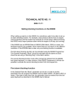
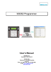
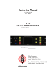
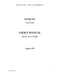
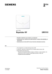
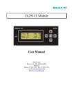
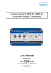
Analog Alarm Annunciator M3000
User’s Manual
SELCO A/S
Betonvej 10 – DK-4000 Roskilde
Denmark
Phone: 45 7026 1122 - Fax: 45 7026 2522
e-mail: [email protected]
www.selco.com
Analog Alarm Annunciator M3000
M3096A-31E
Table of contents
1. INSTALLATION ............................................................................................................................. 5
1.1 Dimensions .............................................................................................................................. 6
2. CONNECTION .............................................................................................................................. 7
2.1 Power Supply........................................................................................................................... 8
2.2 Inputs ....................................................................................................................................... 8
2.2.1 Voltage and Current Sources ............................................................................................ 9
2.2.2 Potential Free Contacts..................................................................................................... 9
2.2.3 Mixed Sensor Types.......................................................................................................... 9
2.2.4 PT100, Thermocouples and Pressure Sensors............................................................... 10
2.3 Open Collector Outputs ......................................................................................................... 11
2.3.1 ALARM OUT ................................................................................................................... 11
2.3.2 SIREN ............................................................................................................................. 11
2.3.3 OUT1 - OUT14 ................................................................................................................ 11
3. CONFIGURATION ...................................................................................................................... 12
3.1 Physical Input......................................................................................................................... 14
3.1.1 Input Type ....................................................................................................................... 14
3.1.2 LCD Unit.......................................................................................................................... 14
3.1.3 Input Lower Reference .................................................................................................... 14
3.1.4 LCD Lower Reference..................................................................................................... 14
3.1.5 Input Upper Reference .................................................................................................... 14
3.1.6 LCD Upper Reference..................................................................................................... 15
3.1.7 Miscellaneous.................................................................................................................. 15
3.2 Logical Input........................................................................................................................... 15
3.2.1 Average Calculation ........................................................................................................ 15
3.3 Alarm...................................................................................................................................... 16
3.3.1 Input Reference............................................................................................................... 16
3.3.2 Set Point.......................................................................................................................... 16
3.3.3 LCD Description .............................................................................................................. 17
3.3.4 Delay ............................................................................................................................... 18
3.3.5 LED ................................................................................................................................. 18
3.3.6 Output.............................................................................................................................. 18
3.3.7 Flags................................................................................................................................ 18
3.3.7.1 Block ......................................................................................................................... 18
3.3.7.2 Control Mode ............................................................................................................ 19
4. OPERATION ............................................................................................................ ...................20
4.1 Keyboard Dialog .................................................................................................................... 20
4.1.1 Siren Deactivation ........................................................................................................... 20
2
SELCO A/S
M3096A-31E
Analog Alarm Annunciator M3000
4.1.2 LED Reset....................................................................................................................... 20
4.1.3 Output Deactivation......................................................................................................... 21
4.2 Alarm Indication ..................................................................................................................... 21
5. PROGRAMMING ........................................................................................................................ 21
5.1 Physical Input ........................................................................................................................ 22
5.1.1 Input Type ....................................................................................................................... 22
5.1.2 LCD Unit.......................................................................................................................... 22
5.1.3 Input Lower Reference.................................................................................................... 22
5.1.4 LCD Lower Reference..................................................................................................... 23
5.1.5 Input Upper Reference.................................................................................................... 23
5.1.6 LCD Upper Reference..................................................................................................... 23
5.1.7 Miscellaneous ................................................................................................................. 24
5.2 Logical Input .......................................................................................................................... 24
5.2.1 Average........................................................................................................................... 24
5.3 Alarm ..................................................................................................................................... 25
5.3.1 Input Reference............................................................................................................... 25
5.3.2 Set Point.......................................................................................................................... 25
5.3.3 LCD Description .............................................................................................................. 26
5.3.4 Delay ............................................................................................................................... 26
5.3.5 LED ................................................................................................................................. 26
5.3.6 Output ............................................................................................................................. 26
5.3.7 Flags ............................................................................................................................... 27
6. LOW-LEVEL CONFIGURATION................................................................................................. 27
6.1 General Constants................................................................................................................. 27
6.1.1 A00 - E²PROM Initialization ............................................................................................ 27
6.1.2 A01 - Function Test......................................................................................................... 27
6.1.3 A03 - Device Number...................................................................................................... 27
6.1.4 A05 - RS232 Baud Rate.................................................................................................. 28
6.1.5 A06 - RS485 Baud Rate.................................................................................................. 28
6.1.6 A07 - Remote Reset........................................................................................................ 28
6.1.7 A08 - Output Follows Input.............................................................................................. 28
6.1.8 A09 - Remote LED Test .................................................................................................. 28
6.1.9 A10 - Block...................................................................................................................... 28
6.1.10 A11 - M1000 Reset Function ........................................................................................ 28
7. SPECIFICATIONS ...................................................................................................................... 30
8. APPENDIX 1 - APPLICATION EXAMPLES................................................................................ 31
8.1 Current Transmitter 4 - 20 mA ............................................................................................... 31
8.1.1 Connection ...................................................................................................................... 31
8.1.2 Configuration................................................................................................................... 31
SELCO A/S
3
Analog Alarm Annunciator M3000
M3096A-31E
8.2 Potential Free Contacts ......................................................................................................... 32
8.2.1 Connection ...................................................................................................................... 32
8.2.2 Configuration ................................................................................................................... 32
8.3 Average Temperature Alarms (Engine Application)............................................................... 32
8.3.1 Connection ...................................................................................................................... 33
8.3.2 Configuration ................................................................................................................... 33
Important note:
This document contains information on a new product. Specifications and information herein are
subject to change without notice. Please advise SELCO for further details on latest developments.
4
SELCO A/S
M3096A-31E
1
Analog Alarm Annunciator M3000
INSTALLATION
The M3000 is designed for flush mounting. Outside dimensions are H x W x D = 144 x 144 x
70mm. A cut out with dimensions H x W = 138 x 138mm must be made in order to install the unit in
the switchboard cabinet.
Make sure that there is enough space in the switch board cabinet behind the unit to install the plugin connectors and the cables. An installation depth of between 75 and 90mm is recommended.
The M3000 is secured to the switch board plate through the use of the 4 mounting/fixing brackets
included in the package.
Install the M3000 as described below.
• Find a location in the switch board cabinet with enough installation depth to house the M3000
unit. Make sure that the selected location is also satisfactory from the operator’s point of view.
• Keep in mind that it may be convenient to make room for the RS232 connection if you plan to do
external programming from a PC in the future.
• Make a cut out with the dimensions H x W = 138 x 138mm in the cabinet plate.
• Remove all the plug-in connectors located at the rear side of the unit.
• Make sure the rubber gasket is in place behind the unit front plate. This gasket is necessary to
ensure compliance with the IP54 requirements.
• Insert the unit into the cut out.
• Place the 4 mounting/fixing brackets in the small rectangular cut outs located at the top and
bottom plates of the unit.
• Tighten the 4 mounting/fixing brackets with a screwdriver until the unit is firmly seated.
Be careful not to make the connection cables too short. Extending the length of all cables with
around 100mm will ease any later service task.
SELCO A/S
5
Analog Alarm Annunciator M3000
1.1
M3096A-94E
Dimensions
70mm
144mm
144mm
4.5mm
Cut out 138 x 138mm
6
SELCO A/S
M3096A-94E
2.
Analog Alarm Annunciator M3000
CONNECTION
The M3000 includes a number of plug-in connectors. Each of these connectors houses a number
of screw terminals to which the cables are connected. The plug-in terminals can easily be attached
and removed without the use of any tools. The plug-in connectors include the connection terminals
for the power supply, the 24 sensor inputs and the 16 open collector outputs.
The figure below shows the rear side of the M3000 unit.
8 input groups
Includes 3 input
terminals for
analog or digital
signals and 1
GND terminal for
common reference
RS232
Used for remote
configuration with
the SELCO M3092
Programmer
ALARM//PROG
PROG
ALARM
Switchto
toselect
select
Switch
alarmor
or
alarm
programming
mode
programming mode
RS485
Used for
communication with
the SELCO H0300
Event Logger or
another bus system
16 open
collector
outputs
Power supply
and dimming
LCD contrast
The M3000 includes 8 groups of input terminals. Each group is physically represented by a plug-in
connector that holds 3 input terminals, “IN1”, “IN2” and “IN3”, and one common reference terminal
“GND”. Be sure not to confuse the physical inputs with the logical inputs “INA”, “INB” and “INC”.
The logical inputs has no related input terminals, they are imaginary inputs intended for average
calculation based upon other inputs. The logical inputs are described later in this manual.
Alarm annunciation is done through 48 programmable alarms. Each alarm can be programmed to
monitor a physical or logical input. Alarm annunciation takes place when the input signal exceeds
the set point of the alarm. An alarm is able to control one LED and one open collector output.
Control of external equipment is possible through the use of 16 open collector outputs. 14 of these
outputs, “OUT1” to “OUT14”, are user programmable for alarm dependent control. The “SIREN”
output is mainly intended for the control of an acoustic warning device. An active “AL.OUT” signal
indicates that an alarm condition exists on the unit.
The M3000 includes two interface standards for serial data communication. The RS232 interface is
intended for point to point data communication between the M3000 and another device, e.g. a PC.
RS485 is intended for long distance bus communication between multiple M3000 units.
SELCO A/S
7
Analog Alarm Annunciator M3000
M3096A-94E
The small switch on the left side of the rear panel is used to change between program mode and
alarm mode. In program mode the functions of the unit can be programmed. Alarm mode is the
normal alarm mode. The potentiometer at the bottom behind the front plate provides contrast
adjustment for the liquid crystal display (LCD).
2.1
Power Supply
The M3000 requires a supply of +24V DC. The supply wires must be connected between terminal
120 (+24V DC) and terminal 121 (GND). The supply voltage is required to be within the range of
+18V DC to +30V DC, this voltage range corresponds to ±30% of the nominal supply voltage. The
current consumption from the +24V DC supply is less than 400mA.
The power supply plug-in connector of the M3000 includes 3 terminals, one for +24V DC, one
GND reference and one terminal DIM for dimming of the LED’s on the front panel of the unit. For
dimming purpose a potentiometer of 100k is connected between the terminal 122 (DIM) and
terminal 121 (GND).
The connection of the +24V DC supply and the potentiometer for dimming is shown below.
DIM
100K
Important note: The power supply used for the M3000 and its interface components should be
operative and stable under all conditions. The M3000 is in most cases required to be operative at
all times - even under a possible “black out” condition.
2.2
Inputs
The M3000 includes a total of 24 inputs. Each of these inputs will accept the connection of one
sensor. The sensor can be a PT100 or a thermocouple supplying a current or voltage signal
through the use of a standard transmitter. It is also possible to connect a potential free contact to
an input. The sensors need not be for temperature, it is in fact possible to connect any sensor that
is, in some way, able to provide a DC voltage or current signal.
The input types are 10V DC, 24V DC and 0-20mA. Please note that the voltage on an input
terminal is measured according to the common reference of the unit (GND). The supply GND
terminal and the group plug-in GND terminals are connected together.
8
SELCO A/S
M3096A-94E
Analog Alarm Annunciator M3000
2.2.1 Voltage and Current Sources
Below are two examples. These examples show the two most common input configurations. The
figure to the left shows the connection of 3 voltage sources supplying a voltage within the range of
10V DC. The figure to the right shows how to connect 3 current sources.
2.2.2 Potential Free Contacts
The M3000 is capable of annunciating digital alarms. In this case the sensor will be some kind of
potential free contact. The potential free contact will actually control the connection of a voltage
source
The figure below shows 3 potential free contacts on the same input plug-in connector. The
reference of the contacts is +24V DC.
2.2.3 Mixed Sensor Types
The previous examples of how to connect different sensors involved a whole input plug-in
connector (3 inputs) at one time. However it is also possible to mix the sensor types within an input
plug-in connector. Please refer to the example below.
The example above shows 3 different sensors connected to the same input plug-in connector.
Input terminal “IN1” is connected to a potential free contact to +24V DC.
Input terminal “IN2” is connected to a current source.
SELCO A/S
9
Analog Alarm Annunciator M3000
M3096A-94E
Input terminal “IN3” is connected directly to a voltage source providing a voltage difference
between “IN3” and “GND”.
2.2.4 PT100, Thermocouples and Pressure Sensors
Note that there is a wide range of transmitters on the market that provide an output signal of 4 to
20 mA. A transmitter of this type is actually a current source and should be connected as such. An
example describing the connection of a Kamstrup-Metro Flex Temp transmitter is shown below.
The connection of other 4-20 mA transmitters is similar to this example.
The transmitter shown above works like a current gate. It releases only 4mA at 0°C and 20mA at
100°C.
Two Danish companies that supplies 4-20mA transmitters:
• Kamstrup A/S
• PR Electronics
Jacob Knudsens vej 12,
DK-8230 Åbyhøj
Phone: +45 89 31 76 11
Fax: +45 86 25 65 77
Lerbakken 10,
DK-8410 Rønde
Phone: +45 86 37 26 77
Fax: +45 86 37 30 85
The SELCO PT100 6 Way Transmitter M1500 provides a cost-effective solution and includes 6
current transmitters in one box to be connected to PT 100 resistors. The following diagram shows
the connections of the M1500.
4-20mA
OUT 6
OUT 5
PT100 5.
GND
4-20mA
OUT 4
+
GND
4-20mA
GND
PT100 4.
PT100 6.
17 18 19 20 21 22 23 24 25 26 27 28 29 30 31 32
M1500
10
10 11 12 13 14 15 16
PT100 3.
OUT 3
PT100 2.
9
+
GND
8
4-20mA
7
OUT 2
6
GND
5
4-20mA
PT100 1.
4
OUT 1
3
GND
2
4-20mA
1
SELCO A/S
Analog Alarm Annunciator M3000
M3096A-94E
The example below shows connections to one input group of M3000. For more details see
separate data sheet M1595.
17 18 19 20 21 22 23 24 25 26 27 28 29 30 31 32
M1500
6
7
8
PT100 2.
9
10 11 12 13 14 15 16
PT100 3.
OUT 3
5
OUT 2
PT100 1.
4
GND
3
OUT 1
2
GND
1
+
-
2.3
Open Collector Outputs
The M3000 includes a total of 16 open collector outputs. Each output is capable of driving an
external LED or a relay. One output will indicate that an alarm is present on the M3000 and
another output is mainly intended for siren control. The remaining 14 open collector outputs can be
used for group alarms or alarm dependent control of external equipment. Open collector outputs
are digital outputs that are either on or off.
2.3.1 AL.OUT
The “AL.OUT” (115) output is an open collector output. Like all other open collector outputs, this
output is at GND level when active and at +24V DC level when inactive. The “AL.OUT” output is
active as long as one or more alarms are present on the M3000. If alarms are already present on
the unit when a new alarm is annunciated, the output is briefly deactivated for about 500 ms to
indicate the annunciation of a new alarm.
2.3.2 SIREN
The terminal marked “SIREN” (116) is an open collector output intended for controlling an acoustic
warning device. This output is activated to annunciate a new alarm. The output is deactivated by
the first press of the “C” key, located on the M3000 front plate. Output is at GND level when active,
and at +24V DC level when inactive.
The figure below shows how to connect a relay for control of the siren. The relay is shown in its deenergized state.
2.3.3 OUT1 - OUT14
The M3000 includes 14 open collector outputs intended for general use. These outputs can be
programmed to activate upon annunciation of any one of the 48 alarms that the M3000 includes.
SELCO A/S
11
Analog Alarm Annunciator M3000
M3096A-94E
An output is activated together with the annunciation of the controlling alarm. The output will stay
active until the operator acknowledges the alarm from the M3000 keyboard. Second press of the
“C” key will deactivate the output.
An output will operate according to an “OR” function if controlled by more than one alarm. This
means that an output will be active if either one of the controlling alarms is active.
The figure below gives an example of how to indicate the state of output 3 and 5 on two remote
LED’s. Normally the outputs are intended for driving relays.
The open collector output “AL.OUT” can be used to signal the appearance of multiple alarms
controlling the same output.
An open collector output will not drive anything. It works only as an electronic contact to GND.
3.
CONFIGURATION
The configuration of the M3000 unit consists of a number of parameters that describe the set-up of
the 24 physical inputs, the 24 logical inputs and the 48 alarms.
The configuration of a physical or logical input includes parameters that describe the expected
signal type and range, the unit of measurement and the relationship between the input signal, in
volt or ampere, and the measurement in °C, kW or whatever unit that is to be measured. On top of
this the logical inputs have one additional parameter with 12 cells that holds references to the
inputs that takes part in the average calculation performed by the logical input.
The configuration of an alarm includes parameters that describe the reference of the input, to
which the alarm has been assigned, a set point (fixed or dynamic) that defines the level of alarm
annunciation, a delay and references to the LED and open collector output that are to be activated
in order to annunciate the alarm. A 10 character user defined text string holds the description of the
alarm.
The parameters of the configuration must be adjusted before the unit can be put into operation.
Note that it is only necessary to adjust the parameters of the active inputs and alarms. Inputs
having no connection to a sensor should be disabled by setting the input type parameter to “Off”.
Alarms that are not in use should have their input reference parameter set to “Off” as well.
12
SELCO A/S
M3096A-94E
Analog Alarm Annunciator M3000
The configuration parameters are stored inside a non-volatile memory circuit (an E²PROM) located
inside the unit. The non-volatile memory is kept intact - even if power supply is disconnected for a
long period.
It is possible to program the configuration of the M3000 in two different ways. The first way is to
enter the configuration parameters directly from the front plate keyboard of the M3000. This
method is also referred to as “LCD programming”. During LCD programming, the configuration
parameters are displayed in the liquid crystal display while the operator is allowed to alter the state
of each parameter. The other way is to program the M3000 through the unit RS232 interface.
Important note: The switch located on the rear left side of the M3000 must be in program mode
(“PROG”) to allow programming from either the keyboard and/or the RS232 interface.
The procedure of LCD programming is much like the programming procedures that you might
already know from VCRs, televisions and other microprocessor based products. The operator is
able to move around between the configuration parameters through the use of a selection key.
Each parameter of the configuration can be modified by toggling, or by simply entering the new
value from the numeric keys of the unit keyboard.
RS232 programming involves the use of a standard PC with Windows 95, Windows 98, Windows
2000 or Windows XP operation system. SELCO has developed a user-friendly application called
the M3092 Programmer. This application enables the operator to program the M3000 through use
of the built-in RS232 interface. The parameters are entered in very much the same way as in a
Microsoft Excel Spreadsheet. This method of programming is ideal for setting up a M3000 from
scratch. The SELCO M3092 Programmer is validating all data that is entered, and all the
configuration parameters can be modified in the program. The configuration can be stored on disk
and it can be printed out for documentation. The data can also be exported to Excel.
Sensors are connected to the M3000 unit through the input terminals included in the 8 plug-in
connectors located at the rear side of the unit. Each of the 8 input plug-in connectors is referred to
as a “group”. Each group includes 3 input terminals named “IN1”, “IN2” and “IN3”, and one
common reference terminal named “GND”.
As mentioned earlier, a group refers directly to the 3 inputs located in an input plug-in connector.
Note however that each of the 3 physical inputs located in a group can be used with different types
of sensors.
Seen from a configuration point of view, each group also includes 3 logical inputs and 6 alarms.
The logical inputs are configured like the physical inputs but they have no related input terminal.
The logical inputs are used to do average calculations from up to 12 physical or logical inputs.
Each of the 6 alarms refers directly to a physical or logical input. The input does not have to be
within the same group as the alarm. It is possible to assign all 48 alarms to the same input.
Normally one would assign between one and 4 alarms to one input, two alarms would give every
one of the 24 physical inputs one low and one high level alarm.
SELCO A/S
13
Analog Alarm Annunciator M3000
M3096A-94E
3.1 Physical Input
The parameters included in the configuration of a physical input are described below. The table
shows the parameters of the 3 physical inputs encapsulated in one group.
Inp:
Inp:1
Inp:2
Inp:3
InpTp:
20 mA
10 V
24 V
LCDU:
˚C
kW
V DC
InpLo:
4
0
0
LCDLo:
0
0
0
InpUp:
20
10
24
LCDUp:
600
25
24
Misc:
0
0
0
3.1.1 Input Type
The “InpTp” parameter defines both the type of input signal and the expected maximum range of
that signal. The range defined by the “InpTp” parameter must cover the expected range of the
signal provided by the sensor connected to the input. Example: “InpTp” should be set to 20 mA in
order to accept the connection of a 4-20 mA transmitter. Setting this parameter to “Off” will
completely disable the physical input.
3.1.2 LCD Unit
This parameter defines the unit of measurement. The parameter holds a combination of 4
characters. The selection of these 4 characters will not affect the operation of the M3000 in any
way, the contents of the “LCDU” parameter is only used for indication in the display.
Example, likely LCD units: “˚C”, “˚F”, “Volt” and “kW”.
3.1.3 Input Lower Reference
Defines the lower reference value of the input signal. The “InpLo” parameter is used together with
the “LCDLo” parameter to form the relation between the actual input signal, in voltage or current,
and the measured value expressed in the unit defined by the LCD unit parameter.
Example, consider the following parameter set-up:
InpTp: 20 mA
LCDU: ˚C InpLo: 4
LCDLo: 0
This will tell the M3000 that a current signal between 0 and 20 mA is expected at the input terminal
and that the desired unit of measurement is degrees Celsius, indicated by the “˚C” in the LCD unit
parameter. The parameters “InpLo” and “LCDLo” indicate that 4 mA on the input should be
translated to 0 C in the LCD.
3.1.4 LCD Lower Reference
This parameter holds the low reference point of the measured value and defines a low reference
relation together with the “InpLo” parameter. Please refer to the prior explanation of the “InpLo”
parameter for further details.
3.1.5 Input Upper Reference
The “InpUp” parameter defines the upper reference point of the input signal. As with the lower
reference, the upper reference is used to form a relation between the actual input signal, in voltage
or current, and the measured value expressed in the unit defined by the LCD unit parameter.
Example, consider the following parameter set-up:
14
SELCO A/S
Analog Alarm Annunciator M3000
M3096A-94E
InpTp: 20 mA
LCDU: ˚C InpUp: 20
LCDUp: 600
The above configuration will inform the M3000 that a current signal is expected on the input. The
combination of the “InpUp” and “LCDUp” parameters forms the relation, 20 mA measured on the
input should bring the M3000 to show 600˚C in the LCD. Please refer to the description of the
“InpLo” parameters as well.
3.1.6 LCD Upper Reference
Defines the upper reference point of the measured value. This parameter works together with the
“InpUp” parameter to define a relation. Please refer to the above description on the other reference
points.
3.1.7 Miscellaneous
This parameter is intended for future use. At present the value has no affect on the operation of the
unit.
3.2
Logical Input
The parameters included in the configuration of a logical input are described below. The table
shows the parameters of the 3 logical inputs encapsulated in one group. Logical inputs are used
and referred to like physical inputs, but a logical input has no related input terminal. Logical inputs
are used to represent the average of the measurements collected from up to 12 other physical or
logical inputs.
Inp:
Inp:A
Inp:B
Inp:C
InpTp:
20 mA
10 V
24 V
LCDU:
C
kW
V DC
InpLo:
4
0
0
LCDLo:
0
0
0
InpUp:
20
10
24
LCDUp:
600
25
24
Misc:
0
0
0
Avrg:
01 11
02 21
07 Off
Please turn to the pervious description of the physical input parameters for an explanation of the
following parameters also included in the configuration of each logical input:
InpTp, LCDU, InpLo, LCDLo, InpUp, LCDUp and Misc
These parameters should always have the exact same value as the inputs included in the average
calculation performed by the logical input.
3.2.1 Average Calculation
The very reason for the existence of the logical inputs is the need for average calculation. One
logical input will perform an imaginary measurement that will correspond to the average of the
measurements from up to 12 physical or logical inputs.
Each of 12 input references can point to any physical or logical input. Input references that are not
required must be set to “Off” using the “C” key. In the example above “01 11” means that reference
# 01 points to group 1 input 1 (11). “02 21” means that reference # 02 points to group 2 input 1
(21). “07 Off” means that reference # 07 are not used and therefore set to “Off”.
SELCO A/S
15
Analog Alarm Annunciator M3000
M3096A-94E
Important note: It is very important that all inputs referred to by the average parameter have
compliant parameter values assigned. The logical input itself must also comply with this rule.
Failing to do so may impose a significant error on result returned by the average calculation.
The average calculation of a logical input can be described by the formula below:
N
IN n
Average
n 1
N
The variable “Average” represents the measurement on the logical input. “N” is the number of
physical and logical inputs that takes part in the average calculation (max. 12). “INn“is the
measurement of each physical or logical input. Note that the measurement of the logical input
equals the sum of all input measurement divided by the number of measurements.
Example, consider one diesel engine with 12 cylinders. The temperature measurement on each
cylinder could be picked up through 12 physical inputs. A logical input might then be used to
“measure” the average temperature on all 12 cylinders. It is also possible to use the average
temperature as a dynamic set point for one or more alarms.
3.3
Alarm
The parameters included in the configuration of an alarm are described below. The table shows the
parameters of the 6 alarms encapsulated in a group.
Alr:
InpRf:
Set:
Text:
Delay:
Alr:1
Alr:2
Alr:3
Alr:4
Alr:5
Alr:6
11
11
21
22
31
32
<0
> 100
< 10
> 10
> 1000
< 1A 30
Freezing
Boiling
Low press
High press
Overload
Average
100 x 10 ms
100 x 10 ms
30 x 10 ms
30 x 10 ms
10 x 1 min
15 x 1 s
LE
D:
L01
L01
L02
L03
L14
L15
Outp:
Flags:
O01
O01
O02
O02
Off
Off
00000000
00000000
00000000
00000000
00000000
00000000
3.3.1 Input Reference
The “InpRf” parameter holds the reference to the input to which the alarm has been assigned. The
“InpRf” parameter includes two decimals, the first decimal holds the number of the group, and the
last decimal holds the number of the input.
Example: An input reference of “31” indicates a reference to input 1 (IN1) of group 3. Set this
parameter to “Off” to disable the alarm.
3.3.2 Set Point
The “Set” parameter defines the set point of the alarm. The set point describes the level and area
of alarm condition relative to the measured value. The set point is always expressed in the unit
indicated by the LCD unit parameter of the surveyed input.
16
SELCO A/S
Analog Alarm Annunciator M3000
M3096A-94E
The set point parameter consists of an operator, a sign and a value. In some cases the sign is
replaced by a logical input reference.
The set point value can be a fixed value (e.g. a fixed temperature) or a dynamic reference with a
plus/minus offset. The average calculated by a logical input can be used as a dynamic set point.
The fixed valued used together with a dynamic reference indicates a plus/minus offset from the
measurement of the dynamic reference. In the example above for alarm 6 “1A” is the dynamic
reference and “30” is the plus/minus offset. The operator “<” will be disregarded in this case.
The function of a fixed set point is quite simple. The alarm is annunciated when the measurement
of the related input passes above or below the set point.
Input > fixed set point => Alarm
or
Input < fixed set point => Alarm
The matter gets a little bit more complicated with the dynamic set point. The figure below shows
the relation between the dynamic set point (the logical input) and the plus/minus offset.
Dynamic Set Point
Level
Alarm
Input ref.
Upper offset
Set point
Lower offset
Time
The middle line in the above figure describes the dynamic set point. Note that the level of the set
point changes over time. It simply follows the measurement of the related logical input. The two
lines above and beneath the dynamic set point are the offsets. The offsets define the actual alarm
levels in relation to the dynamic set point. Alarm condition exists if the measurement of
the related input passes above the upper offset or below the lower offset. The measurement of the
related input is indicated by the dotted line.
Note that the related input is not included in the average, as this would influence the average value
in an unwanted manner for such applications.
3.3.3 LCD Description
This parameter holds a 10 character text that is shown on the LCD together with the actual
measurement and the alarm set point. The alarm text is only used for indication and the choice of
characters will not affect the operation of the M3000 in any way.
SELCO A/S
17
Analog Alarm Annunciator M3000
M3096A-94E
3.3.4 Delay
The alarm delay parameter can be used to prevent small spikes in the related input signal from
activating the alarm. Long alarm delays are useful for preventing frequent annunciation of less
essential alarms. An alarm condition will exist when the input signal has exceeded the alarm set
point for a time period longer than the time specified by the delay parameters. The alarm delay
consists of a time value and a multiplication factor.
Important note: It is very important that the smallest possible factor is selected to form the delay.
The factor will represent the resolution of the timer that operates the delay. A 10 seconds delay
should be made from a time value of 100 and a multiplication factor of 100 ms. Selecting a time
value of 1 and a multiplication factor of 10 seconds would result in a less accurate delay function.
The time value should normally be between 10 and 100. When using the M3092 M-Programmer it
is not necessary to worry about time value and multiplication factor. The delay should just be
entered in seconds and the program will take care of the rest. The minimum delay is 300 ms.
An alarm will be annunciated once the level defined by the alarm set point has been continuously
ex- or subceeded for the time defined by the alarm delay.
3.3.5 LED
The “LED” parameter holds a reference to the LED that is to be activated upon alarm condition.
Any of the 24 LED’s located on the unit front plate can be activated to visual annunciation of an
alarm, and one or more alarms can use the same LED for indication. Setting this parameter to “Off”
will disable LED indication for the alarm.
3.3.6 Output
Setting the “Outp” parameter will enable to unit to activate one of the 14 open collector outputs
upon alarm condition. The output can be used to control external lamps or relays. The “Outp”
parameter should be set to “Off” when no external control is required.
3.3.7 Flags
The 8 bits of the “Flags” parameter control specific alarm related functions. The 8 bits work like 8
programming contacts. A “contact” is on when the bit is set to one and the “contact” if off when a bit
is set to zero. The bits of the “Flags” parameter are numbered from 0 to 7; number 0 is the bit
furthest to the right.
3.3.7.1 Block
Bit number 7, the first bit from the left, represents the status of the alarm block function. The
related alarm will be blocked by the block control input when this bit is set to “1”. Input terminal one
of group 8 can be configured to operate as the block control input. Please refer to the description of
the low level configuration.
Example: Most pressure alarms from an engine must be blocked until the engine has reached
normal revolutions. Without blocking the M3000 will report pressure alarm while the engine is off
duty (not running).
18
SELCO A/S
M3096A-94E
Analog Alarm Annunciator M3000
3.3.7.2 Control Mode
Bit number 6, the second bit from the left, represents the status of the alarm control mode. The
alarm will be in control mode when bit number 6 is set to “1”. Control mode is intended for level
dependent control of external equipment. External equipment can be connected to the 14 open
collector outputs of the M3000.
In normal alarm mode the open collector output (if any) of the alarm will be activated on alarm
condition, the LED (if any) of the alarm will be flashing and the two common collector outputs
“AL.OUT” and “SIREN” will be activated. The alarms will stay active until the operator
acknowledges the alarms from the M3000 keyboard or until the remote reset function is used.
In control mode the open collector outputs are used for level dependent control of external
equipment. The outputs are not considered as alarm outputs, only as control outputs. In control
mode no reset is needed to disable the LED and the open collector control output, when the
condition for the control signal no longer exists. The two common open collector outputs “AL.OUT”
and “SIREN” are not activated in control mode.
The LEDs controlled by “alarms” in control mode will not flash, they will have steady light for
“alarm” condition (exceeded set point), and no light for normal condition.
Control mode can be used for switching on and off heating, via one of the open collector outputs,
depending on the actual temperature. The heating will be switched on, once the temperature drops
below a pre-set level, and it will be switched off again when the temperature is back at the pre-set
level.
A delay on the “alarm” can be used as a kind of hysteresis in order to prevent frequent toggling
between heating on and off.
3.3.7.3 Hysteresis Mode
This section describes the hysteresis function of the M3000. This function is available in the
M3000, if it has an EPROM date of 040101 (4 January 2001) or younger.
The hysteresis function is typically used for “alarms” in control mode (see previous section) to
switch on and off external equipment at a pre-set level with an adjustable hysteresis.
The hysteresis for an “alarm” is enabled by setting bit number 5 (third bit from the left) of the
“Flags” parameter for the “alarm” to 1. Setting it to 0 will switch off the hysteresis mode
Example: We want to switch on heating when temperature drops below 57°C and switch it off
again when the temperature is above 63°C. That means we want to switch on and off at 60°C with
a hysteresis of ±3°C.
The actual hysteresis should be entered in percent as a General Parameter using the SELCO
M3092 M-Programmer or from the keyboard as described in the description of the low level
configuration.
In our case where we use a 4-20mA, 0-100°C transmitter at the input, 3°C is equal 0.6mA. The
0.6mA is equal 2.4% of the full-scale level 20mA.
SELCO A/S
19
Analog Alarm Annunciator M3000
M3096A-94E
Hysteresis mode is enabled for all “alarms” where this hysteresis is wanted by setting bit number 5
of the “Flags” parameter to 1. “Alarms” set into hysteresis mode will now have a hysteresis of the
entered value (± 2.4% of full-scale level in the above example).
4.
OPERATION
The M3000 unit is operated from the front plate keyboard. Some of the keys included in the
keyboard layout have different meaning depending on the operational state of the unit. Generally
the unit can be in one of two different operational states; alarm surveillance mode or programming
mode. Please make sure that the correct mode is selected on the switch at the rear side of the unit.
4.1
Keyboard Dialog
The figure below shows the various functions available through use of the unit keyboard.
Mode Selector
Used to switch between modes. During
alarm indication mode this key toggles
the indication between normal alarm
description and physical voltage or
current measurements.
Master reset, LCD test &
parameter selector
Stops the siren and performs master
reset during normal alarm mode. Used
for lamp test after pressing the “M” key
in normal alarm indication mode. Used
for parameter selection during
programming mode.
Alarm selector &
parameter toggle
While in alarm indication mode
these two keys are used to
select an alarm for indication in
the LCD. The arrow keys will
toggle the value of any multiple
choice parameter during
programming mode.
Numeric keys
While in normal alarm indication mode
the keys are used to toggle between
the alarms represented by the nearby
LEDs for indication in the LCD. Used
for entering numeric data into value
parameters during programming
mode.
Description covers the keys to the right
as well.
Backspace
Acts as a backspace key while
programming mode is active.
Operator selector
While in programming mode the
key will toggle between
sign/operator and value while
editing numeric data.
4.1.1 Siren Deactivation
The siren is activated together with every new alarm annunciated on the M3000. Alarms not
controlling a LED or an open collector output are only indicated on the LCD, these alarms will also
cause the siren output to energize. The siren is stopped by the first press on the “C” key of the
M3000 keyboard.
4.1.2 LED Reset
Each of the 48 alarms of the M3000 can be programmed to control one of the 24 LEDs located on
the front plate. A LED will start flashing once the controlling alarm is annunciated. A flashing LED
indicates a new alarm that needs acknowledgment.
First press on the “C” key will stop the siren, second press will acknowledge the LED and change
the flashing to steady light, and the third press will turn off the LED providing the alarm set point is
20
SELCO A/S
M3096A-94E
Analog Alarm Annunciator M3000
no longer exceeded. Note that the second press will also disable any open collector output
controlled by the alarm.
4.1.3 Output Deactivation
Each of the 48 alarms of the M3000 can be programmed to control one of the 14 open collector
outputs located in the two 8 pole plug-in connectors at the rear side of the unit.
The output controlled by an alarm is deactivated at the second press of the “C” key.
4.2
Alarm Indication
The operator is able to switch to alarm indication mode by setting the switch “ALARM / PROG” on
the rear of the unit to “ALARM” and then pressing the “M” key of the keyboard until an “A” is visible
in the top left corner of the LCD.
The “M” key can be used to toggle between normal alarm indication mode and a mode where
physical voltage or current measurements are indicated in the LCD.
When in alarm indication mode, the LCD will show the actual measurement on the sensor
connected to the input referred to by the indicated alarm. The alarm set point and text description
is indicated as well.
The M3000 will automatically display the last incoming alarm in the LCD, but the operator is also
able to select a specific alarm for indication by pressing the up/down arrow keys of the M3000
keyboard until the alarm appears in the LCD. Alternatively the numeric keys will indicate alarms
associated by the 2 nearby LED's. Pressing the numeric keys will cause the indication on the LCD
to toggle between these two alarms. However the indicated alarm will again change once another
alarm is activated.
Alarm annunciation by the LED’s and open collector outputs is always active for all alarms
although only one alarm is indicated in the LCD.
5.
PROGRAMMING
The unit must be put into programming mode before the configuration of the 24 physical inputs, the
24 logical inputs and the 48 alarms can be altered.
Programming mode is enabled by setting the switch “ALARM / PROG” on the rear of the unit to
“PROG” and then pressing the “M” key of the keyboard until the text “Prg” is made visible in the top
left corner of the LCD.
Note that in programming mode all LED’s on the front of the unit will be on in order to indicate
programming mode. This is done in order to prevent forgetting to set the unit back in alarm mode
after programming the unit.
Normally programming should be done through the RS232 interface using the configuration
software M3092 M-programmer, which is a user-friendly software package, where the parameters
SELCO A/S
21
Analog Alarm Annunciator M3000
M3096A-94E
are entered very much like in a spreadsheet, such as e.g. Microsoft Excel. However, it is also
possible to enter the parameters from the front panel keyboard as described in the following.
Important note: Altered configuration parameters are active only a few seconds after being
changed in the configuration. No enter or return key must be pressed to acknowledge new
adjustments to the configuration. Please wait a few seconds after entering the last parameters
before setting the unit back into alarm mode. This will make sure that the units program is updated.
5.1
Physical Input
The M3000 includes a total of 24 physical inputs located in 8 groups. Each group holds 3 physical
inputs and the configuration of these physical inputs will affect the function of the related hardware
input terminals encapsulated by the plug-in connector at the rear side of the unit.
To select the group press the “C” key a number of times to move the cursor to the number located
at the right of the text “Gr:”. Then toggle the group number with the up/down arrow keys until the
desired group reference is shown.
The physical input is selected in the exact same way as the group. Press the “C” key to move the
cursor to the right of the text “Inp:”. Then use the up/down arrow keys to toggle the physical input
reference.
5.1.1 Input Type
The first parameter of the physical input configuration is the input type indicated in the LCD as
“InpTp”. Press the “C” key to move the cursor to the bottom left corner of the LCD, then toggle the
parameters with the up/down arrow keys until the text “InpTp” is shown.
Prg Gr:1 Inp:1
InpTp 20mA
Press the “C” key once more to enter the parameter selection field. Select the desired input type
from the rolling list with the up/down arrow keys.
5.1.2 LCD Unit
The second parameter of the physical input configuration is the LCD unit parameter. Press the “C”
key a couple of times until the cursor is located at the bottom left corner of the LCD. Press the “C”
key once more to enter the text field.
Prg Gr:1
LCDU ????
Inp:1
The LCD unit is made up from a combination of 4 characters. Once in the text field the “←“ key will
select the character to edit. The selected character is toggled with the up/down arrow keys.
5.1.3 Input Lower Reference
The third parameter is the lower input reference. The parameter is first selected by pressing the “C”
key a number of times until the cursor is based in the lower left corner of the LCD.
22
SELCO A/S
M3096A-94E
Analog Alarm Annunciator M3000
Prg Gr:1
InpLo
+
Inp:1
0.000
The next activation of the “C” key will bring the cursor into the parameter field. The “←“ key is then
used for switching between the operator and the value part of the parameter.
Pressing the up/down arrow keys while the cursor is on the operator will toggle the sign between
plus and minus. When the cursor is in the value field the up/down arrow keys will shift the position
of the decimal point. The actual value is entered through use of the numeric keys of the keyboard.
Please note that although the value field can hold any number between -65535 and 65535, it is
important to keep in mind that the limits of this field are determined by the range of the selected
input type. The value is set to zero by pressing the “9” key a couple of times to overflow the field.
5.1.4 LCD Lower Reference
Next parameter is the lower LCD reference. Press the “C” key a couple of times to move the cursor
to the bottom left position of the LCD. Then press the “C” key once more to move into the
parameter field.
Prg Gr:1
LCDLo
+
Inp:1
0.000
The programming of the “LCDLo” parameter is done exactly like described for the “InpLo”
parameter. Toggle the parameter operator and decimal position with the up/down arrow keys, and
switch between the operator and the parameter value with the “←“ key.
5.1.5 Input Upper Reference
The upper input reference is selected by first pressing the “C” key a couple of times to move the
cursor to the bottom left position of the LCD. Then press the “C” key once more to move into the
parameter field.
Prg Gr:1
InpUp
+
Inp:1
0.000
The programming of the “InpUp” parameter is done exactly like described for the “InpLo”
parameter. Toggle the parameter operator and decimal position with the up/down arrow keys, and
switch between the operator and the parameter value with the “←“ key.
5.1.6 LCD Upper Reference
The “LCDUp” is the last of the 4 reference parameters that describes the translation between input
signal and measured value. Go to the LCD upper reference parameter by pressing the “C” key until
the cursor is placed in the bottom left corner of the unit.
Prg Gr:1
LCDUp
+
SELCO A/S
Inp:1
0.000
23
Analog Alarm Annunciator M3000
M3096A-94E
Turn to the description of the “InpLo” parameter programming. The “LCDUp” parameter is
programmed in the same way.
5.1.7 Miscellaneous
This parameter has been included in the input configuration to make room for extra configuration
data that might be necessary in future versions of the M3000.
Prg Gr:1
Misc
+
Inp:1
0.000
The miscellaneous parameter is designed to contain a numeric between -65535 and 65535. The
parameter is selected and altered like the 4 input reference parameters. Move the cursor to the
bottom left corner of the LCD with the “C” key, toggle the parameter selection with the up/down
arrow keys, and switch between the operator and the parameter value with the “←“ key.
5.2
Logical Input
The M3000 includes a total of 24 logical inputs located in 8 groups. Each group holds 3 logical
inputs. The logical inputs are used for average calculation based upon the measurements of up to
12 physical or logical inputs.
To select the group press the “C” key a number of times to move the cursor to the number located
at the right of the text “Gr:”. Then toggle the group number with the up/down arrow keys until the
desired group reference is shown.
The logical input is selected in the exact same way as the group. Press the “C” key to move the
cursor to the right of the text “Inp:”. Then use the up/down arrow keys to toggle the logical input
reference.
The logical inputs shares a number of parameter types with the physical inputs. These parameter
types are, the input type, the LCD unit, the lower and upper reference parameters and the
miscellaneous parameter. However the logical input has one additional parameter, the average
parameter. The average parameter holds the references to the inputs that take part in the average
calculation.
Please turn to the programming description for the physical input to get the explanation for the
shared parameter types, but keep in mind that the logical inputs are named “A”, “B” and “C” instead
of “1”, “2” and “3”.
5.2.1 Average
The last and most essential parameter of the logical input configuration is the average parameter.
Move to the parameter name by pressing the “C” key a number of times. Then press the “C” key
once more to enter the parameter field.
24
SELCO A/S
M3096A-94E
Analog Alarm Annunciator M3000
Prg Gr:1 Inp:1
Avrg: 01 11
The “←” key is used to select between the 12 references that is accepted by each logical input.
Each of the 12 input references can point to any physical or logical input. Use the “C” key to toggle
the input selection for the reference indicated in the LCD. Input references that are not required
must be set to “Off” using the “C” key.
5.3
Alarm
The M3000 unit includes a total of 48 alarms located in 8 groups. Each group includes 6 alarms
and any one of these alarms can be programmed for level surveillance of any one of the 24
physical or logical inputs.
Like the inputs, the alarms are organized in groups, however note that an alarm of one group can
be used to survey the level of an input located in another group.
To select the group move the cursor under the number located to the right of the text “Gr:” by
pressing the “C” key a couple of times, then toggle the group number with the up/down arrow keys
until the desired group is indicated.
An alarm is selected in the same way as the group. Move the cursor to the right of the text “Alr:” by
pressing the “C” key, then change the alarm reference with the up/down arrow keys.
5.3.1 Input Reference
The parameter describing the input reference is called “InpRf” in the LCD. The LCD will look like
shown below when the input reference parameter has been selected.
Prg Gr:1
InpRf 11
Alr:1
The reference is selected with the up/down arrow keys once the cursor has been moved beneath
the reference with a press on the “C” key.
5.3.2 Set Point
The set point parameter is by far the most essential parameters of the alarm configuration. Move
the cursor to the bottom left corner of the LCD and press the “C” key until the text “Setp” appears
above the cursor.
Prg Gr:1
Set: > +
Alr:1
0.000
By pressing the “C” key once more the cursor will be situated under the set point operator. The set
point operator is changed with the up/down arrow keys.
The “←“ key will move the cursor to the other two parts of the parameter. Apart from the operator
the set point has a sign and a value. The sign is omitted when the set point is represented by a
dynamic reference (logical input). The sign is selected with the up/down arrow keys. The value is
SELCO A/S
25
Analog Alarm Annunciator M3000
M3096A-94E
entered using the numeric keys. The up/down arrow keys will alter the decimal position of the value
while the cursor is located under the value.
The LCD snapshot below shows a set point programming session involving a dynamic level.
Prg Gr:1
Set: > 1A
Alr:1
0.000
In this case the operator should be ignored. The alarm set point is represented by the logical input
“A” of group 1. The set point value describes the plus/minus offset from the dynamic set point.
The set point is altered like the reference parameters of the input configuration.
5.3.3 LCD Description
Move to the bottom left corner of the LCD by using the “C” key.
Prg Gr:1 Alr:1
Text ??????????
The describing alarm text is altered by first moving the cursor beneath the text itself, do this with a
single press on the “C” key. The “←“ is then used to choose the character. The up/down arrow
keys will roll the chosen character.
5.3.4 Delay
Move to the bottom left corner of the LCD with a number of presses on the “C” key. Then select the
delay parameter with the up/down arrow keys.
Prg Gr:1 Alr:1
Delay 015 * 10S
Move into the delay parameter with one extra activation of the “C” key. Enter the delay value from
the numeric keys. Switch to the factor with the “←” key and toggle the factor with the up/down
arrow keys.
5.3.5 LED
Select the LED parameter by first moving the cursor to the bottom left corner of the LCD. Press the
“C” key to alter the position of the cursor. Then use the up/down arrow keys to select the
parameter.
Prg
LED
Gr:1
L01
Alr:1
Move the cursor inside the parameter field with the “C” key and toggle the LED reference with the
up/down arrow keys.
5.3.6
26
Output
SELCO A/S
Analog Alarm Annunciator M3000
M3096A-94E
The output of the alarm is selected in exactly the same way as the LED. Please turn to the above
instructions describing the programming procedure for the LED.
Prg Gr:0
Outp O02
Alr:0
5.3.7 Flags
Press the “C” key until the cursor is present in the bottom left corner of the LCD. Then select the
Flags parameter with the up/down arrow keys.
Prg Gr:1 Alr:1
Flags 00000000
The Flags parameter consists of 8 bits that can be either “0” or “1” corresponding to off or on. Move
from bit to bit with the “←” key. Toggle the bit state with the up/down arrow keys.
6.
LOW-LEVEL CONFIGURATION
The configuration parameters described below controls a number of low level functions included in
the M3000. These configuration parameters reside in the unit E²PROM together with the
parameters that describe the input and alarm configuration.
6.1
General Constants
6.1.1 A00 - E²PROM Initialization
Entering the value of 3000 into constant 00 of group “A” will initialize the M3000 E²PROM. This
operation will restore the default configuration for all physical inputs, logical inputs and alarms.
Entering the value of 3033 into constant 00 of group “A” will restore the default configuration for all
physical inputs, logical inputs, alarms, and also the general constants.
Note: The new default configuration will not be loaded until after the power supply has been
interrupted.
6.1.2 A01 - Function Test
Enter the value of 33 into constant 01 of group “A”. This initiates a LED and output test at the next
power up. Press the up/down arrow keys while the test is running to switch to keyboard test.
6.1.3 A02 - Protocol
If the M3000 has an EPROM date of 200901 (20 September 2001) or younger, it is possible to
choose between standard MODBUS-RTU protocol and SELCO BUS protocol for communication
via the RS485 interface. Setting constant 02 to 0 will select SELCO BUS protocol and should be
used when communicating with the SELCO N0300 Process Logger Software. Setting the constant
SELCO A/S
27
Analog Alarm Annunciator M3000
M3096A-94E
to 1 (which is default) will select MODBUS protocol, and this should be used when communication
with the SELCO H0300 Event Logger and most other standard RS485 bus systems.
If the M3000 is older than 20 September 2001 only SELCO Bus is available.
6.1.4 A03 - Device Number
Constant 03 of group “A” holds the device number required for use with the RS485 bus and the
SELCO N0300 Process-Logger or the SELCO H0300 Event Logger. Any value between 1 and 62
is acceptable.
6.1.5 A05 - RS232 Baud Rate
Constant 05 of group “A” holds the data transmission rate of the RS232 interface. Default is 9600
baud. This baud rate must comply with the baud rate selected in the COM port set-up dialog of the
M3000 Programmer application.
6.1.6 A06 - RS485 Baud Rate
Constant 06 of group “A” holds the data transmission rate of the RS485 interface. Default is 1200
baud. This baud rate must be set correctly when the M3000 is used with the N0300 ProcessLogger.
6.1.7 A07 - Remote Reset
Setting constant 07 of group “A” to “1” will enable the remote reset function of the M3000. Setting
the constant to “0” will disable the function. Remote reset takes place when a voltage above
+12.0V DC is placed on input 3 of group 8.
6.1.8 A08 - Output Follows Input
The outputs assigned to alarms will always follow the alarm state when constant 08 of group “A” is
set to “1”. This function is disabled when constant 08 is set to “0”.
6.1.9 A09 - Remote LED Test
Setting constant 09 to “1” will enable remote LED test. All LED’s will activate when a voltage above
+12.0V DC is placed on input 2 of group 8. Set constant 09 to 0 to disable this function.
6.1.10 A10 - Block
An alarm block function is made available when the value of constant 10 in group “A” is different
from “0”. Setting the constant to “1” selects an energized block control signal above +12.0V DC at
input one of group 8. Setting the constant to “2” selects a de-energized block control signal at GND
level. Alarms that are to be blocked must have bit 7 of the flags parameter set to “1”.
6.1.11 A11 - Reset Function
Setting General Constant 11 to 0 (default) will enable the normal reset function of the
M3000: First press on the "C" key deactivates the siren. Second press will change the LED
from flashing to steady light and deactivate the output controlled by the alarm.Third press
will turn off the LED provided the alarm is no longer present.
Setting General Constant 11 to 1 will enable a reset function similar to the “Reset activated
two times” function of the SELCO Alarm Annunciator M1000. This reset function only
requires 2 presses on the "C" key: First press on the "C" key deactivates the siren.
If the alarm is still present on the second press, the LED will go on steady light and the
output will be turned off. When the alarm disappears, the LED will go off. If the alarm is no
28
SELCO A/S
M3096A-94E
Analog Alarm Annunciator M3000
longer present on the second press, the LED will go off and the output will be turned off at
the key press.
If the M3000 has an EPROM date of 080499 or younger, an additional reset function is
available. This reset function requires 3 presses on the "C" key as the normal reset
function, except that the outputs now follow the LEDs: First press on the "C" key
deactivates the siren. On the second press, the LED will go on steady light (and the output
will not be turned off). On the third press, the LED will go off and the output will be turned
off provided the alarm is no longer present.
SELCO A/S
29
Analog Alarm Annunciator M3000
7.
M3096A-94E
SPECIFICATIONS
Dimensions
Weight
Degree of protection
Operating temp.
Humidity
Vibration tested
Power supply
Inputs
Input types
ADC resolution
Alarms
Alarm delay
Outputs
:
:
:
:
:
:
:
:
:
:
:
:
:
LED’s
PT100 resistors
Thermocouples
Alarm annunciation
Siren control
LCD
Text label
Programming
Communication
:
:
:
:
:
:
:
:
:
144 x 144 x 70 mm (138 x 138 mm cut out).
0.8 Kg.
IP54.
-20 to +70 °C.
95% RH at 20 °C.
±1 G. according to IEC 68-2-6.
+ 24V DC ±30%. Max. 400 mA.
24 organized in 8 plug-in connectors.
20 mA, ± 10 V and ± 24 V.
12 bits (depending on selected input type).
48 with programmable input reference.
300 ms - 10 days.
14 on/off open collector outputs, each one controlled by one or more
alarms.
Max. 150 mA.
24, each one controlled by one or more alarms.
Max. 24 connected through remote transmitters.
Max. 24 connected through remote transmitters.
Flashing LED for new alarm, steady light for acknowledged alarm.
On/off open collector output, external relay required.
2 x 16 characters with background light.
Removable paper sheet for typewriter texturing.
From front plate keyboard or through PC MS-Window 3.1 software.
1 galvanic isolated RS485 3 wire bus interface (Half duplex).
1 Standard RS232 for remote programming.
Type Selection
Type
Supply
______________________________________
M3000-30 24V DC
30
SELCO A/S
Analog Alarm Annunciator M3000
M3096A-94E
8.
APPENDIX 1 - APPLICATION EXAMPLES
8.1
Current Transmitter 4 - 20mA
Current transmitters are used with all kinds of sensors including PT100 resistors and
thermocouples. A current transmitter is actually a signal preamplifier that transforms a low energy
signal into a current signal, typically between 4 and 20mA. Most current transmitters work like a
current gate, limiting the current from an external supply. In the case of the M3000 the external
supply is the +24V DC unit supply.
8.1.1 Connection
A total of 24 current transmitters can be connected to the M3000. Each current transmitter is
connected as a current source. The figure below shows the connection of 3 transmitters.
Please note that an example showing the connection of a SELCO 6 Way PT100 Transmitter
M1500 is also present in this manual.
8.1.2 Configuration
The group physical input configuration below describes the set-up for the 3 transmitters. Note that
the example uses 4-20mA transmitters to measure temperatures between 0 and 600°C.
Inp:
Inp:1
Inp:2
Inp:3
InpTp:
20 mA
20 mA
20 mA
LCDU:
˚C
˚C
˚C
InpLo:
4
4
4
LCDLo:
0
0
0
InpUp:
20
20
20
LCDUp:
600
600
600
Misc:
0
0
0
Note that 4mA on the input terminals corresponds to 0°C on the LCD, and that 20mA on the input
terminals relates to 600°C in the LCD. The relation is between the input signal and the indicated
measurement must be linear.
Two alarms are assigned to each of the physical inputs.
Alr:
Alr:1
Alr:2
Alr:3
Alr:4
Alr:5
Alr:6
InpRf:
11
11
12
12
13
13
SELCO A/S
Set:
> 300
> 550
> 300
> 550
> 300
> 550
Text:
In operat.
Overheat
In operat.
Overheat
In operat.
Overheat
Delay:
30 x 10 ms
25 x 1 s
30 x 10 ms
25 x 1 s
30 x 10 ms
25 x 1 s
LED:
L01
L02
L03
L04
L05
L06
Outp:
O01
O02
O01
O02
O01
O02
Flags:
00000000
00000000
00000000
00000000
00000000
00000000
31
Analog Alarm Annunciator M3000
M3096A-94E
8.2
Potential Free Contacts
The M3000 accepts on/off input signals from potential free contacts. There is no need to worry
about normally open or normally closed contacts during the connection of the contacts. The choice
between NO (normally open) or NC (normally closed) contacts is made during the configuration of
the alarms.
The M3000 will accept a total of 24 potential free contacts.
8.2.1 Connection
The important thing to keep in mind when attaching a potential free contact is that the contact will,
in one of its states, makes a connection to a DC voltage. The DC voltage range accepted by an
M3000 input terminal is 0V DC to 30V DC. The connection of 3 potential free contacts is shown
below.
8.2.2 Configuration
Configure the physical inputs like indicated below in order to get support for the 3 contact inputs.
Inp:
Inp:1
Inp:2
Inp:3
InpTp:
24V
24V
24V
LCDU:
-
InpLo:
0
0
0
LCDLo:
0
0
0
InpUp:
24
24
24
LCDUp:
1
1
1
Misc:
0
0
0
The table below shows one N.O. contact alarm and one N.C. contact alarm.
Alr:
Alr:1
Alr:2
InpRf:
11
12
Set:
> 0.5
< 0.5
Text:
N.O.
N.C.
Delay:
80 x 10 ms
80 x 10 ms
LED:
L01
L02
Outp:
O01
O02
Flags:
00000000
00000000
Note that the two alarm set points have been set to 0.5, which corresponds to half of the supply
voltage of 24V DC.
8.3
Average Temperature Alarms (Engine Application)
The M3000 has a build in software feature that provides average temperature monitoring. This
feature is ideal for engine exhaust gas surveillance - the exhaust temperature on each cylinder can
be monitored and compare to the average temperature on all cylinders (± a fixed offset).
The average scheme will only work with the 20mA input type, and all inputs must be configured
with the same physical input parameters e.g. same input type and lower/upper references.
32
SELCO A/S
Analog Alarm Annunciator M3000
M3096A-94E
8.3.1 Connection
Please turn to the appendix describing the connection of 20 mA transmitters. The connection of the
sensors at the physical inputs is the same.
8.3.2 Configuration
The group physical input configuration below describes the set-up for the 3 transmitters. Note that
the example uses 4-20 mA transmitters to measure temperatures between 0 and 600 °C.
Inp:
Inp:1
Inp:2
Inp:3
InpTp:
20 mA
20 mA
20 mA
LCDU:
˚C
˚C
˚C
InpLo:
4
4
4
LCDLo:
0
0
0
InpUp:
20
20
20
LCDUp:
600
600
600
Misc:
0
0
0
One logical input is defined in order to generate the actual average calculation. Please note that all
parameters common to the physical inputs must be configured in the similar way to the physical
inputs that takes part in the average calculation. Note that the configuration of a logical input is
organized into two parts. The first part must be similar to the configuration of the members - the
physical inputs. The second part holds the list of physical inputs that make up the average
calculation.
Inp:
Inp:A
Inp:B
Inp:C
InpTp:
20 mA
Off
Off
LCDU:
˚C
-
Inp:
Inp:A
Inp:B
Inp:C
I1:
11
Off
Off
I3:
13
Off
Off
I2:
12
Off
Off
InpLo:
4
0
0
I4:
Off
Off
Off
I5:
Off
Off
Off
LCDLo:
0
0
0
I6:
Off
Off
Off
I7:
Off
Off
Off
InpUp:
20
0
0
I8:
Off
Off
Off
LCDUp:
600
0
0
I9:
Off
Off
Off
I10:
Off
Off
Off
Misc:
0
0
0
I11:
Off
Off
Off
I12:
Off
Off
Off
Please note that group 1 has been selected for the example. This is the reason that we refer to
physical inputs as (1)1, (1)2 and (1)3.
In order to program the alarms for a ±50 °C offset the dynamic reference (dynamic set point) must
be put to use. Please note that it is quite important to select the “<” sign to indicate “±”.
Alr:
Alr:1
Alr:2
Alr:3
InpRf:
11
12
13
DynRef:
1A
1A
1A
Set:
< 50
< 50
< 50
Text:
Cyl. 1
Cyl. 2
Cyl. 3
Delay:
40 x 10 ms
40 x 10 ms
40 x 10 ms
LED:
L01
L02
L03
Outp:
O01
O01
O02
Flags:
00000000
00000000
00000000
Note that the related input is not included in the average, as this would influence the average value
in an unwanted manner. The above example will provide the surveillance of 3 cylinders. The
temperature range on each cylinder is 0 - 600°C. The M3000 has been programmed to monitor the
temperature on each of the 3 cylinders according to the average temperature on the 2 other
cylinders (represented by the logical input). Alarm will be issued on each cylinder when the
temperature goes below or above 50°C compared to the average temperature on the 2 other
cylinders.
SELCO A/S
33