1
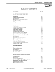
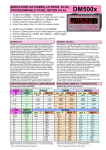
LM-3501 PRINT & APPLY SYSTEM
USER’S MANUAL
TABLE OF CONTENTS
SECTION
PAGE
1. APPLICATOR OVERVIEW
Introduction
General Printer Specifications
Inventory List
Print & Apply Component Description
User Responsibility
Safety
1-01
1-02
1-03
1-04
1-05
1-05
2. SETUP AND OPERATION
Web Routing
Thermal Print Head Label Loading
Thermal Ribbon Loading
Label Sensor Adjustment
Take Up Unit Assembly
Clutch Assembly Adjustment
Operator Interface Terminal
Accessory Connector Panel
T-50 Photo Eye
Air assist tube
T-150 Mounting Stand (optional)
T-stand adjustment
Tamp Unit Operation
Tamp Flow Control Adjustment
Optional Adjacent Panel Labeler (APL)
Optional Corner Wrap
2-01
2-03
2-03
2-03
2-04
2-05
2-06
2-07
2-07.5
2-08
2-09
2-10
2-11
2-12
2-13
2-14
3. CONTROL BOX
Programming
Quick Reference Chart
Key Definitions
Set Up Of Key Features
Description of I/O
3-01
3-05
3-15
3-16
3-20
4. CLEANING & MAINTENANCE
Troubleshooting
Fault Codes
Cleaning of the Print Head
Cleaning the Platen, Demand Plate and Rollers
Replacing the Print Head Power Fuse
Maintaining The Air Slide
Replacing Main Power Fuse
Page 1
Made in the U.S.A.
© 2003 MMI Automated Systems
4-01
4-02
4-03
4-03
4-03
4-04
4-05
12/23/03 Model LM-3501
LM-3501 PRINT & APPLY SYSTEM
USERS MANUAL
SECTION 1
APPLICATOR OVERVIEW
Introduction
General Printer Specifications
Inventory List
Print & Apply Component Description
User Responsibility
Safety
Page 2
Made in the U.S.A.
© 2003 MMI Automated Systems
1-01
1-02
1-03
1-04
1-05
1-05
12/23/03 Model LM-3501
LM-3501 PRINT & APPLY SYSTEM
USER’S MANUAL
LABEL MILL 3501
THERMAL PRINTER/APPLICATOR SYSTEM
INTRODUCTION
The Label-Mill 3501 is a state of the art THERMAL PRINTER & APPLICATOR SYSTEM created with
maximum flexibility for your AUTOMATIC LABELING NEEDS. The unit will print and apply high quality labels and
bar codes to your product at print speeds up to 10”/sec. and apply at speeds up to 80 labels/min.
OPERATION
The standard configuration is External Computer Mode. The configuration allows label formats to be sent to
the standard Centronics Parallel Interface Port, or serial port, on the Printer/Applicator. Once the format is
downloaded to the Printer Job Buffer, the system 3501 can print and apply as normal. Standard industry label
software packages can be used in conjunction with a PC to design and load label design.
1-01
Page 3
Made in the U.S.A.
© 2003 MMI Automated Systems
12/23/03 Model LM-3501
LM-3501 PRINT & APPLY SYSTEM
USERS MANUAL
SPECIFICATIONS
PRINT SPEED
Up to 10”/second and approx. 80 labels/min.
(Varies depending on label and product size.)
BAR CODES
UPC-A, UPC-E, EAN-8,EAN-13, Code 39, Int. 2 of 5, Code 128, MSI 2
of 5, UPC Bookland, and CODABAR.
BAR CODE RATIOS
1:2, 1:2.5, 1:3 or individually programmable bar code widths
HUMAN READABLE FONTS
Eight fonts including OCR-A and OCR-B representation and an outline
font. American and European fonts. Upper case and lower case with
decendors plus memory available for custom fonts.
LABEL ROLL CAPACITY
12” Max. outside diameter wound on a 3” diameter core. Die cut waste
removed with a minimum of 1/8” separation between labels in running
direction.
LABEL SIZE
Minimum: 1” wide x ¾” long
Maximum: 7.2” wide x 14” long
MAXIMUM PRINT AREA
6.5” wide x 14” long
LABEL PLACEMENT
ACCURACY
Up to + or - 1/32” (1mm) when labels are produced to specifications
and product handling is controlled.
PRINTING METHOD
Thermal Transfer and Direct Thermal
Print application method…Standard Tamp, Optional Blow On and
Wipe On.
INTERFACE
Standard Centronics Parallel Port
Standard RS-232C Serial Port
INTERFACE SENSORS
Ribbon out
Product Sensor-Photo Eye-Limit Switch
PLC input
ELECTRICAL
115V AC/60 Hz-250 W idle, 600 W running.
AIR REQUIREMENT
80 p.s.i./3 cfm
SIZE
21” W x 28-1/4” L x 23-3/8” D
ENVIRONMENT
Operating Temp. 50-95 F (10-35 C)
15-85% RH. non-condensing
WEIGHT
60 lb. (with U-Arms)
*Options available
1-02
Page 4
Made in the U.S.A.
© 2003 MMI Automated Systems
12/23/03 Model LM-3501
LM-3501 PRINT & APPLY SYSTEM
USER’S MANUAL
INVENTORY LIST
QTY.
1
2
1
2
1
1
1
1
1
1
Description
Print & Apply Assembly
12-½” dia. Blue Plastic Spools w / Quick Release Collar
7-¾” dia. Blue Plastic Spool w / screws
½” - 13 bolts w / washers
Power Cord
Model 3500 Operators Manual
Extra Cardboard Ribbon Core
Product Switch (specified)
a. Manual Limit Switch (optional)
b. Photo Switch (optional)
Take-up Spool Clip
Head Cleaning Kit (optional) Part No. SA070
TOOLS REQUIRED FOR ASSEMBLY
:
3/32” ALLEN WRENCH
¾” WRENCH
1-1/8” WRENCH
1-03
Page 5
Made in the U.S.A.
© 2003 MMI Automated Systems
12/23/03 Model LM-3501
LM-3501 PRINT & APPLY SYSTEM
USERS MANUAL
COMPONENT DESCRIPTION
LABEL SPOOL
TAMP
CYLINDER
SPOOL LOCK
U-ARM
THERMAL
PRINTER
WEB GUIDE
ROLLERS
WEB TAKE-UP
SPOOL
1-04
Page 6
Made in the U.S.A.
© 2003 MMI Automated Systems
12/23/03 Model LM-3501
LM-3501 PRINT & APPLY SYSTEM
USER’S MANUAL
USER RESPONSIBILITY
This equipment will perform in conformity with the description thereof contained in this manual and accompanying
labels and / or inserts when installed, operated, maintained, and repaired in accordance with the instructions
provided. This equipment must be checked periodically. Defective equipment should not be used. Parts that are
broken, missing, plainly worn, distorted, or contaminated should be replaced immediately. Should such repair or
replacement become necessary, we recommend that a request for service advice be made.
This equipment or any of its parts should not be altered without the prior written approval of MMI Automated
Systems. The user of this equipment shall have the sole responsibility for any malfunctions which results from
improper use, faulty maintenance, damage, improper repair or alteration by anyone other than MMI Automated
Systems or a service facility designated by MMI Automated Systems.
SAFETY
Only qualified personnel should use this equipment.
Before installing, inspecting or servicing equipment, turn OFF all power and air controls at the source and lock out
in accordance with OSHA Standards.
Be sure all external electrically conductive parts are connected to a good electrical ground.
Never handle live electrical equipment with bare hands while standing in water, or while hands and feet are wet.
Dangerous electrical shock can result.
Whenever the equipment is unattended, turn off all control and power supply switches.
Keep equipment clean and in good operating condition. Promptly repair or replace all worn or damaged hoses,
cables or parts.
Do not make any repairs to equipment unless you are fully qualified.
This equipment contains fast moving parts, which may move without warning. Keep hands, loose hair and
clothes clear of machines at all times.
Never place hands or any other body parts under the label platen at any time.
This equipment uses compressed air. Proper care and maintenance must be taken when handling compressed
air and its components.
These precautions are further detailed and explained where specifically required in this manual.
! WARNING
READ AND UNDERSTAND THESE INSTRUCTIONS
Protect yourself and others. Be sure this information is read and understood by all operators.
ELECTRICAL SHOCK CAN KILL!
Do not touch live electrical parts with bare skin or work with gloves or wet clothing.
NOISE CAN DAMAGE HEARING!
Wear proper ear protection.
1-05
Page 7
Made in the U.S.A.
© 2003 MMI Automated Systems
12/23/03 Model LM-3501
LM-3501 PRINT & APPLY SYSTEM
USERS MANUAL
SECTION 2
SETUP AND OPERATION
Web Routing
Thermal Print Head Label Loading
Thermal Ribbon Loading
Label Sensor Adjustment
Take Up Unit Assembly
Clutch Assembly Adjustment
Operator Interface Terminal
Accessory Connector Panel
T-50 Photo Eye
Air Assist Tube
T-150 Mounting Stand (option)
T-stand adjustment
Tamp Unit Operation
Tamp Flow Control Adjustment
Optional Adjacent Panel Labeler (APL)
Optional Corner Wrap
Page 8
Made in the U.S.A.
© 2003 MMI Automated Systems
2-01
2-03
2-03
2-03
2-04
2-05
2-06
2-07
2-07.5
2-08
2-09
2-10
2-11
2-12
2-13
2-14
12/23/03 Model LM-3501
LM-3501 PRINT & APPLY SYSTEM
USER’S MANUAL
WEB ROUTING
Step
Operation
1
Load web onto label storage spool (A) so it unloads in a clockwise direction. (refer to pg.
2-2)
Feed the web to the left and below roller guide (B), to the right of roller (C) and to the
left and below roller guide (D).
Feed the web into the thermal printer. (for a detailed description of thermal printer
routing see page 2-3)
Finish the process by loading the waste backing paper onto the web take up spool (E).
The take up spool rotates in a clockwise direction.
Adjust the (2) plastic web guide clips so the web is guided straight and even. Make sure
clips do not bind the web.
2
3
4
5
*For a detailed illustration of this procedure, see Figure 2-1 below.
FIGURE 2-1
/$
(/ 0
//
,
%
@
,
00
$ < 7 20$ 7 (
'
6
6
(0
@
(B)
%
6
7
0)
*
(A)
(C)
(E)
(D)
2-01
Page 9
Made in the U.S.A.
© 2003 MMI Automated Systems
12/23/03 Model LM-3501
LM-3501 PRINT & APPLY SYSTEM
USERS MANUAL
WEB ROUTING
SPOOL LOCK
6
0
(
7
6
(A)
0
)
*
@
6
'(
7
00
$0 2 7 < $ ,
%
@
(C)
(B)
(E)
(D)
SPOOL LOCK
SPOOL LOCK REMOVAL: To remove the label storage spool (A), turn the spool lock counterclockwise until you
reach a stop. The spool will now slide off. To secure the spool, simply turn the spool lock clockwise until snug. DO
NOT over tighten!
2-02
Page 10
Made in the U.S.A.
© 2003 MMI Automated Systems
12/23/03 Model LM-3501
LM-3501 PRINT & APPLY SYSTEM
USER’S MANUAL
LOADING THERMAL PRINT HEAD
REFER TO PRINTER MANUAL
LABEL & RIBBON ROUTING
REFER TO PRINTER MANUAL
THERMAL RIBBON LOADING
REFER TO PRINTER MANUAL
NOTE: The printer will not operate unless the front cover is in the fully closed position. For your
continued safety, do not override the front cover interlock switch.
LABEL SENSOR ADJUSTMENT
REFER TO PRINTER MANUAL
2-03
Page 11
Made in the U.S.A.
© 2003 MMI Automated Systems
12/23/03 Model LM-3501
LM-3501 PRINT & APPLY SYSTEM
USERS MANUAL
TAKE-UP UNIT ASSEMBLY
The Take-Up Assembly is
located on the backside of the
main panel. To adjust the
clutch, the side panels must be
removed to gain access. To
remove the Clutch Assembly,
you must first remove the Web
Take-Up Spool. The mounting
bolts for the Take-Up
Assembly can be found directly
behind the plastic spool.
WARNING!!! Be sure power is
off before performing any
service.
TAKE-UP
ASSEMBLY
2-04
Page 12
Made in the U.S.A.
© 2003 MMI Automated Systems
12/23/03 Model LM-3501
LM-3501 PRINT & APPLY SYSTEM
USER’S MANUAL
CLUTCH ADJUSTMENT
(A)
(B)
(C)
(D)
(E)
(F)
(G)
(H)
DRIVE DOG
SHAFT WHEEL
FRICTION DISC
PRESSURE PLATE
THRUST BEARING
PRESSURE SPRING
TENSION ADJ. COLLAR
SHAFT LOCK COLLAR
To increase waste web tension, move the Tension Adjustment Collar (G) 1/32” toward the motor. To reduce web
tension, move the Tension Adjustment Collar (G) 1/32” toward the spool.
CAUTION…Too much web tension may cause web breakage, print drifting, or premature failure of the TakeUp Assembly.
.
2-05
Page 13
Made in the U.S.A.
© 2003 MMI Automated Systems
12/23/03 Model LM-3501
LM-3501 PRINT & APPLY SYSTEM
USERS MANUAL
OPERATOR INTERFACE TERMINAL
LCD
OPERATOR
INTERFAC
MAIN POWER
2-06
Page 14
Made in the U.S.A.
© 2003 MMI Automated Systems
12/23/03 Model LM-3501
LM-3501 PRINT & APPLY SYSTEM
USER’S MANUAL
ACCESSORY CONNECTOR
LOCATED ON THE REAR PANEL OF THE OPERATOR INTERFACE TERMINAL
2-07
Page 15
Made in the U.S.A.
© 2003 MMI Automated Systems
12/23/03 Model LM-3501
LM-3501 PRINT & APPLY SYSTEM
USERS MANUAL
T-50 PHOTO EYE
2-07.5
Page 16
Made in the U.S.A.
© 2003 MMI Automated Systems
12/23/03 Model LM-3501
LM-3501 PRINT & APPLY SYSTEM
USER’S MANUAL
AIR ASSIST TUBE
The Air Assist Tube must be adjusted to
clear the trailing edge of the printed labels
and the Label Platen. An adjustment screw
is used to adjust the position of the air
holes in relation to the labels. An angle of
45 degrees is required.
One slot is provided to make the
appropriate adjustments desired.
.
Label Platen
Air Assist
Tube
Airflow
Blow tube
mounting
bracket
Adjustment
screw
Clamp screw
2-08
Page 17
Made in the U.S.A.
© 2003 MMI Automated Systems
12/23/03 Model LM-3501
LM-3501 PRINT & APPLY SYSTEM
USERS MANUAL
OPTIONAL T-150 MOUNTING STAND
2-09
Page 18
Made in the U.S.A.
© 2003 MMI Automated Systems
12/23/03 Model LM-3501
LM-3501 PRINT & APPLY SYSTEM
USER’S MANUAL
T-STAND ADJUSTMENT
Column Crank
Control Mounting
Arm
Column Lock
2-10
Page 19
Made in the U.S.A.
© 2003 MMI Automated Systems
12/23/03 Model LM-3501
LM-3501 PRINT & APPLY SYSTEM
USERS MANUAL
TAMP UNIT OPERATION
•
Tamp Duration
Tamp duration is used to provide an on timer for the solenoid valve on the main tamp cylinder. The delay on
standard versions can be from 0 to 30.000 seconds in 1/1000 of a second accuracy. This allows for easy
change over from one product height to another without physically changing the height of the unit. It also
allows for precise adjustments of how close the tamp head comes to the product. (refer to page 3-08)
There is flow control adjustment for the valves. It may be necessary to adjust the flow rate on the tamp solenoid
for optimum performance after installation. The adjustment is performed as shown below. They are set at the
factory. The regulators on the vacuum, air assist, and flag valves are for increasing or decreasing the air pressure
as necessary for proper operation. Note: Flag Regulator not shown below – only supplied with flag applicators.
Vacuum
Pump
Flow Control (B)
Flow Control (A)
Vacuum
regulator
Air assist
regulator
2-11
Page 20
Made in the U.S.A.
© 2003 MMI Automated Systems
12/23/03 Model LM-3501
LM-3501 PRINT & APPLY SYSTEM
USER’S MANUAL
TAMP FLOW CONTROL ADJUSTMENT
Regulator Adjustment: Clockwise - Increase pressure
Counterclockwise - Decrease pressure
MAIN AIR REGULATOR
Controls maximum air pressure available to entire applicator. Should be set between 40 and 80 PSI.
FLAG REGULATOR
The flag regulator is used to adjust the pressure that the flag jaws apply to the label as it is applied.
VACUUM REGULATOR (only used on the flag and tamp applicator system)
The vacuum regulator is used to control the vacuum that is used to hold the label to the flag jaws or the tamp pad.
AIR ASSIST REGULATOR
The air assist regulator is used to change the pressure that is applied to the blow tube. The blow tube is below
the front edge of the peeler plate and is used to help “push” the label onto the bottom of the tamp pad or the flag
jaws.
FLOW CONTROLS (tamp and flag applications)
Control A: This is used to adjust the pressure that controls the tamp cylinder in the upward direction.
Control B: Controls the tamp cylinder in the downward direction.
Page 21
Made in the U.S.A.
© 2003 MMI Automated Systems
12/23/03 Model LM-3501
LM-3501 PRINT & APPLY SYSTEM
USERS MANUAL
2-12
Page 22
Made in the U.S.A.
© 2003 MMI Automated Systems
12/23/03 Model LM-3501
LM-3501 PRINT & APPLY SYSTEM
USER’S MANUAL
OPTIONAL ADJACENT PANEL LABELER (APL)
2-13
Page 23
Made in the U.S.A.
© 2003 MMI Automated Systems
12/23/03 Model LM-3501
LM-3501 PRINT & APPLY SYSTEM
USERS MANUAL
OPTIONAL CORNER WRAP
2-14
Page 24
Made in the U.S.A.
© 2003 MMI Automated Systems
12/23/03 Model LM-3501
LM-3501 PRINT & APPLY SYSTEM
USER’S MANUAL
OPTIONAL SIDEWINDER
2-15
Page 25
Made in the U.S.A.
© 2003 MMI Automated Systems
12/23/03 Model LM-3501
LM-3501 PRINT & APPLY SYSTEM
USERS MANUAL
SECTION 3
CONTROL BOX
Programming
Quick Reference Chart
Key Definitions
Set Up of Key Features & Quick Start
Description of I/O
Page 26
Made in the U.S.A.
© 2003 MMI Automated Systems
3-01
3-05
3-15
3-16
3-21
12/23/03 Model LM-3501
LM-3501 PRINT & APPLY SYSTEM
USER’S MANUAL
PROGRAMMING
All programming is performed via the keypad and display as shown on page 2-6. All programmed settings are
battery backed in nonvolatile memory and are not lost when the unit is powered off.
Upon power up of the control, the screen will display MODEL NUMBER & REVISION. After this, the screen will
now display INITIALIZING. The final screen in the wake-up will display the counter, TOTAL XXXXXX BATCH
XXXXXX.
•
KEY FUNCTIONS:
UP - DOWN ARROW KEYS ARE USED TO:
1.
2.
3.
4.
Scroll up & down through the primary menu “PROGRAM BLOCKS” (Header name)
Scroll sub menus inside of “PROGRAM BLOCKS” (top line of display while IN a “PROGRAM BLOCKS”)
Scroll data selection / options (bottom line of display after entering the selected “PROGRAM BLOCKS”)
Select different display views while in the “RUN” mode.
“ENT” ENTER KEY IS USED TO:
1. Access or “Enter” the selected “PROGRAM BLOCK” (example PRODUCT SENSOR or TAMP SETUP)
2. Access or “Enter” the data selection / options line (bottom line of display) of the “PROGRAM BLOCK” Sub
Menus
3. Store the selected data and return to the Sub Menu of the “PROGRAM BLOCK” (top line of display)
Note that the carrot (>), on the left-hand side of the display, will move line to line (up / down) to indicate what line
you are currently in.
“PROG” PROGRAM KEY IS USED TO:
1.
2.
3.
4.
Enter Main program menu
Exit primary and secondary menus
Back out of the program menu one block at a time until you completely exit the program menu.
Exit a primary or secondary menu WITHOUT changing the data. (PROG key will not SAVE changes)
START KEY:
Start key will initialize the application cycle.
STOP/CLEAR KEY:
1. Stop key will abort the cycle only when not in the program menu and disable the system. The system will be
enabled only after the key is pressed again.
2. Clear key will delete stored values while in the edit mode.
HOT KEY:
The Hot Key is used while in the primary program block to fast forward to the desired program block. The number
located in the upper left-hand corner of the primary Program Block (0-9) identifies the Hot Key. For example, by
depressing the “4” key you will automatically advance to the Program Block “Counters”.
3-01
Page 27
Made in the U.S.A.
© 2003 MMI Automated Systems
12/23/03 Model LM-3501
LM-3501 PRINT & APPLY SYSTEM
USERS MANUAL
• PASS NUMBER
The PASS NUMBER is used to lock the menus of the control at (4) different levels. This option is used to prevent
unauthorized access to variable data. When shipped from the factory, the pass number is set to 0000 and NO
MENUS are locked. If a different pass number is entered, this number MUST BE MEMORIZED to be able to
access the settings in the controller at a later time.
• #1 PRODUCT SENSOR
This is an external device that when “activated” starts the application cycle.
PROGRAMMABLE BLOCKS:
Product Delay - delays the application of the label (x) seconds after the sensor has been activated **
Sensor Type - used to designate the type of product sensor used, Normally open is the standard
Sensor Trigger - designates whether the product sensor is activated at the leading or trailing edge of the
product.
Multiple Feed - how many labels are applied to one product with one signal (reset when signal is toggled)
Interval Delay - amount of time in seconds between multiple fed labels Note: only active if quantity 2 or higher
** Note the product delay feature will not work when the “Conveyor Lock” feature is activated, use TRIGGER
DISTANCE.
• #2 TAMP SET UP
This is used to adjust the different variables related to the tamp cycle.
PROGRAMMABLE BLOCKS:
Tamp duration - used to adjust the time that the tamp cylinder valve is actuated. (00.000 to 30.000)
Flag duration - used to adjust the time the flag jaws are held open after label application.(00.00 to 99.99)
Head up limit switch – type: normally open-standard, normally closed, none
Head up Dbounce – Debounce is used to allow time for the tamp cylinder to settle on return. (00.00 to 01.00)
Vacuum Release – Used to release label when tamping on light products.
Vacuum Delay On – Used to reduce label flutter when feeding large labels while tamping.
Tamp Sync Logic – Used to interface external equipment in relationship to the tamp cycle.
Air Assist DLY - Used to delay the air assist from turning off after feeding the label. (00.00 to 01.00)
• #3 TAKEUP
This is used to delay the start and stop of the take up motor.
PROGRAMMABLE BLOCKS:
Start delay – delays (x) seconds after start print before starting take up motor.
Stop delay – take up runs (x) seconds after end print signal is received from printer.
Jog take up – press the ENT key to jog the take up motor.
Note: If acceleration is set too low (Quick) following errors may occur.
3-02
Page 28
Made in the U.S.A.
© 2003 MMI Automated Systems
12/23/03 Model LM-3501
LM-3501 PRINT & APPLY SYSTEM
USER’S MANUAL
• #4 COUNTERS
Used to reset and set the internal counters of the control.
PROGRAMMABLE BLOCKS:
Total counter - resets the total counter to zero.
Batch counter - resets the batch counter to zero.
Batch counter set - sets the total number of labels to be applied in 1 batch.
Life counter - displays the total number of controller cycles, can not be reset.
(Note that when the batch counter expires the batch done output is activated.)
• #5 PRINT TYPE
The print type command is used to activate the print repeat cycle in the supplied print engine (Sato only). This
feature will continue to print the last label in the buffer after the buffer count has expired.
PROGRAMMABLE BLOCKS:
Print Repeat– turn repeat print option ON or OFF
• #6 ENCODER
Provides a more consistent way to apply labels to a product. With this option a distance from the trigger point can
be set at which the label is to be applied. Note: optional encoder must be used with this feature.
PROGRAMMABLE BLOCKS:
Encoder - used to turn the encoder option on or off.
Enc Override – Allows fine-tuning of the ratio of applicator speed to conveyor speed.
Trigger Distance - used to apply the label a certain distance away from the trigger point.
Start Comp Dist – Start Compensation Distance used to compensate for variable speed applications.
Enc lines/inch - tells how many pulses the encoder will count with 1 inch of travel. (25 to 500 counts per inch)
3-03
Page 29
Made in the U.S.A.
© 2003 MMI Automated Systems
12/23/03 Model LM-3501
LM-3501 PRINT & APPLY SYSTEM
USERS MANUAL
• #7 CYCLE TYPE
Determines the application type and sequence in relation to the label.
PROGRAMMABLE BLOCKS:
Tamp cycle type - Before feed (standard), after feed, No tamp, changes tamp cycle in relation to label
feeding.
Blow label - turns the blow on option on or off. Note: In the “BLOW mode” a tamp cycle must also be enabled
and a tamp duration entered (program block #2 TAMP).
Variable data - on or off, When turned on the preprint port is activated, this allows a optional product trigger to
print the label, the second (standard) trigger would activate the tamp cycle only. This is used primarily with
variable data being gathered for example when the applicator is being interfaced with a scale.
• #8 NOT SUPPORTED
• #9 JOB STORAGE
Used to store frequently used settings pertaining to different labeling jobs.
PROGRAMMABLE BLOCKS:
Job store - stores settings for last job.
Job select - allows operator to select 1 of the optional 10 stored jobs.
Job delete - allows operator to delete a stored job.
• DEFAULT SETTINGS
This setting will return the controller to the default settings.
• I/O STATUS
Displays the status of the inputs and outputs.
Page 30
Made in the U.S.A.
© 2003 MMI Automated Systems
12/23/03 Model LM-3501
LM-3501 PRINT & APPLY SYSTEM
USER’S MANUAL
3-04
Page 31
Made in the U.S.A.
© 2003 MMI Automated Systems
12/23/03 Model LM-3501
LM-3501 PRINT & APPLY SYSTEM
USERS MANUAL
QUICK PROGRAMMING CHART
MODEL NUMBER
&
REVISION
LM MODEL 1501
INITIALIZING
UP AND DOWN ARROW
KEYS WILL SCROLL
THROUGH THE
PROGRAM BLOCKS
AND THE SUB MENUS
TOTAL 000000
BATCH 000000
PRESS
"PROG"
KEY
PASS NUMBER
PRESS "ENTER"
#1 PRODUCT SENSOR
PRESS "ENTER"
#2 TAMP SET UP
PRESS "ENTER"
#3 TAKEUP
PRESS "ENTER"
3-05
Page 32
Made in the U.S.A.
© 2003 MMI Automated Systems
12/23/03 Model LM-3501
LM-3501 PRINT & APPLY SYSTEM
USER’S MANUAL
#4 COUNTERS
PRESS "ENTER"
#5 PRINT TYPE
PRESS "ENTER"
#6 ENCODER
PRESS "ENTER"
#7 CYCLE TYPE
PRESS "ENTER"
#8 NOT SUPPORTED
PRESS "ENTER"
#9 JOB STORAGE
PRESS "ENTER"
DEFAULT SETTINGS
PRESS "ENTER"
I/O STATUS
PRESS "ENTER"
PRESS
"PROG"
KEY
3-06
Page 33
Made in the U.S.A.
© 2003 MMI Automated Systems
12/23/03 Model LM-3501
LM-3501 PRINT & APPLY SYSTEM
USERS MANUAL
MAIN DISPLAYS
PASS NUMBER
PRESS "ENTER"
>LOCK WHAT MENUS
23456789
>ENTER PASS #
0000
>CHANGE PASS #
NO
CHANGE PASS #
>YES 0000
>LOCK WHAT MENUS
ALL
>LOCK WHAT MENUS
5678
Note: When a pass
number
is used, all menus not
numbered are
automatically locked, as
well as the selected locked
menus.
3-07
Page 34
Made in the U.S.A.
© 2003 MMI Automated Systems
12/23/03 Model LM-3501
LM-3501 PRINT & APPLY SYSTEM
USER’S MANUAL
#1 PRODUCT SENSOR
PRESS "ENTER"
SENSOR TYPE
>DISABLED
>PRODUCT DELAY
00.000 SECONDS
>SENSOR TYPE
NORMALLY OPEN
SENSOR TYPE
>NORMALLY CLOSED
>SENSOR TRIGGER
LEADING EDGE
SENSOR TRIGGER
>TRAILING EDGE
>ON DEBOUNCE
00.000
USED TO FILTER FAULSE
TRIGGERING
>OFF DEBOUNCE
00.000
USED TO FILTER FAULSE
TRIGGERING
>MULTIPLE FEED
QUANTITY # 01
MULTIPLE FEED
>QUANTITY # 02
Range 01-10
ONLY ACTIVE
#02 OR LARGER
>INTERVAL DELAY
00.00 SECONDS
3-08
Page 35
Made in the U.S.A.
© 2003 MMI Automated Systems
12/23/03 Model LM-3501
LM-3501 PRINT & APPLY SYSTEM
USERS MANUAL
#2 TAMP SETUP
PRESS "ENTER"
>TAMP DURATION
00.000 SECONDS
>FLAG DURATION
00.00 SECONDS
HEAD UP SWITCH
>NORMALLY OPEN
>HEAD UP SWITCH
NORMALLY CLOSED
HEAD UP SWITCH
>NO TAMP SWITCH
>HEAD UP DBOUNCE
00.00
>VACUUM RELEASE
00.00
Note this time
can never be larger
then the tamp duration
>VACUUM DELAY ON
00.00
TAMP SYNC LOGIC
>NORMAL
TAMP SYNC LOGIC
>REVERSE
AIR ASSIST DLY
>00.00
3-09
Page 36
Made in the U.S.A.
© 2003 MMI Automated Systems
12/23/03 Model LM-3501
LM-3501 PRINT & APPLY SYSTEM
USER’S MANUAL
#3 TAKEUP
PRESS "ENTER"
>START DELAY
.000
STOP DELAY
>.000
JOG TAKE UP
>ENTER TO JOG
#4 COUNTERS
PRESS "ENTER"
>TOTAL CNT RESET
PRESS "ENTER"
ARE YOU SURE?
YES, PUSH "ENTER"
>BATCH CNT. RESET
PRESS "ENTER"
ARE YOU SURE?
YES, PUSH "ENTER"
>BATCH PRESET
SET 0000000
>LIFE COUNTER
0000000
3-10
Page 37
Made in the U.S.A.
© 2003 MMI Automated Systems
12/23/03 Model LM-3501
LM-3501 PRINT & APPLY SYSTEM
USERS MANUAL
#5 PRINT TYPE
PRESS "ENTER"
>PRINT REPEAT
OFF
PRINT REPEAT
>OFF
#6 ENCODER
PRESS "ENTER"
>ENCODER
ON
>ENC OVERRIDE %
150.0
ENCODER
>OFF
Range
50-150%
>TRIGGER DISTANCE
00.00
START COMP DIST
0.000
RANGE
0 - 5.000
ENC LINES/INCH
0025.0
RANGE
25-500
3-11
Page 38
Made in the U.S.A.
© 2003 MMI Automated Systems
12/23/03 Model LM-3501
LM-3501 PRINT & APPLY SYSTEM
USER’S MANUAL
#7 CYCLE TYPE
PRESS "ENTER"
TAMP CYCLE TYPE
NO TAMP
>TAMP CYCLE TYPE
BEFORE FEED
TAMP CYCLE TYPE
>AFTER FEED
>BLOW LABEL
OFF
BLOW LABEL
>ON
>VARIABLE DATA
OFF
VARIABLE DATA
>ON
#8 NOT SUPPORTED
PRESS "ENTER"
3-12
Page 39
Made in the U.S.A.
© 2003 MMI Automated Systems
12/23/03 Model LM-3501
LM-3501 PRINT & APPLY SYSTEM
USERS MANUAL
#9 JOB STORAGE
PRESS "ENTER"
>JOB STORE
PRESS "ENTER"
>JOB SELECT
PRESS "ENTER"
>JOB DELETE
PRESS "ENTER"
>STORE CURRENT
00
1-10
>SELECT JOB FROM
00
DELETE JOB
>00
Range 01-10 Jobs
Range 01-10 Jobs
ENTER: OVERWRITE
CLEAR: ABORT
ARE YOU SURE?
YES, PUSH "ENTER"
DELETE THE JOB?
YES, PRESS "ENTER"
ARE YOU SURE?
YES, PUSH "ENTER"
THE JOB SELECTED
IS EMPTY
SELECT JOB FROM
RANGE 1-10
DEFAULT SETTINGS
PRESS "ENTER"
SET DEFAULTS
CLEAR: 5 SECONDS
3-13
Page 40
Made in the U.S.A.
© 2003 MMI Automated Systems
12/23/03 Model LM-3501
LM-3501 PRINT & APPLY SYSTEM
USER’S MANUAL
I/O STATUS
PRESS "ENTER"
>I/O STATUS
STATUS PANEL
I/O STATUS
>STATUS PANEL
DISPLAY I/O
PRESS "ENTER"
I/O STATUS
>PORT X0
PORT X0
0 0 0 0 0 0 0 0
X P SI Y A F V T
0 0 0 0 0 0 0 0
I/O STATUS
>PORT X1
PORT X1
0 0 0 0 0 0 0 0
I/O STATUS
>PORT X2
PORT X2
0 0 0 0 0 0 0 0
I/O STATUS
>PORT Y0
PORT Y0
0 0 0 0 0 0 0 0
I/O STATUS
>PORT Y1
PORT Y1
0 0 0 0 0 0 0 0
I/O STATUS
>PORT Y2
PORT Y2
0 0 0 0 0 0 0 0
I/O Ports are numbered as follows
76543210
Ports are numbered from right to left.
3-14
Page 41
Made in the U.S.A.
© 2003 MMI Automated Systems
12/23/03 Model LM-3501
LM-3501 PRINT & APPLY SYSTEM
USERS MANUAL
KEY DEFINITIONS
•
ASYNCHRONOUS OPERATION – The term “ASYNCHRONOUS OPERATION” is used because the speed
of the printer applicator motor (label speed) does not necessarily match the speed of the product conveyor. In
other words their speed is set independently of one another and has NO interrelation. The 3501 can only be
configured in asynchronous operation.
•
SYNCHRONOUS OPERATION - The term “SYNCHRONOUS OPERATION” is used because the speed of
the applicator motor (label speed) is matched to the speed of the product conveyor. In order to accomplish
this, an encoder is used to monitor the speed and distance the product conveyor travels. In order for this
feature to function the “CONVEYOR LOCK” mode must be turned on. In synchronous operation, the
applicator motor is ELECTRONICALLY GEARED to the product conveyor. The 3501 can NOT be
configured in synchronous operation.
•
START COMPENSATION – Start compensation compensates for the reaction time of the Label Mill control
and start signal from the product switch. The purpose of start compensation is to maintain label placement on
a product that is traveling at different speeds. An example of this is a conveyor that accelerates on start up
and decelerates to a stop. At high speeds an uncompensated system would apply a label too late and the
label would be placed too far back on the product. Linear interpolation is used to correct this problem. The
start compensation corrects this error by adding an offset distance at LOW speeds, since it is not possible to
apply any correction at high speed. Note: Start compensation ONLY effects label placement on product.
•
ELECTRONIC GEARING – Electronic gearing is a function of the product encoder and the Label Mill control.
This is used to match the speed of the applicator to the product conveyor. Electronic gearing is similar to
mechanical gearing in that there is a gear ratio and the change of speed of one affects the speed of the other.
This feature is part of the Synchronous feed mode. In order for this to operate properly, the correct number of
lines per inch of product travel must be entered into the ENC LINES/INCH in menu #6.
•
ENCODER – AN ENCODER is a device that is used to monitor the speed of an external device like a product
conveyor. The reason this speed is monitored is to match the speed of the label applicator to the product
speed. An encoder uses “LINES or COUNTS” per revolution in order to track speed and distance. Note that
lines per revolution are also referred to as counts per revolution. These counts are feed into the LABEL MILL
control to be processed for the different features that require this feed back.
•
ENCODER OVERRIDE – This feature is used in conjunction with ELECTRONIC GEARING. This feature is
used to fine-tune the ratio of the applicator to the product conveyor.
•
TRIGGER DIST – TRIGGER DISTANCE is used in conjunction with the encoder feature. Trigger distance is
similar to product delay in that it is used to electronically move the placement of the label on the product.
When the encoder feature is used, the product delay feature is rendered inactive. Trigger distance will move
the label placement in inches (00.00).
•
PRODUCT DELAY is NOT used in conjunction with the encoder feature. Product delay is similar to trigger
distance in that it is used to electronically move the placement of the label on the product. Product delay will
move the label placement in time (00.000) seconds. Because the product delay feature utilizes time, the
speed of the product MUST remain constant. A product traveling at a higher velocity will travel further in a
given time, thus effecting the placement of the label.
3-15
Page 42
Made in the U.S.A.
© 2003 MMI Automated Systems
12/23/03 Model LM-3501
LM-3501 PRINT & APPLY SYSTEM
USER’S MANUAL
QUICK START
1.
2.
3.
4.
5.
6.
7.
8.
9.
10.
11.
12.
13.
14.
Inspect applicator system and verify all cables are installed properly.
Web system with labels.
Turn power switch on.
Press “PROG”
Press “9” and then the down arrow “DEFAULT SETTINGS” press ENTER
Hold “CLEAR” button down for 5 seconds
Press “2” key
Set tamp duration to 00.200
Configure “Head up limit switch” standard is “normally open”.
Press “7” key
Set tamp cycle to “before feed”.
Once manual set up is complete exit the programming menu by pressing the “PROG” key twice.
While in the display mode press the “START” key, this will cycle the applicator.
System is now ready for set up of advanced features and options.
SETUP OF KEY FEATURES
•
START COMP DIST – START COMPENSATION DISTANCE
1.
2.
3.
4.
5.
Set basic applicator up first, refer to quick setup
Set ENCODER to “ON”.
Set TRIGGER DIST to 00.00
Set ENCODER LINES PER INCH (refer to ENC LINES set up)
Start system and apply label at the fastest desired speed. (system should not exceed maximum rate of
applicator)
Move product switch or use TRIGGER DIST to register label to desired position. Keep trigger distance to a
minimum for best results.
Change speed of system and operate it at the lowest speed desired.
Measure the offset in label placement.
Enter the measured offset into the START COMP DIST.
Operate system at the same low speed again and check label offset.
Make the necessary adjustments to the START COMP DIST.
Test again, repeat if necessary until label is in proper registration.
System should now hold registration throughout speed range.
Turn back on any options that may have been disabled for setup of this particular feature.
6.
7.
8.
9.
10.
11.
12.
13.
14.
Note there will be some label drift if speed range is too great or top speed is out of range of applicator. There is
also the normal placement tolerance that will effect the accuracy of the system.
3-16
Page 43
Made in the U.S.A.
© 2003 MMI Automated Systems
12/23/03 Model LM-3501
LM-3501 PRINT & APPLY SYSTEM
USERS MANUAL
•
CALCULATING ENCODER LINES PER INCH (gearing)
There are two basic concepts utilized to interface the product ENCODER to the Label Mill control. One method
utilizes a wheel mounted directly to an encoder. This wheel rests on the belt surface and rotates when the belt
moves. The second method is to mechanically slave the encoder to the conveyor utilizing belts or a chain etc.
Note that lines per revolution are also referred to as counts per revolution. The following is only a small sample of
the many ways there is to couple an encoder to a product conveyor.
WHEEL - MOUNTED
1.
2.
3.
4.
5.
Check encoder to determine the number of lines per revolution.
Measure diameter of contact wheel.
Multiply diameter of wheel by Pi, this will give circumference.
Divide encoder lines per revolution by circumference, this will net lines per inch.
Enter this number into menu #6 “ENC LINES/INCH”, note that this number needs to be between 25 & 500.
EXAMPLE
1.
2.
3.
4.
5.
Encoder lines per revolution “1000”.
Contact wheel diameter “6.00”.
6.00 x 3.14 = 18.84”
1000 / 18.84 = 53.1 (rounding number to the 10th)
Enter 53.1 into “ENC LINES/INCH”
DIRECT DRIVE
1.
2.
3.
4.
5.
6.
7.
Check encoder to determine the number of lines per revolution.
Determine the gear ratio of the encoder to the conveyor
Measure diameter of conveyor drive wheel.
Multiply diameter of wheel by Pi, this will give circumference.
Divide encoder lines per revolution by circumference, this will net lines per inch of wheel.
Multiply this number by the gear ratio, this will net lines per inch
Enter this number into menu #6 “ENC LINES/INCH”, note that this number needs to be between 25 & 500.
EXAMPLE
1.
2.
3.
4.
5.
6.
7.
Encoder lines per revolution “1000”.
Gear ratio is 2 to 1.
Conveyor drive wheel diameter “6.00”.
6.00 x 3.14 = 18.84”
1000 / 18.84 = 53.079
53.079 x 2 = 106.2 (rounding number to the 10th)
Enter 106.2 into “ENC LINES/INCH”
3-17
Page 44
Made in the U.S.A.
© 2003 MMI Automated Systems
12/23/03 Model LM-3501
LM-3501 PRINT & APPLY SYSTEM
USER’S MANUAL
•
TRIGGER DIST – TRIGGER DISTANCE
TRIGGER DISTANCE is used in conjunction with the encoder feature. Trigger distance is similar to product delay
in that it is used to electronically move the placement of the label on the product. When the encoder feature is
used, the product delay feature is rendered inactive. Trigger distance will move the label placement in inches
(00.00).
1. Set basic applicator up first, refer to quick setup
2. Ensure that the applicator is operating properly before starting this procedure.
3. This feature requires the use of an encoder. The appropriate encoder features should be setup prior to this
feature.
4. Set ENCODER to “ON”.
5. Set ENODER LINES “XXXX.X” Refer to CALCULATING ENCODER LINES PER INCH section.
6. Set TRIGGER DIST to 00.00
7. Start system and apply label at the desired speed.
8. Check the placement of the label on the product.
9. Measure the OFFSET of the label placement. Note: A label CAN NOT be advanced on the product ONLY
moved “back” since the applicator can only delay the product signal.
10. Apply the measured offset to the TRIGGER DISTANCE or if too great it may be necessary to physically move
the product switch. Keep trigger distances to a minimum for best results.
11. Operate system again and measure offset.
12. Enter the measured offset, IF ANY, into the TRIGGER DISTANCE.
13. Test again, repeat if necessary until label is in proper registration.
14. Turn back on any options that may have been disabled for setup of this particular feature.
•
PRODUCT DELAY
PRODUCT DELAY is NOT used in conjunction with the encoder feature. Product delay is similar to trigger
distance in that it is used to electronically move the placement of the label on the product. Product delay will move
the label placement in time (00.000). Because the product delay feature utilizes time, the speed of the product
MUST be constant and consistent.
1. Set basic applicator up first, refer to quick setup
2. Ensure that applicator is operating properly before starting this procedure.
3. This feature requires the use of an encoder. The appropriate encoder features should be setup prior to this
feature.
4. Set ENCODER to “OFF”.
5. Set CONVEYOR LOCK to “OFF” if in ASYNCHRONOUS operation.
6. If in SYNCHRONOUS operation PRODUCT DELAY WILL NOT WORK
7. Set Product delay to 00.000
8. Start system and apply label at the desired speed.
9. Check the placement of the label on the product.
10. Measure the OFFSET of the label placement. Note: A label CAN NOT be advanced on the product ONLY
moved “back” since the applicator can only delay the product signal.
11. Apply a small delay to the product delay or if too great, it may be necessary to physically move the product
switch. Keep product delays to a minimum for best results.
12. Operate system again and measure offset.
13. Apply a small delay to the product delay or reduce if too much.
14. Test again, repeat if necessary until label is in proper registration.
15. Turn back on any options that may have been disabled for setup of this particular feature
3-18
Page 45
Made in the U.S.A.
© 2003 MMI Automated Systems
12/23/03 Model LM-3501
LM-3501 PRINT & APPLY SYSTEM
USERS MANUAL
HOW TO SET UP AN ASYNCHRONOUS APPLICATION
•
“TAMP” WITHOUT A ENCODER
Determine the following and select it in the software
1.
2.
3.
4.
5.
Type of application mode. (Tamp) MENU #7
Tamp before or after feed (before feed is standard) MENU #7
Enter a value in the tamp duration (start with 00.20) MENU #2
Set head up limit switch, normally open is standard MENU #2
Use the product delay to “MOVE” the label on the product
The asynchronous application mode is used to apply labels to products that are either stationary or moving at a
constant speed when the label application is to take place.
•
“BLOW” WITHOUT AN ENCODER
Determine the following and select it in the software
1. Type of application mode. (Tamp) MENU #7
2. Tamp before or after feed (before feed is standard) MENU #7 (Note: Tamp before or after must be activated
for this option to operate)
3. BLOW LABEL must be turned “ON” MENU #7
4. Enter a value in the tamp duration (start with 00.10) MENU #2
5. Set head up limit switch to NO TAMP SWITCH MENU #2
6. Use the product delay to “MOVE” the label on the product
The asynchronous application mode is used to apply labels to products that are either stationary or moving at a
constant speed when the label application is to take place.
•
TAMP OR BLOW WITH A ENCODER
Determine the following and select it in the software
1.
2.
3.
4.
5.
6.
7.
Type of application mode. (Tamp, or Blow) (refer to above)
Tamp or blow before or after feed (before feed is standard)
Enter a value in the tamp duration (start with 00.200)
Turn encoder ON in menu #6
Encoder OVERRIDE is used to fine tune the GEARING RATIO between applicator and conveyor
Trigger distance is used to “MOVE” label on product (product delay is disabled)
Enter a Start Comp value. START Comp is used to compensate for label drift when speed of conveyor
changes. To calculate this refer to the section on “Start Compensation”
8. ENC LINES/INCH enter the proper “lines per inch” to match encoder output to conveyor speed. To calculate
“lines per inch”, refer to the section on Gearing.
3-19
Page 46
Made in the U.S.A.
© 2003 MMI Automated Systems
12/23/03 Model LM-3501
LM-3501 PRINT & APPLY SYSTEM
USER’S MANUAL
HOW TO SET UP AN VARIABLE DATA APPLICATION
•
“TAMP” WITHOUT AN ENCODER WITH TWO TRIGGER PHOTO EYES
Variable data application is utilized when the LM3501 is interfaced with a scale or other equipment that will be
transmitting a DIFFERENT label format to the applicator for every label that is applied. When this option is
activated, the use of the pre-print photo eye (option) is required. The pre-print photo eye will trigger the
printing of the label. The product photo eye (switch) will trigger the application (tamp) of the label. The reason for
two triggers is to improve the accuracy of the label placement when printing before applying.
General set up
1.
2.
3.
4.
The PRE-PRINT photo eye connects to the LIGHT BAR / AUX port.
The PRE-PRINT photo eye should be set to trigger on the leading edge of the product.
The PRE-PRINT photo eye should be set to trigger BEFORE the product switch.
The PRE-PRINT photo eye should be set to allow the printer enough time to print the format before the
product switch is activated.
5. The PRODUCT DELAY should be kept to a minimum.
Determine the following and select it in the software
•
“TAMP” WITHOUT AN ENCODER
1.
2.
3.
4.
5.
6.
7.
Type of application mode. (Tamp) MENU #7
Select “Tamp after feed” (before feed is not active) MENU #7
Select “Blow Label OFF” MENU #7
Select “Variable Data ON” MENU #7
Enter a value in the tamp duration (start with 00.20) MENU #2
Set head up limit switch, normally open is standard MENU #2
Use the product delay to “MOVE” the label on the product
The asynchronous application mode is used to apply labels to products that are either stationary or moving at a
constant speed when the label application is to take place.
•
“BLOW” WITHOUT AN ENCODER
Determine the following and select it in the software
1.
2.
3.
4.
5.
6.
7.
Type of application mode. (Tamp) MENU #7
Select “Tamp after feed” (before feed is not active) MENU #7
Select “Blow Label ON” MENU #7
Select “Variable Data ON” MENU #7
Enter a value in the tamp duration (start with 00.20) MENU #2
Set head up limit switch, “NO TAMP SWITCH” MENU #2
Use the product delay to “MOVE” the label on the product
The asynchronous application mode is used to apply labels to products that are either stationary or moving at a
constant speed when the label application is to take place.
3-19 - 1
Page 47
Made in the U.S.A.
© 2003 MMI Automated Systems
12/23/03 Model LM-3501
LM-3501 PRINT & APPLY SYSTEM
USERS MANUAL
•
TAMP WITH AN ENCODER
Determine the following and select it in the software
1.
2.
3.
4.
5.
6.
7.
8.
9.
10.
Type of application mode. (Tamp) MENU #7
Select “Tamp after feed” (before feed is not active) MENU #7
Select “Blow Label OFF” MENU #7
Select “Variable Data ON” MENU #7
Enter a value in the tamp duration (start with 00.20) MENU #2
Set head up limit switch, normally open is standard MENU #2
Turn encoder ON in menu #6
Encoder OVERRIDE is used to fine tune the GEARING RATIO between applicator and conveyor
Trigger distance is used to “MOVE” label on product (product delay is disabled)
Enter a Start Comp value. START Comp is used to compensate for label drift when speed of conveyor
changes. To calculate this refer to the section on “Start Compensation”
11. ENC LINES/INCH enter the proper “lines per inch” to match encoder output to conveyor speed. To calculate
“lines per inch”, refer to the section on Gearing.
•
BLOW WITH AN ENCODER
Determine the following and select it in the software
1.
2.
3.
4.
5.
6.
7.
8.
9.
10.
Type of application mode. (Tamp) MENU #7
Select “Tamp after feed” (before feed is not active) MENU #7
Select “Blow Label ON” MENU #7
Select “Variable Data ON” MENU #7
Enter a value in the tamp duration (start with 00.20) MENU #2
Set head up limit switch, “NO TAMP SWITCH” MENU #2
Turn encoder ON in menu #6
Encoder OVERRIDE is used to fine tune the GEARING RATIO between applicator and conveyor
Trigger distance is used to “MOVE” label on product (product delay is disabled)
Enter a Start Comp value. START Comp is used to compensate for label drift when speed of conveyor
changes. To calculate this refer to the section on “Start Compensation”
11. ENC LINES/INCH enter the proper “lines per inch” to match encoder output to conveyor speed. To calculate
“lines per inch”, refer to the section on Gearing.
3-19 - 2
Page 48
Made in the U.S.A.
© 2003 MMI Automated Systems
12/23/03 Model LM-3501
LM-3501 PRINT & APPLY SYSTEM
USER’S MANUAL
DESCRIPTION OF I/O
LEGEND
24V SEP:
24V OPT:
5V OPT:
OH:
OL:
24V OPTO INPUT WITH NO INTERNAL COMMON
24V OPTO INPUT WITH INTERNAL 24V COMMON
5V OPTO WITH EXTERNAL COMMON
HIGH CURRENT OUTPUT Rated @ 1amp
LOW CURRENT OUTPUT Rated @ 100 ma
All user inputs and output are “SINKING” type, except for the special isolated ground I/O. Example in order for a
status light to illuminate for “Run Status Ok” the light should be wired between pins #1 & #8 on the “Light Bar /
Aux.” Connector.
Status display legend.
X
SMART
TAMP
INPUTS
P
PRODUC
T
SENSOR
S
TAMP
SENSOR
Y
AUX OUT
#1
A
AIR ASSIST
SOL
OUTPUTS
F
V
FLAG
VACUUM
SOL
SOL
T
TAMP
SOL
When using the I/O status ports to verify if the inputs and outputs are on or off, the ports are numbered as from
right to left follows are as shown below: In this sample port Y2:0 , Y2:1 , Y2:3 , Y2:5 ,and Y2:7 are on.
I/O STATUS
>PORT Y1
PORT Y1
0 0 0 0 0 0 0 0
I/O STATUS
>PORT Y2
PORT Y2
0 0 0 0 0 0 0 0
PORT Y2
7 6 5 4 3 2 1 0
x o x o x o x x
3-20
Page 49
Made in the U.S.A.
© 2003 MMI Automated Systems
12/23/03 Model LM-3501
LM-3501 PRINT & APPLY SYSTEM
USERS MANUAL
SIGNAL NAMES
I/O
TYPE
MOTOR
PINS
P1
+24V
24C
O
O
+24V
24 COM
TAKE-UP
O
115 AC
12,13
VEL REF.
DRIVE +/MOTOR +/BRAKE RES.
DRIVE COM
DRIVE ENABLE
O
O
O
O
O
O
+/- 10
FET
FET
RES.
SHIELD
5V SINK
7,8
1,2
3,4
5,6
9
14
L SENSE
I
0-5V
TAMP
VACUUM
TAMP SW
FLAG
AIR ASSIST
SMART TAMP
AUX OUT (1)
OH
OH
I
OH
OH
I
OH
24V OPT
24V OPT
24V OPT
24V OPT
24V OPT
24V OPT
24V OPT
INHIBIT CYCLE
PRE-PRINT
LOW LABEL IN
REPEAT LAST LABEL
AUX IN (6)
AUX IN (7)
AUX IN (8)
AUX IN (9)
AUX IN (10)
AUX IN (11)
AUX IN (12)
AUX IN (13)
AUX IN (14)
INPLO (15)
INPLO (16)
INPLO (17)
INPLO COM
TAMP SYNC
RUN STATUS (OK)
BATCH DONE
AUX (5)
LOW RIBBON / LABEL
ERROR LITE
RIBBON OUT
AUX OUT (9)
AUX OUT (10)
AUX OUT (11)
AUX OUT (12)
I
I
I
I
I
I
I
I
I
I
I
I
I
I
I
I
I
OH
OH
OH
OL
OL
OL
OL
OL
OL
OL
OL
24V OPT
24V OPT
24V OPT
24V OPT
24V OPT
24V OPT
24V OPT
24V OPT
24V OPT
24V OPT
24V OPT
24V SEP
24V SEP
5V OPT
5V OPT
5V OPT
5V COM
24V OPT
24V OPT
24V OPT
24V OPT
24V OPT
24V OPT
24V OPT
24V OPT
24V OPT
24V OPT
24V OPT
PRINTER 5V
RIBBON LOW
ERROR
REPEAT PRINT
START PRINT
PRINT END
LABEL OUT
RIBBON OUT
PRINTER GRD
I
I
I
O
O
I
I
I
I
5V
5V OPT
5V OPT
5V OPT
5V OPT
5V OPT
5V OPT
5V OPT
GROUND
WEB
PINS
P2
LIGHT
PINS
P3
1
2
TRIG
PINS
P4
1
3
TAMP
PINS
P5
5
4
PRINTER
PINS
P6
AUX I/O
PINS
P9
13
25
1,2,3,4
1
2
3
6
7
8
9
9
10
11
12
11
12
14
15
16
17
18
19
20
13,14
9,10
21
22
23
24
1
2
3
8
7
8
3
4
5
6
4
5
6
7
1
2
3
4
5
6
7
8
9
3-21
Page 50
Made in the U.S.A.
© 2003 MMI Automated Systems
12/23/03 Model LM-3501
LM-3501 PRINT & APPLY SYSTEM
USER’S MANUAL
TAKE UP MOTOR CONNECTOR
9 PIN AMP
TAKE UP MOTOR NEUTRAL
TAKE UP MOTOR 1
TAKE UP MOTOR 2
P1
PIN #
1
2
3
4
5
6
7
8
9
ADDRESS
Y0,2
LIGHT BAR / AUXILIARY CONNECTOR
14 PIN AMP
P3
PIN #
+24 VOLTS
24V COMMON
AUX (5) HIGH CURRENT 24V OPTO
LOW RIBBON / LABEL HIGH CURRENT 24V OPTO
ERROR LIGHT HIGH CURRENT 24V OPTO
RIBBON OUT (8) HIGH CURRENT 24V OPTO
TAMP SYNC HIGH CURRENT 24V OPTO
RUN STATUS (OK) HIGH CUR 24V OPTO
INHIBIT 24V OPTO INTERNAL 24V COM
PRE-PRINT 24V OPTO INTERN 24V COM
LOW LABEL IN 24V OPTO INTERNAL 24V COM
LAST LABEL REPEAT IN 24V OPTO INTERNAL 24V COM
AUX IN 13 (+) NO INTERNAL COMMON
AUX IN 13 (-) NO INTERNAL COMMON
1
2
3
4
5
6
7
8
9
10
11
12
13
14
REMOTE TRIGGER CONNECTOR
(PRODUCT SWITCH)
4 PIN AMP
+24 VOLT
TRIGGER INPUT
24V COMMON
NO CONNECTION
P4
PIN #
1
2
3
4
INPUT /
OUTPUT
O
O
O
O
O
O
I
I
I
I
I
I
ADDRESS
Y2,0
Y2,1
Y2,2
Y2,3
Y1,5
Y1,6
X0,3
X0,4
X0,5
X0,6
X1,6
X1,6
ADDITIONAL
LOCATIONS SIGNAL IS
AVAILABLE
AUX I/O DB25
AUX I/O DB25
AUX I/O DB25
AUX I/O DB25
AUX I/O DB25
ADDRESS
X0,1
3-22
Page 51
Made in the U.S.A.
© 2003 MMI Automated Systems
12/23/03 Model LM-3501
LM-3501 PRINT & APPLY SYSTEM
USERS MANUAL
TAMP SOLENOIDS CONNECTOR
9 PIN AMP SMALL
TAMP SOL 24V
VACUUM SOL 24V
TAMP HEAD UP SW 24V
TAMP HEAD SW COM 24C
+24 VOLTS
FLAG SOL 24V
AIR ASSIST SOL 24V
SMART TAMP IN 24V INT. 24V COM
AUX 1 OUT 24V HIGH CURRENT
PRINT AND APPLY
CONNECTOR DB9
PRINTER +5V INPUT 5V OPTO
RIBBON LOW INPUT 5V OPTO
PRINTER ERROR INPUT 5V OPTO
PRINT REPEAT OUTPUT 5V OPTO
PRINT START OUTPUT 5V OPTO
PRINT END INPUT 5V OPTO
LABELS OUT INPUT 5V OPTO
RIBBON OUT INPUT 5V OPTO
PRINTER GROUND
P5
PIN #
1
2
3
4
5
6
7
8
9
INPUT /
OUTPUT
O
O
I
O
O
I
O
P6
PIN #
1
2
3
4
5
6
7
8
9
ADDRESS
Y1,0
Y1,1
X0,0
Y1,2
Y1,3
X0,2
Y1,4
ADDRESS
X2,0
X2,1
Y0,6
Y0,5
X2,2
X2,3
X2,4
AUX I/O
DB25 CONNECTOR
P9
PIN #
TAMP SYNC. HIGH CURRENT 24V OPTO
RUN STATUS (OK) HIGH CURRENT 24V OPTP
BATCH DONE HIGH CURRENT 24V OPTO
AUX OUT 9 LOW CURRENT 24V OPTO
AUX OUT 10 LOW CURRENT 24V OPTO
AUX OUT 11 LOW CURRENT 24V OPTO
AUX OUT 12 LOW CURRENT 24V OPTO
AUX OUT 5 HIGH CURRENT 24V OPTO
AUX IN 14 + NO INTERNAL COM
AUX IN 14 - NO INTERNAL COM
LOW LABEL IN 24V OPTO INTERNAL 24V COM
REPEAT LABEL IN 24V OPTO INTERNAL 24V COM
+24 VOLTS
AUX IN 6 24V OPTO INTERNAL 24V COM
AUX IN 7 24V OPTO INTERNAL 24V COM
AUX IN 8 24V OPTO INTERNAL 24V COM
AUX IN 9 24V OPTO INTERNAL 24V COM
AUX IN 10 24V OPTO INTERNAL 24V COM
AUX IN 11 24V OPTO INTERNAL 24V COM
AUX IN 12 24V OPTO INTERNAL 24V COM
5V AUX IN 1 5V OPTO EXTERNAL COM
5V AUX IN 2 5V OPTO EXTERNAL COM
5V AUX IN 3 5V OPTO EXTERNAL COM
5V AUX INPUT COMMON (TIE TO+5)
24V GROUND
1
2
3
4
5
6
7
8
9
10
11
12
13
14
15
16
17
18
19
20
21
22
23
24
25
INPUT /
OUTPUT
ADDRESS
O
O
O
O
O
O
O
O
I
I
I
I
Y1,5
Y1,6
Y1,7
Y2,4
Y2,5
Y2,6
Y2,7
Y2,0
X1,6
X1,6
X0,5
X0,6
I
I
I
I
I
I
I
I
I
I
X0,7
X1,0
X1,1
X1,2
X1,3
X1,4
X1,5
X2,5
X2,6
X2,7
ADDITIONAL
LOCATIONS SIGNAL
IS AVAILABLE
LIGHT BAR/AUX.
LIGHT BAR/AUX.
LIGHT BAR/AUX.
LIGHT BAR/AUX.
LIGHT BAR/AUX.
3-23
Page 52
Made in the U.S.A.
© 2003 MMI Automated Systems
12/23/03 Model LM-3501
LM-3501 PRINT & APPLY SYSTEM
USER’S MANUAL
COMM. 1 DB9
P7
PIN #
NO CONNECTION
RS232 XMIT
RS232 RCV
RCV+
RCVXMIT+
GND
XMITSHIELD
1
2
3
4
5
6
7
8
9
COMM. 2
DB9
NC
RS232 XMIT
RS232 RCV
RCV+
RCVXMIT+
GND
XMITSHIELD
P8
PIN #
1
2
3
4
5
6
7
8
9
SERVO CONNECTION IS NOT USED ON THE LM3501
SERVO
ENCODER DB9
1ENA
1ENB
VEL REF
Logic GND
+5
GND
Shield
Drive Enable
PIN 10
PIN #
1
2
3
4
5
6
7
8
9
CONVEYOR
ENCODER DB9
2ENA
2ENB
P11
PIN #
1
2
3
4
5
6
7
8
9
+5
GND
Shield
3-24
Page 53
Made in the U.S.A.
© 2003 MMI Automated Systems
12/23/03 Model LM-3501
LM-3501 PRINT & APPLY SYSTEM
USERS MANUAL
SECTION 4
CLEANING & MAINTENANCE
Troubleshooting
Fault Codes
Cleaning of the Print Head
Cleaning the Platen, Demand Plate and
Rollers
Replacing the Print Head Power Fuse
Maintaining the Air Slide
Replacing the Power Fuse
Page 54
Made in the U.S.A.
© 2003 MMI Automated Systems
4-01
4-02
4-03
4-03
4-03
4-04
4-05
12/23/03 Model LM-3501
LM-3501 PRINT & APPLY SYSTEM
USER’S MANUAL
TROUBLESHOOTING GUIDE
If the system malfunctions, it is necessary to determine where the problem exists in a normal sequence of
operation. The procedure of the unit is outlined in the left hand column of the table below to provide a systematic
approach to troubleshooting.
Problem
Possible Cause
Corrective Action
Unit will not turn on.
A. Blown Main Fuse
Check main power fuse and replace if
necessary as shown on page.
Check printer fuse
Air system will not operate.
A. No air pressure.
B. Plugged hose.
C. Faulty valve.
Check air supply and filter.
Fix or replace hose.
Consult factory.
Tamp will not operate.
A.
B.
C.
D.
E.
F.
No air
Plugged hose
Faulty valve
Cable
No tamp duration
Sticky cylinder
Check air supply and filter
Fix or replace hose
Consult factory
Check connection
Reference to page 2-11
Consult factory
Unit will not print or tamps
will not print
A.
B.
C.
D.
E.
F.
Unit off line
Incorrect label configuration
No label format downloaded
Wrong interface selected
Interface cable
Error on printer
Check printer cover limit switch
Check software
Check software
Check mode 3 or dip switches
Check connection
Check printer manual
Take-up unit does not turn.
A. Motor not running
B. Friction plate failure in clutch
C. Mechanical failure in clutch
Consult Factory
Consult Factory
Consult Factory
Waste web tension to loose.
A. Clutch tension too low.
Adjust clutch as shown on page 2-10.
Waste web breaks or
printing drifts on labels
A.
B.
C.
D.
E.
Adjust clutch as shown on page 2-10.
Re-web system as shown on page2-2.
Consult label mfg.
Consult factory.
Consult factory.
Clutch adjusted to tight.
Machine Webbed wrong.
Low quality webbing.
Friction plate failure in clutch.
Mechanical failure in clutch.
4-01
Page 55
Made in the U.S.A.
© 2003 MMI Automated Systems
12/23/03 Model LM-3501
LM-3501 PRINT & APPLY SYSTEM
USERS MANUAL
FAULT CODES
FAULT CODE
FAULT
REFER TO
Printer Cycle
A.
B.
C.
Printer Off Line
No Label Formats Loaded
Check Printer Interface Cable
Head Up
A.
B.
C.
D.
E.
F.
Tamp Cylinder Is Not Up
No Air
Faulty Valve
Flow Control Miss Adjusted
Miss Adjusted Reed Switch
Faulty Reed Switch
A.
B.
C.
D.
E.
F.
Tamp Cylinder Did Not Move
No Air
Faulty Valve
Flow Control Miss Adjusted
Faulty Reed Switch
Low Tamp Duration
Tamp duration is too low
Ribbon Out
A.
B.
Low Ribbon In Printer
Printer Out of Ribbon
Printer Manual
Label Out
A.
B.
Labels Out Of Printer
Printer Miss Adjusted
Printer Manual
Head Down
Printer Manual
Page 2-11 to 2-12
Light on reed switch should be on
when cylinder is up
Page 2-11 to 2-12
Page 3-02 and 3-08
4-02
Page 56
Made in the U.S.A.
© 2003 MMI Automated Systems
12/23/03 Model LM-3501
LM-3501 PRINT & APPLY SYSTEM
USER’S MANUAL
CLEANING THE PRINT HEAD
Refer to section 3-2 of the enclosed SATO Operator’s Manual for print head cleaning instructions or the
appropriate section in the ZEBRA or DATAMAX Operator’s Manual if so equipped.
CLEANING THE PLATEN, DEMAND PLATE, AND ROLLERS
Refer to section 3-3 of the enclosed SATO Operator’s Manual for print head cleaning instructions or the
appropriate section in the ZEBRA or DATAMAX Operator’s Manual if so equipped.
REPLACING THE PRINT HEAD POWER FUSE
Refer to section 3-5 of the enclosed SATO Operator’s Manual for print head cleaning instructions or the
appropriate section in the ZEBRA or DATAMAX Operator’s Manual if so equipped.
4-03
Page 57
Made in the U.S.A.
© 2003 MMI Automated Systems
12/23/03 Model LM-3501
LM-3501 PRINT & APPLY SYSTEM
USERS MANUAL
MAINTAINING THE AIR SLIDE
Very little maintenance is required to keep the Tamp Assembly’s air slide in good working condition. To
maintain the air slide, simply remove the air lines from the air slide and place 1-2 drops of any approved air motor
oil into the air inlets at least once a month. 1-2 drops of oil is also required for the incoming air supply.
WARNING!!! The main air supply must be shut off before you remove the air lines from the air slide.
Airline
4-04
Page 58
Made in the U.S.A.
© 2003 MMI Automated Systems
12/23/03 Model LM-3501
LM-3501 PRINT & APPLY SYSTEM
USER’S MANUAL
REPLACING THE MAIN POWER FUSE
The circuitry is protected from a current overload by GMA 10A a fast blow fuse. Should the applier fail to operate,
the condition of this fuse should be checked. If the fuse is open, the cause of the overload condition must be
determined and corrected prior to replacing the fuse. NEVER replace the fuse with one of a greater AMP rating.
The specified rating has been selected to prevent damage and/or injury.
ACTIONS TO REPLACE THE MAIN FUSE
1.
2.
3.
4.
5.
Set the main power switch to the OFF position.
Disconnect the AC power cable from the rear of the console.
Locate the fuse holder / power cord assembly.
Gently press down the fuse holder cover while pulling away from the console.
Replace with the spare fuse provided in the holder.
4-05
Page 59
Made in the U.S.A.
© 2003 MMI Automated Systems
12/23/03 Model LM-3501