1
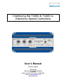
Interfacing the T4000 & T4400 to
Electronic Speed Controllers
User’s Manual
Revision: 020419
SELCO A/S
Betonvej 10 - DK-4000 Roskilde
Denmark
Phone: 45 7026 1122 - Fax: 45 7026 2522
e-mail: [email protected]
www.selco.com
Interfacing SELCO T4000 and T4400 to Electronic Speed Controllers
Table of Contents
1
2
3
Important Notice....................................................................................................4
Preface..................................................................................................................4
Pre-adjustment......................................................................................................5
3.1
SELCO T4000 Auto-Synchronizer.................................................................5
3.2
SELCO T4400 Load Sharer...........................................................................5
4 Commissioning and Test ......................................................................................5
5 Trouble Shooting...................................................................................................6
6 Barber Colman......................................................................................................8
6.1
DYN1 10504 ..................................................................................................8
6.1.1
Status .....................................................................................................8
6.1.2
Interfacing...............................................................................................8
6.1.3
Connection Diagram...............................................................................8
6.2
DYN1 10654/684/694 ....................................................................................9
6.2.1
Status .....................................................................................................9
6.2.2
Interfacing...............................................................................................9
6.2.3
Connection Diagram...............................................................................9
6.3
DYN1 10754 ................................................................................................10
6.3.1
Status ...................................................................................................10
6.3.2
Interfacing.............................................................................................10
6.3.3
Connection Diagram.............................................................................10
6.4
DYN1 10794 ................................................................................................11
6.4.1
Status ...................................................................................................11
6.4.2
Interfacing.............................................................................................11
6.4.3
Connection Diagram.............................................................................11
7 Cummins.............................................................................................................12
7.1
3037359.......................................................................................................12
7.1.1
Status ...................................................................................................12
7.1.2
Interfacing.............................................................................................12
7.1.3
Connection Diagram.............................................................................12
7.2
3062322 and 3062323.................................................................................13
7.2.1
Status ...................................................................................................13
7.2.2
Interfacing.............................................................................................13
7.2.3
Connection Diagram.............................................................................13
7.3
GSX15, QSK45 and QSK60 ........................................................................14
7.3.1
Status ...................................................................................................14
7.3.2
Interfacing.............................................................................................14
7.3.3
Connection Diagram.............................................................................14
8 Governors America Corp. (GAC) ........................................................................15
8.1
ESD-51xx, ESD-52xx and ESD-55xx ..........................................................15
8.1.1
Status ...................................................................................................15
8.1.2
Interfacing.............................................................................................15
8.1.3
Connection Diagram.............................................................................15
8.2
ESD-53xx.....................................................................................................16
8.2.1
Status ...................................................................................................16
8.2.2
Interfacing.............................................................................................16
8.2.3
Connection Diagram.............................................................................16
9 Heinzmann..........................................................................................................17
9.1
KG6 and KG16 ............................................................................................17
9.1.1
Status ...................................................................................................17
9.1.2
Interfacing.............................................................................................17
9.1.3
Connection Diagram.............................................................................17
10
Synchro-Start ..................................................................................................18
10.1
APECS 4x00 ............................................................................................18
Copyright © 2001 SELCO A/S
Page 2 of 22
Interfacing SELCO T4000 and T4400 to Electronic Speed Controllers
10.1.1 Status ...................................................................................................18
10.1.2 Interfacing.............................................................................................18
10.1.3 Connection Diagram.............................................................................18
11
Woodward .......................................................................................................19
11.1
2301A.......................................................................................................19
11.1.1 Status ...................................................................................................19
11.1.2 Interfacing.............................................................................................19
11.1.3 Connection Diagram.............................................................................19
11.2
2301A (with Load Sharer) ........................................................................20
11.2.1 Status ...................................................................................................20
11.2.2 Interfacing.............................................................................................20
11.2.3 Connection Diagram.............................................................................20
11.3
EPG..........................................................................................................21
11.3.1 Status ...................................................................................................21
11.3.2 Interfacing.............................................................................................21
11.3.3 Connection Diagram.............................................................................21
11.4
ST-125 .....................................................................................................22
11.4.1 Status ...................................................................................................22
11.4.2 Interfacing.............................................................................................22
11.4.3 Connection Diagram.............................................................................22
Copyright © 2001 SELCO A/S
Page 3 of 22
Interfacing SELCO T4000 and T4400 to Electronic Speed Controllers
1 Important Notice
The Variable out 14/16 adjustment on early versions of the T4400 delivered
before December 1, 2001 works opposite of what is described within this
document. On this early version the Variable Out 14/16 knob must be turned
clockwise to decreases the span of the output signal.
The Stability adjustment on early versions of the T4400 delivered before April
1, 2002 works opposite of what is described in this document. One this early
version the Stability knob must be turned clockwise to decreases stability.
2 Preface
This document describes the used of various brands and types of electronic speed
controllers together with the SELCO T4000 Auto-Synchronizer and the SELCO
T4400 Load Sharer.
The SELCO T4000 and SELCO T4400 are designed for direct control of the
electronic speed controller, thus no intermediate motorized or electronic
potentiometer is required. The direct control improves system speed as the relatively
slow ramped control signal is replaced by closed loop regulation with electronic
feedback and lead/lag compensation.
The schematic diagrams can also be used with the SELCO T4300, however one
should note that the output terminals numbers are not the same as on the SELCO
T4400.
Signal
SELCO T4400
SELCO T4300
Output reference
Terminal 15
Terminal 15
Non inverted Output
Terminal 16
Terminal 16
Inverted Output
Terminal 14
Terminal 26
Please note that the SELCO T4400 includes both integrated output and internal
frequency control (system frequency stabilisation). These features are not available
on the SELCO T4300.
Copyright © 2001 SELCO A/S
Page 4 of 22
Interfacing SELCO T4000 and T4400 to Electronic Speed Controllers
3 Pre-adjustment
3.1 SELCO T4000 Auto-Synchronizer
Phase Angle:
Stability:
Variable out. 22:
Set to tolerated phase angle for closure (e.g. point 6)
Set to point 5 for relatively high stability/low adjustment speed
Set to 1/3 of maximum for relatively high output voltage span
(relatively low resistance between terminal 22 and 21)
3.2 SELCO T4400 Load Sharer
Load Dev. %:
Diff. Frequency:
Stability:
Variable out. 14/16:
Set to mid point (0%)
Set to mid point (0%), also check terminal 29 and 30.
Set to point 7 for relatively high stability/low adjustment speed
Set to 4/5 of maximum for relatively high output voltage span
4 Commissioning and Test
1. Start up the generators one at a time. The generators must be running
without load (with the circuit breaker open). Adjust the speed/frequency
setting (Idle) on the speed controller to suit the required system frequency (50
or 60 Hz).
2. Shut down the generators and make sure that the generator AC outputs are
not live.
3. Verify that the connections for the voltage and current measurement of the
SELCO T4000 and T4400 are connected exactly as described on label
located on the top of the units. This is very important.
4. Connect the SELCO T4000 and T4400 according to the schematic diagram
included in this document.
5. Pre-adjust the SELCO T4000 and T4400 according to the above directions1.
6. Disconnect the T4000 CLOSE terminals (9 and 10) to avoid automatic closure
of the circuit breaker, which is practical during commissioning and test.
7. Start up the generators one at a time (again without load and the circuit
breaker open).
8. If necessary, readjust the speed/frequency setting (Idle) on the speed
controller to suit the required system frequency (50/60 Hz). The system
frequency might have shifted a little due to the impedance properties of the
T4400 output circuitry.
9. Reconnect the T4000 CLOSE terminals (9 and 10) to enable automatic
closure of the circuit breaker.
10. Start up the first generator and close the circuit breaker to connect it to the
common (dead) bus bar. Observe that synchronisation is necessary if the bus
bar is live (e.g. when paralleling with the grid or another source).
11. Verify that the system frequency is still correct. If not, return to step 5.
12. Start up the second generator and observe that automatic synchronization
and closure of the circuit breaker is performed as expected.
13. Verify that the engine speed and system frequency is stable (and that system
frequency is correct). If not, return to step 5.
14. Repeat step 9 to 10 for the remaining generators (if any).
15. Transfer some load to the parallel running generators and observe that any
moderate (but sudden) load inflictions do not cause instability or cyclic
1
Be sure to read the notes regarding modifications to the adjustments scheme of the T4400.
The notes are printed at beginning of this document.
Copyright © 2001 SELCO A/S
Page 5 of 22
Interfacing SELCO T4000 and T4400 to Electronic Speed Controllers
fluctuations in the engine speed/frequency. If so, increase the stability
settings (turn clockwise) on the SELCO T4400 load sharers. It might also be
necessary to decrease the strength of the voltage output signal (turn the
Variable Out 14/16 dial counter clockwise).
16. Remove some load from the parallel running generators and observe that any
moderate (but sudden) load release do not cause instability or cyclic
fluctuations in the engine speed/system frequency. If so, increase the stability
settings (turn clockwise) of the SELCO T4400 load sharers. It might also be
necessary to decrease the strength of the voltage output signal (turn the
Variable Out 14/16 dial counter clockwise).
17. Set the load level to about 90% of the capacity of generator number 1 (so that
each of the two generators is loaded 45%). Then activate the soft unload
function of the SELCO T4400 controlling generator number 2. Observe that
generator 2 is slowly unloaded (be careful not to overload generator number
1). You should get a de-loaded trip signal when the load passes beneath
approximately 2%.
18. Disable the soft unload function and observe that the load is slowly
transferred back to generator 2.
19. Remove the load, trip the generator circuit breakers one at a time and shut
down the generators.
5 Trouble Shooting
Q: The system becomes unstable when the SELCO T4000 is active.
A: Check the connection between the SELCO T4000 and T4400. Make sure that
the variable output (terminal 22) on the T4000 is connected to Sync. In.
(terminal 9) on the T4400. Also try to decrease the Variable out. 22 signal of
the T4000 (turn clockwise to increase resistance between terminal 22 and
21).
Q: The generator is shut down on over-speed during start-up.
A: The output signal from the T4400 is too strong. Reduce the output signal by
turning the Variable Out 14/16 counter clockwise.
Q: The load is generally unstable, even when the system is not loaded.
A: Check the reference signal of the T4400 (terminal 15). Instruments (e.g.
multimeters or scopes) attached between terminal 14/16 and 15 might disturb
the output signal.
Q: The system becomes unstable when load is transferred to/from the parallel
running generators.
A: Try to increase the Stability (turn clockwise) on all the SELCO T4400. Stability
is a trade-off between regulation speed and system stability.
Q: The load fluctuates after the other generator was unloaded.
A: Increase Stability (turn clockwise) on the T4400 units.
Q: The T4400 appears to react slowly to load fluctuations.
Copyright © 2001 SELCO A/S
Page 6 of 22
Interfacing SELCO T4000 and T4400 to Electronic Speed Controllers
A: Reduce stability or increase the response of the output signal (Turn Stability
counter-clockwise). However be careful not to make the system too sensitive.
Copyright © 2001 SELCO A/S
Page 7 of 22
Interfacing SELCO T4000 and T4400 to Electronic Speed Controllers
6 Barber Colman
6.1 DYN1 10504
6.1.1 Status
Assumed similar to Cummins 3037359
6.1.2 Interfacing
The auxiliary speed input (terminal 7) of the 10504 controller accepts a signal in the
range of +8 to 0 VDC. The output signal of the SELCO T4400 must be adapted in
order to fit this range. This is easily done using a voltage divider constructed from two
10 kOhm resistors connected between +8 VDC (terminal 6) and common (terminal ?)
on the 10504 controller. The midpoint of the voltage divider (+4 VDC) is then used as
a reference for the T4400, which will adapt it’s output range to +8 to 0 VDC (or just
about).
6.1.3
Connection Diagram
SELCO T4000 and T4400 with Barber Colman DYN1 10504
L1
L2
17
18
19
20
21
22
23
24
25
26
27
28
29
30
31
32
12
13
14
15
16
28
29
30
31
32
12
13
14
15
16
Please contact SELCO regarding connection to other electronic speed controllers. Signal adaption might differ between brand and mark.
L3
SELCO T4000
Auto-Synchroniser
1
2
3
4
5
6
7
8
9
10
11
C/B Close
C/B
17
18
19
20
21
22
23
24
25
26
27
SELCO T4400
Load Sharer
1
2
3
4
5
6
7
8
9
10
11
7
Diesel Engine
1
0
K
COM
G
1
0
K
6
Soft
Load/Unload
Barber Colman DYN1 10504
ACTUATOR
PICKUP
Copyright © 2001 SELCO A/S
ACTUATOR
Pickup
PICKUP
Actuator
Page 8 of 22
Interfacing SELCO T4000 and T4400 to Electronic Speed Controllers
6.2 DYN1 10654/684/694
6.2.1 Status
Assumed similar to Cummins 3037359
6.2.2 Interfacing
The auxiliary speed input (terminal 7) of the 10654/684/694 controller accepts a
signal in the range of +8 to 0 VDC. The output signal of the SELCO T4400 must be
adapted in order to fit this range. This is easily done using a voltage divider
constructed from two 10 kOhm resistors connected between +8 VDC (terminal 6) and
common (terminal ?) on the 10654/684/694 controller. The midpoint of the voltage
divider (+4 VDC) is then used as a reference for the T4400, which will adapt it’s
output range to +8 to 0 VDC (or just about).
6.2.3
Connection Diagram
SELCO T4000 and T4400 with Barber Colman DYN1 10654/684/694
L1
L2
17
18
19
20
21
22
23
24
25
26
27
28
29
30
31
32
12
13
14
15
16
28
29
30
31
32
12
13
14
15
16
Please contact SELCO regarding connection to other electronic speed controllers. Signal adaption might differ between brand and mark.
L3
SELCO T4000
Auto-Synchroniser
1
2
3
4
5
6
7
8
9
10
11
C/B Close
C/B
17
18
19
20
21
22
23
24
25
26
27
SELCO T4400
Load Sharer
1
2
3
4
5
6
7
8
9
10
11
7
Diesel Engine
1
0
K
COM
G
1
0
K
6
Soft
Load/Unload
Barber Colman DYN1 10654/684/694
ACTUATOR
PICKUP
Copyright © 2001 SELCO A/S
ACTUATOR
Pickup
PICKUP
Actuator
Page 9 of 22
Interfacing SELCO T4000 and T4400 to Electronic Speed Controllers
6.3 DYN1 10754
6.3.1 Status
Assumed similar to Cummins 3037359
6.3.2 Interfacing
The auxiliary speed input (terminal 7) of the 10754 controller accepts a signal in the
range of +8 to 0 VDC. The output signal of the SELCO T4400 must be adapted in
order to fit this range. This is easily done using a voltage divider constructed from two
10 kOhm resistors connected between +8 VDC (terminal 6) and common (terminal ?)
on the 10754 controller. The midpoint of the voltage divider (+4 VDC) is then used as
a reference for the T4400, which will adapt it’s output range to +8 to 0 VDC (or just
about).
6.3.3
Connection Diagram
SELCO T4000 and T4400 with Barber Colman DYN1 10754
L1
L2
17
18
19
20
21
22
23
24
25
26
27
28
29
30
31
32
12
13
14
15
16
28
29
30
31
32
12
13
14
15
16
Please contact SELCO regarding connection to other electronic speed controllers. Signal adaption might differ between brand and mark.
L3
SELCO T4000
Auto-Synchroniser
1
2
3
4
5
6
7
8
9
10
11
C/B Close
C/B
17
18
19
20
21
22
23
24
25
26
27
SELCO T4400
Load Sharer
1
2
3
4
5
6
7
8
9
10
11
7
Diesel Engine
1
0
K
COM
G
1
0
K
6
Soft
Load/Unload
Barber Colman DYN1 10754
ACTUATOR
PICKUP
Copyright © 2001 SELCO A/S
ACTUATOR
Pickup
PICKUP
Actuator
Page 10 of 22
Interfacing SELCO T4000 and T4400 to Electronic Speed Controllers
6.4 DYN1 10794
6.4.1 Status
Assumed similar to Cummins 3037359
6.4.2 Interfacing
The auxiliary speed input (terminal 9) of the 10794 controller accepts a signal in the
range of +8 to 0 VDC. The output signal of the SELCO T4400 must be adapted in
order to fit this range. This is easily done using a voltage divider constructed from two
10 kOhm resistors connected between +8 VDC (terminal 7) and common (terminal
11) on the 10794 controller. The midpoint of the voltage divider (+4 VDC) is then
used as a reference for the T4400, which will adapt it’s output range to +8 to 0 VDC
(or just about).
6.4.3
Connection Diagram
SELCO T4000 and T4400 with Barber Colman DYN1 10794
L1
L2
17
18
19
20
21
22
23
24
25
26
27
28
29
30
31
32
12
13
14
15
16
28
29
30
31
32
12
13
14
15
16
Please contact SELCO regarding connection to other electronic speed controllers. Signal adaption might differ between brand and mark.
L3
SELCO T4000
Auto-Synchroniser
1
2
3
4
5
6
7
8
9
10
11
C/B Close
C/B
17
18
19
20
21
22
23
24
25
26
27
SELCO T4400
Load Sharer
1
2
3
4
5
6
7
8
9
10
11
G
1
0
K
9
11
Diesel Engine
1
0
K
7
Soft
Load/Unload
Barber Colman DYN1 10794
ACTUATOR
PICKUP
Copyright © 2001 SELCO A/S
ACTUATOR
Pickup
PICKUP
Actuator
Page 11 of 22
Interfacing SELCO T4000 and T4400 to Electronic Speed Controllers
7 Cummins
7.1 3037359
7.1.1 Status
Confirmed by test.
7.1.2 Interfacing
The auxiliary speed input (terminal 9) of the 3037359 controller accepts a signal in
the range of +8 to 0 VDC. The output signal of the SELCO T4400 must be adapted in
order to fit this range. This is easily done using a voltage divider constructed from two
10 kOhm resistors connected between +8 VDC (terminal 7) and common (terminal
11) on the 3037359 controller. The midpoint of the voltage divider (+4 VDC) is then
used as a reference for the T4400, which will adapt it’s output range to +8 to 0 VDC
(or just about).
7.1.3
Connection Diagram
SELCO T4000 and T4400 with Cummins Controller 3037359
L1
L2
17
18
19
20
21
22
23
24
25
26
27
28
29
30
31
32
12
13
14
15
16
28
29
30
31
32
12
13
14
15
16
Please contact SELCO regarding connection to other electronic speed controllers. Signal adaption might differ between brand and mark.
L3
SELCO T4000
Auto-Synchroniser
1
2
3
4
5
6
7
8
9
10
11
C/B Close
C/B
17
18
19
20
21
22
23
24
25
26
27
SELCO T4400
Load Sharer
1
2
3
4
5
6
7
8
9
10
11
G
1
0
K
9
11
Diesel Engine
1
0
K
7
Soft
Load/Unload
Cummins Controller 3037359
ACTUATOR
PICKUP
Copyright © 2001 SELCO A/S
ACTUATOR
Pickup
PICKUP
EFC
Page 12 of 22
Interfacing SELCO T4000 and T4400 to Electronic Speed Controllers
7.2 3062322 and 3062323
7.2.1 Status
Assumed similar to Cummins 3037359 (however terminals are different)
7.2.2 Interfacing
The auxiliary speed input (terminal K/30) of the 3062322/3 controller accepts a signal
in the range of +7 to 0 VDC. The output signal of the SELCO T4400 must be adapted
in order to fit this range. This is easily done using a voltage divider constructed from
two 10 kOhm resistors connected between +7 VDC (terminal H/28) and common
(terminal F/12) on the 3062322/3 controller. The midpoint of the voltage divider (+3.5
VDC) is then used as a reference for the T4400, which will adapt it’s output range to
+7 to 0 VDC (or just about).
7.2.3
Connection Diagram
SELCO T4000 and T4400 with Cummins Controller 3062322 and 3062323
L1
L2
17
18
19
20
21
22
23
24
25
26
27
28
29
30
31
32
12
13
14
15
16
28
29
30
31
32
12
13
14
15
16
Please contact SELCO regarding connection to other electronic speed controllers. Signal adaption might differ between brand and mark.
L3
SELCO T4000
Auto-Synchroniser
1
2
3
4
5
6
7
8
9
10
11
C/B Close
C/B
17
18
19
20
21
22
23
24
25
26
27
SELCO T4400
Load Sharer
1
2
3
4
5
6
7
8
9
10
11
G
F/12
1
0
K
K/30
Diesel Engine
1
0
K
H/28
Soft
Load/Unload
Cummins Controller 3062322 and 3062323
ACTUATOR
PICKUP
Copyright © 2001 SELCO A/S
ACTUATOR
Pickup
PICKUP
EFC
Page 13 of 22
Interfacing SELCO T4000 and T4400 to Electronic Speed Controllers
7.3 GSX15, QSK45 and QSK60
7.3.1 Status
Confirmed by test.
7.3.2 Interfacing
The auxiliary speed bias input of the GSX and QSK controllers is accessible through
the ECM Connector 03. Connector 03 is a DB25 plug, so it is necessary to solder the
wires from the Load Sharer output directly to the pins of the DB25 plug.
The QSX and QSK controller can operate with a –2.5 to +2.5 VDC speed bias signal
(speed control signal). The +5 VDC reference signal (ECM pin 6) connects to T4400
terminal 15, while the 2,5 VDC speed bias signal (ECM pin 11) connects to T4400
terminal 16.
7.3.3
Connection Diagram
SELCO T4000 and T4400 with Cummins QSX15, QSK45 and QSK60
L1
L2
19
20
21
22
23
24
25
26
27
28
29
30
31
32
12
13
14
15
16
28
29
30
31
32
12
13
14
15
16
Please contact SELCO regarding connection to other electronic speed controllers. Signal adaption might differ between brand and mark.
18
Pin 6
17
Pin 11
L3
SELCO T4000
Auto-Synchroniser
1
2
3
4
5
6
7
8
9
10
11
C/B Close
C/B
17
18
19
20
21
22
23
24
25
26
27
SELCO T4400
Load Sharer
1
2
3
4
5
6
7
8
9
10
11
Soft
Load/Unload
G
Diesel Engine
ECM Connector 03 (DB25)
Cummins GSX15, QSK45 and QSK60
PICKUP
ACTUATOR
Copyright © 2001 SELCO A/S
PICKUP
Pickup
ACTUATOR
Actuator
Page 14 of 22
Interfacing SELCO T4000 and T4400 to Electronic Speed Controllers
8 Governors America Corp. (GAC)
8.1 ESD-51xx, ESD-52xx and ESD-55xx
8.1.1 Status
Confirmed by test.
8.1.2 Interfacing
The auxiliary speed input (AUX/N) of the ESD-51xx/52xx accepts a signal in the
range of +10 to 0 VDC. The output signal of the SELCO T4400 must be adapted in
order to fit this range. This is easily done using a voltage divider constructed from two
10 kOhm resistors connected between +10 VDC (terminal 10V/P) and battery minus
(terminal BATTERY-/E) on the GAC speed controller. The midpoint of the voltage
divider (+5 VDC) is then used as a reference for the T4400, which will adapt the
output range to +10 to 0 VDC (depending on the Variable Out 14/16 setting).
8.1.3
Connection Diagram
SELCO T4000 and T4400 with GAC ESD-51xx or 52xx
L1
L2
17
18
19
20
21
22
23
24
25
26
27
28
29
30
31
32
12
13
14
15
16
28
29
30
31
32
12
13
14
15
16
Please contact SELCO regarding connection to other electronic speed controllers. Signal adaption might differ between brand and mark.
L3
SELCO T4000
Auto-Synchroniser
1
2
3
4
5
6
7
8
9
10
11
C/B Close
C/B
17
18
19
20
21
22
23
24
25
26
27
SELCO T4400
Load Sharer
1
2
3
4
5
6
7
8
9
10
11
Soft
Load/Unload
1
0
K
E (BATT. -)
Diesel Engine
P (10V)
G
N (AUX)
1
0
K
GAC ESD-51xx or 52xx
ACTUATOR
PICKUP
Copyright © 2001 SELCO A/S
ACTUATOR
Pickup
PICKUP
Actuator
Page 15 of 22
Interfacing SELCO T4000 and T4400 to Electronic Speed Controllers
8.2 ESD-53xx
8.2.1 Status
Control scheme assumed similar to ESD-51xx/52xx (terminals different)
8.2.2 Interfacing
The auxiliary speed input (AUX/M) of the ESD-53xx accepts a signal in the range of
+10 to 0 VDC. The output signal of the SELCO T4400 must be adapted in order to fit
this range. This is easily done using a voltage divider constructed from two 10 kOhm
resistors connected between +10 VDC (terminal 10V/L) and battery minus (terminal
BATTERY-/C) on the GAC speed controller. The midpoint of the voltage divider (+5
VDC) is then used as a reference for the T4400, which will adapt the output range to
+10 to 0 VDC (depending on the Variable Out 14/16 setting).
8.2.3
Connection Diagram
SELCO T4000 and T4400 with GAC ESD-53xx
L1
L2
17
18
19
20
21
22
23
24
25
26
27
28
29
30
31
32
12
13
14
15
16
28
29
30
31
32
12
13
14
15
16
Please contact SELCO regarding connection to other electronic speed controllers. Signal adaption might differ between brand and mark.
L3
SELCO T4000
Auto-Synchroniser
1
2
3
4
5
6
7
8
9
10
11
C/B Close
C/B
17
18
19
20
21
22
23
24
25
26
27
SELCO T4400
Load Sharer
1
2
3
4
5
6
7
8
9
10
11
Soft
Load/Unload
1
0
K
C (BATT. -)
Diesel Engine
L (10V)
G
M (AUX)
1
0
K
GAC ESD-53xx
ACTUATOR
PICKUP
Copyright © 2001 SELCO A/S
ACTUATOR
Pickup
PICKUP
Actuator
Page 16 of 22
Interfacing SELCO T4000 and T4400 to Electronic Speed Controllers
9 Heinzmann
9.1 KG6 and KG16
9.1.1 Status
Derived for data sheet and application diagram information – not tested.
9.1.2 Interfacing
The auxiliary speed input (terminal C3) of the KG6/KG16 controller accepts a
plus/minus signal (range unknown but presumed -5 to +5 VDC). The output signal of
the SELCO T4400 is standard –6.5 to +6.5 VDC (with the Variable Out 14/16 set to
anti-clockwise), thus the T4400 output can be connected directly to the auxiliary
speed input of the KG6/KG16 controller. It might be necessary to fine-tune the
Variable Out 14/16 adjustment to match the voltage range of the speed controller.
9.1.3
Connection Diagram
SELCO T4000 and T4400 with Heinzmann KG6/KG16
L1
L2
19
20
21
22
23
24
25
26
27
28
29
30
31
32
12
13
14
15
16
28
29
30
31
32
12
13
14
15
16
Please contact SELCO regarding connection to other electronic speed controllers. Signal adaption might differ between brand and mark.
18
A3
17
C3
L3
SELCO T4000
Auto-Synchroniser
1
2
3
4
5
6
7
8
9
10
11
C/B Close
C/B
17
18
19
20
21
22
23
24
25
26
27
SELCO T4400
Load Sharer
1
2
3
4
5
6
7
8
9
10
11
Soft
Load/Unload
G
Diesel Engine
Heinzmann KG6/KG16
ACTUATOR
PICKUP
Copyright © 2001 SELCO A/S
ACTUATOR
Pickup
PICKUP
Actuator
Page 17 of 22
Interfacing SELCO T4000 and T4400 to Electronic Speed Controllers
10 Synchro-Start
10.1 APECS 4x00
10.1.1 Status
Derived from data sheet and application diagram – not tested.
10.1.2 Interfacing
The analogue speed input (terminal 4) of the APECS 4x00 engine governor accepts
a signal in the range of 0 VDC to +5 VDC. The output signal of the SELCO T4400
must be adapted in order to fit this range. This is easily done using a voltage divider
constructed from two 10 kOhm resistors connected between +5 VDC (terminal 5) and
common (terminal 2) on the APECS 4000 controller. The midpoint of the voltage
divider (+2.5 VDC) is then used as a reference for the T4400, which will adapt it’s
output range to 0 to +5 VDC (or just about).
10.1.3 Connection Diagram
SELCO T4000 and T4400 with Synchro-Start APECS 4000
L1
L2
17
18
19
20
21
22
23
24
25
26
27
28
29
30
31
32
12
13
14
15
16
28
29
30
31
32
12
13
14
15
16
Please contact SELCO regarding connection to other electronic speed controllers. Signal adaption might differ between brand and mark.
L3
SELCO T4000
Auto-Synchroniser
1
2
3
4
5
6
7
8
9
10
11
C/B Close
C/B
17
18
19
20
21
22
23
24
25
26
27
SELCO T4400
Load Sharer
1
2
3
4
5
6
7
8
9
10
11
Soft
Load/Unload
SRTN 2
Diesel Engine
1
0
K
APP 4
G
VREF 5
1
0
K
Synchro-Start APECS 4000
ACTUATOR
PICKUP
Copyright © 2001 SELCO A/S
ACTUATOR
Pickup
PICKUP
Actuator
Page 18 of 22
Interfacing SELCO T4000 and T4400 to Electronic Speed Controllers
11 Woodward
11.1 2301A
11.1.1 Status
Derived from information obtained from the Woodward 2301A datasheet.
11.1.2 Interfacing
The SPM input (terminal 15) of the 2301A controller accepts a signal in the range of 5 to +5 VDC (equals +/- 3% load shift). The output signal of the SELCO T4400 is
standard –6.5 to +6.5 VDC (with the Variable Out 14/16 set to anti-clockwise), thus
the T4400 output can be connected directly to the auxiliary speed input of the EPG
controller. It might be necessary to fine-tune the Variable Out 14/16 adjustment to
match –5 to +5 VDC. Terminal numbers refers to the SPM and COM inputs of the
2301A without internal Load Sharing.
11.1.3 Connection Diagram
SELCO T4000 and T4400 with Woodward 2301A
L1
L2
19
20
21
22
23
24
25
26
27
28
29
30
31
32
12
13
14
15
16
28
29
30
31
32
12
13
14
15
16
Please contact SELCO regarding connection to other electronic speed controllers. Signal adaption might differ between brand and mark.
18
15 (+/-)
17
16 (COM)
L3
SELCO T4000
Auto-Synchroniser
1
2
3
4
5
6
7
8
9
10
11
C/B Close
C/B
17
18
19
20
21
22
23
24
25
26
27
SELCO T4400
Load Sharer
1
2
3
4
5
6
7
8
9
10
11
Soft
Load/Unload
G
Diesel Engine
ACTUATOR
PICKUP
ACTUATOR
Copyright © 2001 SELCO A/S
PICKUP
Actuator
Pickup
SPM Input
Woodward 2301A
(Version without additional features)
Page 19 of 22
Interfacing SELCO T4000 and T4400 to Electronic Speed Controllers
11.2 2301A (with Load Sharer)
11.2.1 Status
Derived from information obtained from the Woodward 2301A LS datasheet.
11.2.2 Interfacing
The SPM input (terminal 25) of the 2301A controller accepts a signal in the range of 5 to +5 VDC (equals +/- 3% load shift). The output signal of the SELCO T4400 is
standard –6.5 to +6.5 VDC (with the Variable Out 14/16 set to anti-clockwise), thus
the T4400 output can be connected directly to the auxiliary speed input of the EPG
controller. It might be necessary to fine-tune the Variable Out 14/16 adjustment to
match –5 to +5 VDC. Terminal numbers refers to the SPM and COM inputs of the
2301A without internal Load Sharing.
11.2.3 Connection Diagram
SELCO T4000 and T4400 with Woodward 2301A with LS
L1
L2
19
20
21
22
23
24
25
26
27
28
29
30
31
32
12
13
14
15
16
28
29
30
31
32
12
13
14
15
16
Please contact SELCO regarding connection to other electronic speed controllers. Signal adaption might differ between brand and mark.
18
25 (+/-)
17
26 (COM)
L3
SELCO T4000
Auto-Synchroniser
1
2
3
4
5
6
7
8
9
10
11
C/B Close
C/B
17
18
19
20
21
22
23
24
25
26
27
SELCO T4400
Load Sharer
1
2
3
4
5
6
7
8
9
10
11
Soft
Load/Unload
G
Diesel Engine
PICKUP
ACTUATOR
ACTUATOR
Copyright © 2001 SELCO A/S
PICKUP
Actuator
Pickup
SPM Input
Woodward 2301A
(Version with Load Sharer)
Page 20 of 22
Interfacing SELCO T4000 and T4400 to Electronic Speed Controllers
11.3 EPG
11.3.1 Status
Confirmed by test.
11.3.2 Interfacing
The auxiliary speed input (terminal 11) of the EPG controller accepts a signal in the
range of -5 to +5 VDC. The output signal of the SELCO T4400 is standard –6.5 to
+6.5 VDC (with the Variable Out 14/16 set to anti-clockwise), thus the T4400 output
can be connected directly to the auxiliary speed input of the EPG controller. It might
be necessary to fine-tune the Variable Out 14/16 adjustment to match –5 to +5 VDC.
11.3.3 Connection Diagram
SELCO T4000 and T4400 with Woodward EPG 5xx or 17xx
L1
L2
19
20
21
22
23
24
25
26
27
28
29
30
31
32
12
13
14
15
16
28
29
30
31
32
12
13
14
15
16
Please contact SELCO regarding connection to other electronic speed controllers. Signal adaption might differ between brand and mark.
18
12 (-)
17
11 (+)
L3
SELCO T4000
Auto-Synchroniser
1
2
3
4
5
6
7
8
9
10
11
C/B Close
C/B
17
18
19
20
21
22
23
24
25
26
27
SELCO T4400
Load Sharer
1
2
3
4
5
6
7
8
9
10
11
Soft
Load/Unload
G
Diesel Engine
AUX INPUT
Woodward EPG 5xx or 17xx
ACTUATOR
PICKUP
ACTUATOR
Copyright © 2001 SELCO A/S
PICKUP
Actuator
Pickup
Page 21 of 22
Interfacing SELCO T4000 and T4400 to Electronic Speed Controllers
11.4 ST-125
11.4.1 Status
Derived from information obtained from the Woodward ST-125 datasheet.
11.4.2 Interfacing
The auxiliary speed input (terminal J1-6) of the ST-125 controller accepts a signal in
the range of -4.5 to +4.5 VDC. The output signal of the SELCO T4400 is standard –
6.5 to +6.5 VDC (with the Variable Out 14/16 set to anti-clockwise), thus the T4400
output can be connected directly to the auxiliary speed input of the ST-125 controller.
It might be necessary to fine-tune the Variable Out 14/16 adjustment to match –4.5 to
+4.5 VDC.
11.4.3 Connection Diagram
SELCO T4000 and T4400 with Woodward ST-125
L1
L2
19
20
21
22
23
24
25
26
27
28
29
30
31
32
12
13
14
15
16
28
29
30
31
32
12
13
14
15
16
Please contact SELCO regarding connection to other electronic speed controllers. Signal adaption might differ between brand and mark.
18
J1-6 (+/-)
17
J1-7 (COM)
L3
SELCO T4000
Auto-Synchroniser
1
2
3
4
5
6
7
8
9
10
11
C/B Close
C/B
17
18
19
20
21
22
23
24
25
26
27
SELCO T4400
Load Sharer
1
2
3
4
5
6
7
8
9
10
11
Soft
Load/Unload
G
Diesel Engine
15 PIN
AMP
Connector
Woodward ST-125
ACTUATOR
PICKUP
Copyright © 2001 SELCO A/S
ACTUATOR
Pickup
PICKUP
Actuator
Page 22 of 22