1
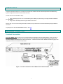
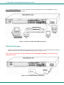
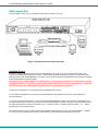
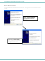
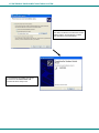
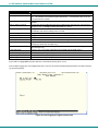
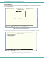
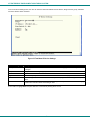
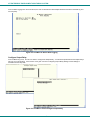
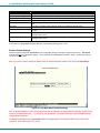
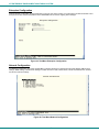
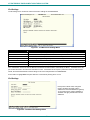
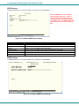
ENVIROMUX® Series Serial Control Manual E-16D/-5D/-2D Enterprise Environment Monitoring System Front and Rear View of E-16D Front View of E-5D Front View of E-2D MAN154-SCM Rev Date 4/10/18 TRADEMARK ENVIROMUX is a registered trademark of Network Technologies Inc in the U.S. and other countries. COPYRIGHT Copyright © 2005, 2018 by Network Technologies Inc. All rights reserved. No part of this publication may be reproduced, stored in a retrieval system, or transmitted, in any form or by any means, electronic, mechanical, photocopying, recording, or otherwise, without the prior written consent of Network Technologies Inc, 1275 Danner Drive, Aurora, Ohio 44202. CHANGES The material in this guide is for information only and is subject to change without notice. Network Technologies Inc reserves the right to make changes in the product design without reservation and without notification to its users. Firmware Version Current Firmware version 2.53 CAUTION RISK OF ELECTRIC SHOCK. Do not remove cover. No user serviceable components inside. All repairs and maintenance must be performed by authorized service personnel only. CAUTION Turn OFF power to the ENVIROMUX and discharge your body’s static electric charge by touching a grounded surface or use a grounding wrist strap before performing any connections to the unit. CAUTION For continued protection against fire and electric shock this device should only be connected to an AC mains outlet equipped with a proper ground terminal. i TABLE OF CONTENTS INTRODUCTION............................................................................................................................................................. 5 HARDWARE CONNECTION .......................................................................................................................................... 5 Terminal Connection.................................................................................................................................................... 5 Ethernet Connection .................................................................................................................................................... 6 USB Console Port........................................................................................................................................................ 7 Installing Drivers ....................................................................................................................................................... 7 Installing an Unsigned Driver in Windows 8 and 10 (x64) ...................................................................................... 12 SOFTWARE CONNECTION......................................................................................................................................... 13 Connect to ENVIROMUX from a Terminal Program ................................................................................................. 13 Connect to ENVIROMUX from Command Line......................................................................................................... 14 Connect Via Telnet ................................................................................................................................................. 14 Connect Via SSH .................................................................................................................................................... 14 USING THE TEXT MENU ............................................................................................................................................. 16 Monitoring ............................................................................................................................................................... 16 Configure Remote Digital Inputs and Output Relays.............................................................................................. 33 System Configuration ............................................................................................................................................. 34 Enterprise Configuration ......................................................................................................................................... 36 Network Configuration ............................................................................................................................................ 36 User Configuration .................................................................................................................................................. 42 Security Configuration ............................................................................................................................................ 46 Event and Data Logs .............................................................................................................................................. 50 System Information ................................................................................................................................................. 53 Reboot .................................................................................................................................................................... 53 Text Menu for Non-Administrative Users................................................................................................................... 54 Monitoring ............................................................................................................................................................... 54 User Accessible Settings ........................................................................................................................................ 56 TABLE OF FIGURES Figure 1- Connect a terminal for direct RS232 serial communication ................................................................................................ 5 Figure 2- Connect a terminal using USB Console port ...................................................................................................................... 6 Figure 3- Connect ENVIROMUX to the Ethernet ............................................................................................................................... 6 Figure 4- Connect terminal to USB Console port............................................................................................................................... 7 Figure 5- Text Menu Login screen ................................................................................................................................................... 13 Figure 6- Text Menu- Administrator Main Menu............................................................................................................................... 14 Figure 7- Text Menu- User Main Menu ............................................................................................................................................ 15 Figure 8- Text Menu-Monitoring Menu............................................................................................................................................. 16 Figure 9- Text Menu-Sensor Status ................................................................................................................................................. 17 Figure 10- Text Menu- Digital Input Status ...................................................................................................................................... 17 Figure 11- Text Menu-View IP Devices............................................................................................................................................ 18 Figure 12- Text Menu- View Output Relay Status............................................................................................................................ 18 Figure 13- Text Menu-View Remote Digital Inputs .......................................................................................................................... 19 Figure 14- Text Menu-View Remote Output Relays ........................................................................................................................ 19 Figure 15- Text Menu-View Power Supply Status ........................................................................................................................... 20 Figure 16- Text Menu-Configure Sensors list .................................................................................................................................. 21 ii Figure 17- Text Menu-Configuration Menu for Sensor..................................................................................................................... 21 Figure 18- Text Menu-Sensor Settings ............................................................................................................................................ 22 Figure 19- Text Menu-Non-Critical and Critical Alert Settings.......................................................................................................... 23 Figure 20- Text Menu-Sensor Data Logging.................................................................................................................................... 24 Figure 21- Configure Digital Input Sensors ...................................................................................................................................... 24 Figure 22- Digital Input Sensor Settings Menu ................................................................................................................................ 25 Figure 23- Digital Input Alert Settings .............................................................................................................................................. 25 Figure 24- Data Logging for Digital Input Sensors ...........................................................................................................................26 Figure 25- Text Menu-Configure IP Devices List ............................................................................................................................. 27 Figure 26- Text menu-Configuration Menu for IP Devices ............................................................................................................... 27 Figure 27-Text Menu-IP Device Settings ......................................................................................................................................... 28 Figure 28- Text Menu-IP Device Alert Settings................................................................................................................................ 29 Figure 29- Text Menu-IP Device Data Logging................................................................................................................................ 30 Figure 30- Text Menu- Select Configure Output Relay .................................................................................................................... 30 Figure 31- Text Menu- Output Relay Settings.................................................................................................................................. 31 Figure 32- Text Menu- Output Relay Alert Settings ......................................................................................................................... 31 Figure 33- Text Menu- IP Camera List for Configuration ................................................................................................................. 32 Figure 34- Text Menu- IP Camera Settings ..................................................................................................................................... 32 Figure 35- Text Menu-Configure Remote Digital Inputs and Output Relays .................................................................................... 33 Figure 36- Text Menu- System Configuration .................................................................................................................................. 34 Figure 37- Text Menu-Time Settings menu...................................................................................................................................... 34 Figure 38- Text Menu-Restore Default Settings............................................................................................................................... 35 Figure 39- Text Menu-Enterprise Configuration............................................................................................................................... 36 Figure 40- Text Menu-Network Configuration .................................................................................................................................. 36 Figure 41- Text Menu-IPv4 Settings Menu ...................................................................................................................................... 37 Figure 42- Text Menu-IPv6 Settings Menu ...................................................................................................................................... 37 Figure 43- Text Menu-SMTP Server Settings .................................................................................................................................. 38 Figure 44- Text Menu-SNMP Server Settings.................................................................................................................................. 38 Figure 45- Text Menu-Misc. Service Settings menu ........................................................................................................................ 39 Figure 46- Text Menu-3G Data Connect Settings ............................................................................................................................ 40 Figure 47- Text Menu-VLAN Settings .............................................................................................................................................. 41 Figure 48- Text Menu-User Configuration........................................................................................................................................ 42 Figure 49- Text Menu-Confirm to add new user .............................................................................................................................. 42 Figure 50- Text Menu-Configuration List for User............................................................................................................................ 43 Figure 51- Text Menu-User Account Settings .................................................................................................................................. 43 Figure 52- Text Menu-User Contact Settings................................................................................................................................... 44 Figure 53- Text Menu-User Activity Schedule.................................................................................................................................. 45 Figure 54-Text Menu- SNMP User Settings..................................................................................................................................... 45 Figure 55- Text Menu-Security Configuration .................................................................................................................................. 46 Figure 56- Text Menu-Authentication Settings................................................................................................................................. 47 Figure 57- Text Menu-IP Filtering .................................................................................................................................................... 48 Figure 58- Text Menu-Configure IP Filter rule.................................................................................................................................. 48 Figure 59- Text Menu-Event & Data Logs........................................................................................................................................ 50 Figure 60- Text Menu-View Event Log............................................................................................................................................. 50 Figure 61- Text Menu-View Data Log .............................................................................................................................................. 51 Figure 62- Text Menu-Event Log Settings ....................................................................................................................................... 52 Figure 63-Text Menu-Data Log Settings .......................................................................................................................................... 52 Figure 64-Text Menu-System Information........................................................................................................................................ 53 Figure 65- Text Menu-Reboot the ENVIROMUX ............................................................................................................................. 53 Figure 66- Text Menu-User Main Menu ........................................................................................................................................... 54 Figure 67-Text Menu-User Monitoring Menu ................................................................................................................................... 54 Figure 68- Text Menu-User accessible status menus ...................................................................................................................... 55 Figure 69- Text Menu-User Accessible Settings.............................................................................................................................. 56 iii Figure 70- Text Menu-User Account Settings .................................................................................................................................. 56 Figure 71- Text Menu-User Contact Settings................................................................................................................................... 57 Figure 72- Text Menu-User Activity Schedule.................................................................................................................................. 58 Figure 73- Text Menu-User SNMP Settings..................................................................................................................................... 58 iv INTRODUCTION This manual provides instruction for connection and control of the E-16D/ E-5D and E-2D Enterprise Environment Monitoring Systems using serial connection and the built-in text menu. The text menu can be accessed two ways: 1. using a terminal program on a PC connected through the “RS232” port (E-16D only) or through the USB “CONSOLE” port (all models). 2. using Telnet or the SSH protocol through an Ethernet connection Only the user “root” can connect using a terminal connection, but up to 8 users can connect simultaneously using the Ethernet connection. To quickly return to the main ENVIROMUX manual, click here. HARDWARE CONNECTION Terminal Connection To use the “RS232” port, connect one end of a CAT5 patch cable (supplied) to the port labeled “RS232” on the rear of the E16D (or the “RS232 AUX” on the E-5D). Plug the other end of the CAT5 cable into an RJ45-to-DB9F adapter (supplied), and connect the adapter to the RS232 port on the control terminal. Follow the instruction under “RS232 Connection” on page 13 for configuration and use of the Serial Control feature. Figure 1- Connect a terminal for direct RS232 serial communication v NTI ENTERPRISE ENVIRONMENT MONITORING SYSTEM To use the USB “CONSOLE” port, connect a USB cable (2 meter cable supplied) between the ENVIROMUX and your PC. Then install the drivers as described on page 7. Figure 2- Connect a terminal using USB Console port Ethernet Connection To make a connection over the Ethernet, from anywhere on the local area network, connect a CAT5/5e/6 Ethernet cable with RJ45 male connectors on the ends, wired straight through (pin 1 to pin 1, pin 2 to pin 2, etc.). Note: A direct connection from a computer’s Ethernet port to the ENVIROMUX “ETHERNET” port may also be made using the same cable. Figure 3- Connect ENVIROMUX to the Ethernet 6 NTI ENTERPRISE ENVIRONMENT MONITORING SYSTEM USB Console Port To use the USB “Console” port, you will need to install drivers provided on your CD. Figure 4- Connect terminal to USB Console port Installing Drivers You will only need to install drivers the first time the ENVIROMUX is connected to your PC with Windows XP, 2000, Vista, Windows 7 and Windows 8 (32 and 64 bit versions). (Drivers will automatically install when connected to a Windows 10 PC.) After the first time, when the ENVIROMUX is connected, your PC should recognize the ENVIROMUX and re-assign the COM port. Follow the steps below to install the drivers. Note: When trying to load the USB driver to a Windows 8 PC, you will likely be stopped by an “unsigned driver” warning, even though the driver you are trying to load is actually a Microsoft driver from an earlier operating system. Follow the instruction on page 12 to disable this warning and be able to proceed with driver installation. 1. Make sure the USB cable is connected between the ENVIROMUX and your PC. 2. Power ON the ENVIROMUX. The PC will see the ENVIROMUX as “New Hardware” and create a virtual COM port to communicate with it. 3. You will be prompted to load drivers. A driver file compatible with Windows XP, 2000, Vista, Windows 7 and Windows 8 (32 and 64 bit versions) can be found on the CD that came with your ENVIROMUX. Browse to the drive your Product Manual CD is in and locate and select the file named “enviromux.inf” in a directory named “windows-drivers\32bit or \64bit” depending upon your operating system. The .inf file will direct your PC to locate and install the file usbser.sys (already on your PC, comes with Windows). Installing the usbser.sys file should happen automatically. When finished, Windows will indicate installation is successful. 7 NTI ENTERPRISE ENVIRONMENT MONITORING SYSTEM Windows XP-32 bit Installation Your typical installation will include windows like the ones that follow. The images below are from a Windows XP SP2 32 bit installation. A. Windows will want to check the internet for drivers. Choose “No, not this time” because the drivers are unique to the ENVIROMUX. B. You can try to “Install the software automatically” but if windows doesn’t check the CD, you will need to use “Install from a list or specific location” instead. 8 NTI ENTERPRISE ENVIRONMENT MONITORING SYSTEM C. Let the New Hardware Wizard search for the driver, but direct it to the drive the Product Manual CD is in and the directory of either the 32 bit driver or the 64 bit driver. D. Once the driver is installed, you will get this screen and the ENVIROMUX USB Console Port will be ready to use. 9 NTI ENTERPRISE ENVIRONMENT MONITORING SYSTEM Windows 7-64 bit Installation A Windows 7 64 bit installation has a few extra steps. The images below are from a Windows 7, 64-bit installation. A. Upon ENVIROMUX power ON, the driver cannot be found. Press “Close”. B. Open the Device Manager and select the ENVIROMUX in the device list. Right-click and open “Properties”. Select “Update Driver Software”. C. From the next window, select “Browse my computer for driver software”. Tip: The Device Manager can be opened by right-clicking on “My Computer” on the desktop, selecting “Properties”, and selecting “Device Manager”. D. In the next window, enter the path to the .inf driver file (on the Product Manual CD). Press “Next”. 10 NTI ENTERPRISE ENVIRONMENT MONITORING SYSTEM E. You will probably get this warning that Windows can’t verify the publisher of the driver software. Select “Install this driver software anyway. “ F. The driver will load. This might take a minute while it searches your computer for the usbser.sys file it needs. Once it does, you will get a window telling you Windows is finished. Take note of the COM port number it assigned. (This one assigned COM3.) 11 NTI ENTERPRISE ENVIRONMENT MONITORING SYSTEM Installing an Unsigned Driver in Windows 8 and 10 (x64) When trying to load the USB driver into a Windows 8 or 10 PC in order to use the USB Console port on an NTI product, you may encounter a window that prevents it because it is an “unsigned driver”, in spite of the fact it is actually a Microsoft driver from an earlier operating system. The steps to enable the installation of the USB driver on Windows 8 are as follows: 1. From Windows 8 Control Panel choose General –> Under “Advanced Startup” –> Restart now. Now the system will restart and might take some minutes to show up the boot menu. Wait for It patiently. After some time you will be prompted with a menu with the following options. 1. Continue 2. Troubleshoot 3. Turn off 2. Choose “Troubleshoot” Then the following menu appears: Refresh your PC Reset your PC Advanced Options 3. Choose “Advanced Options” Then the following menu appears: System Restore System Image Recovery Automatic Repair Command Prompt Windows Startup settings 4. Choose “Windows Startup Settings”, then Click Restart. Now the computer will restart and the boot menu appears. 5. Choose “Disable Driver Signature Enforcement” from the boot menu. Now Windows will start and you can follow the instructions on page 7 for the installation of the USB driver. The steps to enable the installation of the USB driver on Windows 10 are as follows: 1. 2. 3. 4. 5. 6. 7. 8. 9. Click the Start menu and select Settings. Click Update and Security. Click Recovery. Click Restart now under Advanced Startup. Click Troubleshoot. Click Advanced options. Click Startup Settings. Click Restart. On the Startup Settings screen press 7 or F7 to disable driver signature enforcement. Your computer will restart and you will be able to install non-digitally signed drivers. Note: If you restart your computer again the driver signature enforcement will be re-enabled. 12 NTI ENTERPRISE ENVIRONMENT MONITORING SYSTEM SOFTWARE CONNECTION The ENVIROMUX can be controlled serially through a text menu using a terminal program (e.g. HyperTerminal) when connected to the RJ45 “RS232” port or USB “Console” Port, or by using the Telnet or the SSH protocol when connected through the Ethernet Port (page 6). Either of these methods will work to access the ENVIROMUX text menu. The text menu can be used to control most functions of the ENVIROMUX as an alternative to the Web Interface (described in the main user manual). Connect to ENVIROMUX from a Terminal Program Note: Drivers must first be installed on the PC (page 7) if the terminal program is connected through a USB CONSOLE port. 1. Make sure the ENVIROMUX is powered ON and booted-up fully. Note: When using the “RS232 AUX” port on an E-5D for terminal connection, you must first configure the port to be used for “Console” connection through the web interface (ADMINISTRATION menu -> System Configuration -> Auxiliary Serial Port Configuration (page 59 of the ENVIROMUX Installation and Operation Manual)). Set the baud rate for a speed compatible with the connected terminal. After making this change, click “Save” and reboot the ENVIROMUX fully for the settings to take effect. 2. Using the terminal connected to the ENVIROMUX, start the terminal program (e.g. Windows HyperTerminal) and configure it as follows: direct connection (using the appropriate CPU local serial Com port) The COM port assigned to the USBto-serial connection can be found in 115200 bps the device manager or your PC 8 bits operating system. no parity 1 stop bit no flow control VT100 terminal mode. Note: To display special characters (German, Japanese, etc.) correctly in the Text Menu, use a terminal program that supports UTF8 character encoding (such as putty or TeraTerm). Also, the script may need to be set specific to your location. 3. Press <Enter> and a login prompt will appear- type <root> (all lowercase letters) and press <Enter>. 4. At “Password” type <nti> (all lowercase letters) and press <Enter>. Figure 5- Text Menu Login screen Note: User names and passwords are case sensitive. It is important to know what characters must be capitalized and what characters must not. Note: Only the user “root” can access the text menu when connected through the “USB CONSOLE” or “RS232” port. 13 NTI ENTERPRISE ENVIRONMENT MONITORING SYSTEM Connect to ENVIROMUX from Command Line To access the Text Menu from the command line, the ENVIROMUX must first be connected to the Ethernet. Connect Via Telnet Note: Telnet must be enabled through the web interface for a connection via Telnet to be possible (refer to the main user manual). SSH (below) is enabled by default. To open a telnet session to the ENVIROMUX, Issue the following command from the command line: telnet <ENVIROMUX hostname or IP address> <ENVIROMUX hostname> is the hostname configured in the workstation where the telnet client will run (through /etc/hosts or DNS table). It can also be just the IP address of the ENVIROMUX (default is 192.168.1.21). The user will be prompted for username and password to connect to the ENVIROMUX. Connect Via SSH To open an SSH session to a serial port, issue the following command from the command line: ssh -l <Username> <ENVIROMUX hostname or IP address> <Username> is any user configured to access the ENVIROMUX. The default user is “root”. <ENVIROMUX hostname> is the hostname configured in the workstation where the SSH client will run (through /etc/hosts or DNS table). It can also be just the IP address of the ENVIROMUX (default is 192.168.1.21). The user will be prompted for a password to connect to the ENVIROMUX. The default password is “nti” (all lowercase letters). The main menu of the Text Menu will be displayed whether you are connecting via USB Console,Telnet, or SSH. Figure 6- Text Menu- Administrator Main Menu 14 NTI ENTERPRISE ENVIRONMENT MONITORING SYSTEM If you are a user with only user privileges (no administrative privileges), the text menu will have more limited options. Figure 7- Text Menu- User Main Menu For more on the Text Menu options for non-administrative users, see page 54. 15 NTI ENTERPRISE ENVIRONMENT MONITORING SYSTEM USING THE TEXT MENU Text Menu Navigation To move up and down the numbered menu items or toggle through field options, use the arrow keys. To jump from menu item to another quickly, press the numbered key above the QWERTY keys (the numberpad number keys are not used). To move from menu list to action key (such as “Logout” in Figure 7), press <Tab>. To exit an action or menu, press <Esc>. To select a highlighted item or move to another field in a configuration page, press <Enter>. Be sure to Tab to “Save” and press <Enter> when configuration changes are made. To return from “Save” back to a field on the configuration page, press <Tab>. The Administrators Main Menu is broken into 9 categories: Function Description Monitoring Monitor and configure the sensors, accessories and IP devices System Configuration Set the ENVIROMUX time settings or reset the unit to factory default settings Enterprise Configuration Configure system settings Network Configuration Configure network settings User Configuration Configure user access settings Security Configuration Configure security settings Event and Data Logs View and configure the Event and Data Logs System Information View system and network settings Reboot Enables the user to reboot the ENVIROMUX Monitoring The Monitoring menu lists choices for viewing the status of items monitored by the ENVIROMUX as well as for configuring how they are monitored and how or if alert messages will be sent. Note: Selections 1-11 are shown initially. Page down or scroll down to display selections 12-16. Figure 8- Text Menu-Monitoring Menu 16 NTI ENTERPRISE ENVIRONMENT MONITORING SYSTEM View Sensors The View Sensors selection will show the present status of each analog sensor connected to the ENVIROMUX. The current value being reported by the sensor and the state (whether Normal or Alert) will be shown. If the sensor is in alert status, pressing the <Enter> key would provide the option to either acknowledge the alert or dismiss it. Figure 9- Text Menu-Sensor Status View Digital Inputs The View Digital Inputs selection will show the present status of each dry contact sensor connected to the ENVIROMUX. The current value being reported by the sensor and the state (whether Normal or Alert) will be shown. If the sensor is in alert status, pressing the <Enter> key would provide the option to either acknowledge the alert or dismiss it. Figure 10- Text Menu- Digital Input Status 17 NTI ENTERPRISE ENVIRONMENT MONITORING SYSTEM View IP Devices The View IP Devices selection will show the present status of each IP Device monitored by the ENVIROMUX. The current value being reported by the IP Device and the state (whether Normal or Alert) will be shown. If the IP Device is in alert status, pressing the <Enter> key would provide the option to either acknowledge the alert or dismiss it. Figure 11- Text Menu-View IP Devices View Output Relay The View Output Relay selection will show the present state of the Output Relay on the ENVIROMUX. To manually change its state, press <Enter> and select between Inactive and Active. Press <Enter> to open window to change state if desired. Figure 12- Text Menu- View Output Relay Status 18 NTI ENTERPRISE ENVIRONMENT MONITORING SYSTEM View Remote Digital Inputs The View Remote Digital Inputs selection will show the present status of each dry contact sensor connected to expansion devices (i.e. E-DI16DO16) connected to the ENVIROMUX. The current value being reported by the sensor and the state (whether Normal or Alert) will be shown. If the sensor is in alert status, pressing the <Enter> key would provide the option to either acknowledge the alert or dismiss it. Figure 13- Text Menu-View Remote Digital Inputs View Remote Output Relay The View Remote Output Relay selection will show the present state of the Remote Output Relays connected to the ENVIROMUX through expansion devices (i.e. E-DI16DO(R)16). To manually change its state, press <Enter> and select between Inactive and Active. Figure 14- Text Menu-View Remote Output Relays 19 NTI ENTERPRISE ENVIRONMENT MONITORING SYSTEM View Power Supply Status The View Power Supply Status selection will show the present state of the power supply in the ENVIROMUX. If the power is OFF, status will change to alert. Figure 15- Text Menu-View Power Supply Status 20 NTI ENTERPRISE ENVIRONMENT MONITORING SYSTEM Configure Sensors The Configure Sensors menu lists the temperature and humidity sensors connected to the ENVIROMUX. Press <Enter> to open the configuration menu for the selected sensor. Figure 16- Text Menu-Configure Sensors list The configuration menu for the sensor includes options to enter the Sensor Settings, Non-Critical Alert Settings, Critical Alert Settings, and Data Logging. Figure 17- Text Menu-Configuration Menu for Sensor 21 NTI ENTERPRISE ENVIRONMENT MONITORING SYSTEM From the Sensor Settings menu enter the Description for the sensor and select which sensor group the sensor should belong to (1 or 2). Figure 18- Text Menu-Sensor Settings Sensor Settings Description Description The description of the sensor that will be viewed in the Summary page and in the body of alert messages Groups Assign the sensor to one or more groups (1 -8) (see also page 44) Units This lets the operator choose between Celsius and Fahrenheit as the temperature measurement unit. Min. Level Displays the minimum value that this sensor will report Max. Level Displays the maximum value that this sensor will report Minimum Non-Critical -Threshold The user must define the lowest acceptable value for the sensors. If the sensor measures a value below this threshold, the sensor will move to non-critical alert status. The assigned value should be within the range defined by Minimum Level and Maximum Level and lower than the assigned Maximum Threshold value. If values out of the range are entered, and error message will be shown. Maximum NonCritical Threshold The user must define the highest acceptable value for the sensors. If the sensor measures a value above this threshold, the sensor will move to non-critical alert status. The assigned value should be within the range defined by Minimum Level and Maximum Level and higher than the assigned Minimum Threshold value. If values out of the range are entered, and error message will be shown. Minimum Critical Threshold The user must define the lowest acceptable value for the sensors. If the sensor measures a value below this threshold, the sensor will move to alert status. The assigned value should be within the range defined by Minimum Level and Maximum Level, lower than the assigned Maximum Threshold value, and lower than the Minimum Non-Critical Threshold value. If values out of the range are entered, and error message will be shown. Maximum Critical Threshold The user must define the highest acceptable value for the sensors. If the sensor measures a value above this threshold, the sensor will move to alert status. The assigned value should be within the range defined by Minimum Level and Maximum Level, higher than the assigned Minimum Threshold value, and higher than the Maximum Non-Critical Threshold value. If values out of the range are entered, and error message will be shown. Refresh Rate Determines how often the displayed sensor value is refreshed on the Sensor page. A numeric value and a measurement unit (minimum 1 seconds, maximum 999 minutes) should be entered. Press <Tab> to highlight Save and press <Enter> to save before pressing <Esc> to exit. 22 NTI ENTERPRISE ENVIRONMENT MONITORING SYSTEM From the Non-Critical or Critical Alert Settings menu, the user can enable/disable alert messages to be sent when the sensor is in an alert state and configure when and how alert messages are sent. Additionally, from the Critical Alert Settings menu, the user can configure the ENVIROMUX to capture a snapshot from an IP camera and attach the image to the alert message sent via email. Figure 19- Text Menu-Non-Critical and Critical Alert Settings Alert Settings Disable alerts Change to “Yes” to prevent alerts from being sent when this sensor’s status changes Alert Delay The alert delay is an amount of time the sensor must be in an alert condition before an alert is sent. This provides some protection against false alarms. The Alert Delay value can be set for 0-999 seconds or minutes. Notify Again Time Enter the amount of time in seconds, minutes, or hours (1-999) before an alert message will be repeated Notify on Return to Normal The user can also be notified when the sensor readings have returned to the normal range by changing to “Yes” for "Notify on return to normal" for a sensor. Auto Acknowledge Change to “Yes” to have alert notifications in the summary page return to normal state automatically when sensor readings return to normal. Enable Email Alerts Change to “Yes” to have alert notifications sent via Email Enable Syslog Alerts Change to “Yes” to have alert notifications sent via Syslog messages Enable SNMP traps Change to “Yes” to have alert notifications sent via SNMP traps (v2c) Enable SMS Alerts Change to “Yes” to have alert notifications sent via SMS (requires GSM modem) Email Subject Enter the subject to be viewed when an email alert message is received Attach IP camera capture Change to “Yes” to enable a snapshot to be taken from an IP camera and attached to the alert message (for critical alert messages only.) Selected IP camera Select which IP camera to take a snapshot from to be attached to an alert message (for critical alert messages only) Associated output relay Choose which output relay to change state when sensor is in alert Output relay on alert Choose the state the output relay should be in when the sensor is in alert Output relay on return Choose the state the output relay should be in when the sensor returns to normal Press <Tab> to highlight Save and press <Enter> to save before pressing <Esc> to exit. 23 NTI ENTERPRISE ENVIRONMENT MONITORING SYSTEM From the Data Logging menu for the sensor, the user can decide if the data sampled should be recorded in the Data Log and how frequently. Figure 20- Text Menu-Sensor Data Logging Configure Digital Inputs The Configure Digital Input Sensors menu lists the contact sensors connected to the ENVIROMUX. Press <Enter> to open the configuration menu for the selected contact sensor. (The Water Sensor menu contains the same options as the contact sensor menu.) The configuration menu for the Digital Inputs includes options to enter the Digital Input Settings, Alert Settings, and Data Logging. Figure 21- Configure Digital Input Sensors 24 NTI ENTERPRISE ENVIRONMENT MONITORING SYSTEM Water sensors and contact sensors are each configured much like the temperature and humidity sensors previously described. Only the Sensor Settings menu (below) is different. Alert settings and data logging menus are as seen in Figure 19 and Figure 20. Instead of threshold and minimum/maximum levels settings, water sensors and contact sensors are either open contact or closed contact sensors. Therefore, the field “Normal Status” is provided to select the status of the sensor when it is not in an alert state. Select between Open contacts, or Close contacts for the normal status of the sensor. (Water sensors are open contact when not in an alert state.) Figure 22- Digital Input Sensor Settings Menu From the Alert Settings menu, the user can enable/disable alert messages to be sent when the sensor is in an alert state and configure when and how alert messages are sent. Figure 23- Digital Input Alert Settings 25 NTI ENTERPRISE ENVIRONMENT MONITORING SYSTEM Alert Settings Disable alerts Change to “Yes” to prevent alerts from being sent when this sensor’s status changes Alert Delay The alert delay is an amount of time the sensor must be in an alert condition before an alert is sent. This provides some protection against false alarms. The Alert Delay value can be set for 0-999 seconds or minutes. Notify Again Time Enter the amount of time in seconds, minutes, or hours (1-999) before an alert message will be repeated Notify on Return to Normal The user can also be notified when the sensor readings have returned to the normal range by changing to “Yes” for "Notify on return to normal" for a sensor. Auto Acknowledge Change to “Yes” to have alert notifications in the summary page return to normal state automatically when sensor readings return to normal. Enable Syslog Alerts Change to “Yes” to have alert notifications sent via Syslog messages Enable SNMP traps Change to “Yes” to have alert notifications sent via SNMP traps (v2c) Enable Email Alerts Change to “Yes” to have alert notifications sent via Email Email Subject Enter the subject to be viewed when an email alert message is received Attach IP camera capture Change to “Yes” to enable a snapshot to be taken from an IP camera and attached to the alert message (for critical alert messages only.) Selected IP camera Select which IP camera to take a snapshot from to be attached to an alert message (for critical alert messages only) Enable SMS Alerts Change to “Yes” to have alert notifications sent via SMS (requires GSM modem) Associated output relay Choose which output relay to change state when sensor is in alert Output relay on alert Choose the state the output relay should be in when the sensor is in alert Output relay on return Choose the state the output relay should be in when the sensor returns to normal Press <Tab> to highlight Save and press <Enter> to save before pressing <Esc> to exit. From the Data Logging menu for the Digital Input sensor, the user can decide if the data sampled should be recorded in the Data Log and how frequently. Figure 24- Data Logging for Digital Input Sensors 26 NTI ENTERPRISE ENVIRONMENT MONITORING SYSTEM Configure IP Devices The Configure IP Devices menu lists the IP Devices monitored by the ENVIROMUX. Press <Enter> to open the configuration menu for the selected IP Device. Figure 25- Text Menu-Configure IP Devices List The configuration menu for the IP Device includes options to enter the IP Device Settings, Alert Settings, and Data Logging. Figure 26- Text menu-Configuration Menu for IP Devices 27 NTI ENTERPRISE ENVIRONMENT MONITORING SYSTEM From the IP Device Settings menu, the user can enter the name and address of the IP Device, assign a sensor group, and define how the IP Device will be monitored. Figure 27-Text Menu-IP Device Settings IP Device Settings Description Description The description of the IP Device that will be viewed in the Summary page and in the body of alert messages Group Assign the IP device to a group (1 -8) IP Address The IP address of the IP Device Ping Period Enter the frequency in minutes or seconds that the ENVIROMUX should ping the IP Device Timeout Enter the length of time in seconds to wait for a response to a ping before considering the attempt a failure Retries Enter the number of times the ENVIROMUX should ping a non-responsive IP device before changing its status from normal to alarm and sending an alert Press <Tab> to highlight Save and press <Enter> to save before pressing <Esc> to exit. 28 NTI ENTERPRISE ENVIRONMENT MONITORING SYSTEM From the Alert Settings menu, the user can enable/disable alert messages to be sent when the IP Device is not responding and configure when and how alert messages are sent. Figure 28- Text Menu-IP Device Alert Settings Alert Settings Description Disable alerts Change to “Yes” to prevent alerts from being sent when this IP Device’s status changes Notify Again Time Enter the amount of time in seconds, minutes, or hours (1-999) before an alert message will be repeated Notify on Return to Normal The user can also be notified when the IP Device’s state has returned to the normal by changing to “Yes” for "Notify on return to normal" for a sensor. Auto Acknowledge Change to “Yes” to have alert notifications in the summary page return to normal state automatically when sensor readings return to normal. Enable Email Alerts Change to “Yes” to have alert notifications sent via Email Enable Syslog Alerts Change to “Yes” to have alert notifications sent via Syslog messages Enable SNMP traps Change to “Yes” to have alert notifications sent via SNMP traps (v2c) Email Subject Enter the subject to be viewed when an email alert message is received Enable SMS Alerts Change to “Yes” to have alert notifications sent via SMS (requires GSM modem) Siren Change to “Yes” to activate the siren circuit during an alert condition Beacon Change to “Yes” to activate the beacon circuit during an alert condition Press <Tab> to highlight Save and press <Enter> to save before pressing <Esc> to exit. 29 NTI ENTERPRISE ENVIRONMENT MONITORING SYSTEM From the Data Logging menu for the IP Device, the user can decide if the data sampled should be recorded in the Data Log and how frequently. Figure 29- Text Menu-IP Device Data Logging Configure Output Relay From the Monitoring menu, the user can select to configure the Output Relay. You will first be presented with the Output Relays list (only one in this product). Press <Enter> to be given a choice of configuring Output Relay Settings or Alert Settings to associate with the relay state. Figure 30- Text Menu- Select Configure Output Relay 30 NTI ENTERPRISE ENVIRONMENT MONITORING SYSTEM Select the Output Relay Settings to access a menu where the description of the Output Relay can be defined. This definition will be presented in the View Output Relays list as well as in the description field when viewing the list through the WEB interface. The group this relay will be associated with can be defined here to determine who will receive alerts generated by the relay state change, if any. The “Normal Status” of the relay is defined here which determines what the ENVIROMUX will consider a normal versus alert condition for the relay. Figure 31- Text Menu- Output Relay Settings Select the Alert Settings to access a menu for enabling alert messages that can be sent when the relay changes from its “Normal” state. Figure 32- Text Menu- Output Relay Alert Settings 31 NTI ENTERPRISE ENVIRONMENT MONITORING SYSTEM Configure IP Cameras From the Monitoring menu, the user can select to configure IP Cameras. You will first be presented with the IP Cameras list (up to 8 can be configured). Select an IP Camera in the list and press <Enter> to open the IP Camera Settings menu. Figure 33- Text Menu- IP Camera List for Configuration Figure 34- Text Menu- IP Camera Settings Camera Settings Description View Change to “Yes” to enable images from the IP Camera to appear in the view when selecting the IP Cameras from the Monitoring menu in the WEB interface Name Characters entered will appear in any listing of the IP camera selection. Image URL Enter the full path to the image file captured by the IP camera under “Image URL”. IP Address the IP address for the IP camera. Refresh Time Enter a refresh time period in increments of 100 msec (milliseconds). That is, a value of 1 = 100 msec, 5 = 500 msec , 10 = 1000 msec (or 1 second). The images can be set to be refreshed every 100 msec (.1 second) up to 99,900 msec (almost 100 seconds). 32 NTI ENTERPRISE ENVIRONMENT MONITORING SYSTEM Configure Remote Digital Inputs and Output Relays Remote Digital Inputs and Output relays can be configured just the same as those directly attached to the ENVIROMUX (pages 24 and 30). Figure 35- Text Menu-Configure Remote Digital Inputs and Output Relays 33 NTI ENTERPRISE ENVIRONMENT MONITORING SYSTEM System Configuration Under System Configuration (from the Main Menu), select “Time Settings” to enter the time of day, time zone, enable daylight saving time, or NTP server settings. Also, select “Configuration Backup & Restore” to clear all configuration and user settings and restore the ENVIROMUX to settings as received from the factory. Figure 36- Text Menu- System Configuration Time Settings On the Time Settings menu, the user can designate what time zone the unit is associated with, set the date and time manually or configure the ENVIROMUX to get this information from an NTP server. Figure 37- Text Menu-Time Settings menu 34 NTI ENTERPRISE ENVIRONMENT MONITORING SYSTEM Time Settings Description Time Zone Enter the appropriate time zone Enable Daylight Saving Change to “Yes” to have the time change in accordance Daylight Saving Time rules Set Date Enter the system date in MM-DD-YYYY format Set Time Enter the system time of day in hh:mm:ss format Enable NTP Change to “Enabled” to allow the ENVIROMUX to automatically sync up with a time server via NTP NTP server If the NTP is enabled, enter the Domain Name or IP address of the NTP server NTP Frequency Enter the frequency (in minutes) for the ENVIROMUX to query the NTP server (minimum is 5 minutes) E-mail Time Stamp Change to “Enabled” to allow the ENVIROMUX to automatically apply a time stamp to e-mail messages sent to users SMS Time Stamp Change to “Enabled” to allow the ENVIROMUX to automatically apply a time stamp to SMS messages sent to users Press <Tab> to highlight Save and press <Enter> to save before pressing <Esc> to exit. Restore Default Settings Select this option to restore the ENVIROMUX to the configuration settings it had upon receipt from the factory. Be careful! This will erase all user configuration settings. Upon restoration, the ENVIROMUX will reboot. Allow 1 minute before trying to reconnect and log in again. Note: You can also restore settings to defaults from the “Restore Defaults” button on the front of the ENVIROMUX. Figure 38- Text Menu-Restore Default Settings Note: If “Restore Defaults” is used, the IP address will also be restored to its default address (192.168.1.21) with a login name “root” and password “nti”. To restore the root password to “nti” without having to restore all default settings, contact NTI for assistance. To identify the IP address of the ENVIROMUX without restoring defaults, use the Device Discovery Tool (see main manual for “Device Discovery Tool”- pg 21). 35 NTI ENTERPRISE ENVIRONMENT MONITORING SYSTEM Enterprise Configuration Under Enterprise Configuration (from the Main Menu), enter the unit name, location, the contact person emails should refer to and their phone number, and the email address of the ENVIROMUX to be used for outgoing alert messages. Figure 39- Text Menu-Enterprise Configuration Network Configuration The Network Configuration menu (from the Main Menu) includes submenus for applying IPv4 and IPv6 Settings, SMTP server settings, SNMP settings, miscellaneous settings to enable services for SSH, Telnet, HTTP, HTTPS and Web Timeout, 3G data and VLAN connection settings. Figure 40- Text Menu-Network Configuration 36 NTI ENTERPRISE ENVIRONMENT MONITORING SYSTEM IPv4 Settings The IP Settings menu contains the network connection settings for the ENVIROMUX. Figure 41- Text Menu-IPv4 Settings Menu IP Settings Description IPv4 Mode Select between Static (manual) , or DHCP (automatic IP and DNS) settings IPv4 Address Enter a valid IPv4 address (default value is 192.168.1.21) IPv4 Subnet Mask Enter a valid subnet mask (default value is 255.255.255.0) Default Gateway Enter a valid gateway (default gateway value is 192.168.1.1) Preferred DNS Enter a preferred domain name server address Alternate DNS Enter an alternate domain name server address DNS Timeout Enter a value from 1-30 (seconds) to query a DNS server before timing out If the administrator chooses to have the DNS and IP address information filled in automatically via DHCP, the SMTP server and port number still need to be entered for email alerts to work. If the SMTP server requires a password in order for users to send emails, the network administrator must first assign a user name and password to the ENVIROMUX. Press <Tab> to highlight Save and press <Enter> to save before pressing <Esc> to exit. IPv6 Settings If IPv6 protocol will be used, change the mode to “Enabled” and apply valid in addresses for the IPv6 address and gateway. To use a 6to4 tunnel, change “Disabled” to “Enabled” and apply valid local and remote addresses. Figure 42- Text Menu-IPv6 Settings Menu 37 NTI ENTERPRISE ENVIRONMENT MONITORING SYSTEM SMTP Settings The SMTP Settings menu contains the SMTP server settings for the ENVIROMUX. Note: The SMTP server port number is shown in Figure 43 as "25". This is a common port number assigned, but not necessarily the port number assigned to your SMTP server. For SMTP servers that support SSL, the common port number is 465. Figure 43- Text Menu-SMTP Server Settings SMTP Settings Description SMTP Server Enter a valid SMTP server name (e.g. yourcompany.com) Port Enter a valid port number (default port is 25) Use SSL Change to “Yes” if the SMTP server supports SSL Use Authentication Change to “Yes” if the SMTP server requires authentication to send email Username Enter a valid username to be used by the ENVIROMUX to send emails Password Enter a valid password assigned to the ENVIROMUX username SNMP Settings The SNMP Settings menu contains the SNMP server settings for the ENVIROMUX. Figure 44- Text Menu-SNMP Server Settings 38 NTI ENTERPRISE ENVIRONMENT MONITORING SYSTEM SNMP Settings Enable SNMP agent Choose between v1/v2c, v3 , and v1/v2c/v3 SNMP agent version settings Enable SNMP traps Change to “Enabled” to enable SNMP traps to be sent Read-write community name Enter applicable name (commonly used- “private”) (not used as of this printing) Read-only community name Enter applicable name (commonly used- “public”) Read-Only Community Name The SNMP Read-only community name enables a user to retrieve "read-only" information from the ENVIROMUX using the SNMP browser and MIB file. This name must be present in the ENVIROMUX and in the proper field in the SNMP browser. Read-Write Community Name (This field is not used by the ENVIROMUX as of this printing) The SNMP Read-Write community name enables a user to read information from the ENVIROMUX and to modify settings on the ENVIROMUX using the SNMP browser and MIB file. This name must be present in the ENVIROMUX and in the proper field in the SNMP browser. Miscellaneous Service Settings The Misc. Service Settings menu contains selections to configure services running on the ENVIROMUX. Figure 45- Text Menu-Misc. Service Settings menu Service Settings Enable SSH Enable this to allow access to the ENVIROMUX via SSH Enable Telnet Enable this to allow access to the ENVIROMUX via Telnet The default setting is Disabled. Enable HTTP access Enable this to allow access to the ENVIROMUX via standard (non-secure) HTTP requests HTTP Port Port to be used for standard HTTP requests HTTPS Port Port to be used for HTTPS requests Web Timeout Number of minutes after which idle web uses will be logged-out (enter 0 to disable this feature) The administrator may assign a different HTTP Server Port than is used by most servers (80). 39 NTI ENTERPRISE ENVIRONMENT MONITORING SYSTEM 3G Data Connect Settings The 3G Data Connect Settings are used to enable the 3G data features of your SIM card if you have installed a USB modem with SIM card that has these features. Figure 46- Text Menu-3G Data Connect Settings 3G Data Connection Enable 3G Data Enable if you want the option to have the ENVIROMUX send alert messages through the USB modem and the option to access the web interface using the IP address assigned to the SIM card account. The default is disabled. NOTE: In order to access the web interface through the modem, the SIM card must have a “public” IP address Enable 3G as primary route Enable if you want all messages that are sent by the ENVIROMUX to go through the modem connection instead of the Ethernet. The default is disabled. Note: If this feature is enabled, and then later disabled, the ENVIROMUX must be rebooted to reset outgoing messaging parameters. APN Enter the APN address of the service provider (provided by the service provider) Dial String Enter the dial string required for data connection(provided by the service provider) Username Enter the username supplied by service provider for access to connection. Leave blank if no username is required. Password Enter the password supplied by service provider for access to connection. Leave blank if no password is required. To access the web interface through your USB modem, your SIM card must be configured to support 3G data connections and have a “public” IP address. The ENVIROMUX can be configured (above) to send all alert messaging through the USB modem instead of requiring an Ethernet connection for these messages. With a public IP address, you will also be able to access the web interface using the IP address of the SIM card for full control of the ENVIROMUX through the modem. With only a “private” IP address, you will still be able to have the ENVIROMUX send email messages, but no web interface access will be possible. Make sure the account associated with the SIM card also has SMS messaging enabled if this feature will be used. Contact your service provider to obtain a SIM card with the features you desire. 40 NTI ENTERPRISE ENVIRONMENT MONITORING SYSTEM VLAN Settings You can enable or disable 802.1Q VLAN support, and if it is enabled you can enter an VLAN ID. Enter a number between 0-4095 for your VLAN ID. Figure 47- Text Menu-VLAN Settings 41 NTI ENTERPRISE ENVIRONMENT MONITORING SYSTEM User Configuration The User Configuration menu lists all configured user names of the ENVIROMUX. A maximum of 15 users (other than root) can be configured. From this screen the administrative user can add users, go to the user configuration page to edit a user’s access to the ENVIROMUX, or delete a user from the list. Figure 48- Text Menu-User Configuration To add a user, Tab to “Add User” and press <Enter>. To edit a user’s configuration, select the listed username and press <Enter> To delete a user and their configuration, select a listed username, Tab to “Delete User”, and press <Enter>. You will be prompted for confirmation before deleting the user and configuration. When adding a new user, you will be prompted to confirm the addition of the user. At that point, the Configure User menu will open a user settings list with the username “userx” assigned, where x = the next consecutive number (up to 15) based on the quantity of users in the list (other than the root user). Figure 49- Text Menu-Confirm to add new user 42 NTI ENTERPRISE ENVIRONMENT MONITORING SYSTEM Figure 50- Text Menu-Configuration List for User User Account Settings Select “Account Settings” from the list and press <Enter>. A menu with the account settings for that specific user will open where you can either leave the name as “userx”, or change it. With the name assigned, fill in the remaining information as needed. Figure 51- Text Menu-User Account Settings Account Settings Description Username Enter the desired username for this user Password Enter a password that a user must use to login to the system A password must be assigned for the user’s login to be valid Passwords must be at least 1 keyboard character. Confirm Re-enter a password that a user must use to login to the system 43 NTI ENTERPRISE ENVIRONMENT MONITORING SYSTEM Account Settings Description Enabled Change to “Yes” to enable this user to access the ENVIROMUX Admin Change to “Yes” if this user should have administrative privileges Title Enter information as applicable (optional) Company Enter information as applicable (optional) Department Enter information as applicable (optional) LDAP CN “Common Name” assigned in the LDAP server account in an Active Directory. Often a name assigned that is different than the Username. If this is the same as the Username (above), this can be left blank. LDAP OU Enter the Organizational Unit the user belongs to in an Active Directory Format is <ou,ou,etc> More about User Privileges The root user (or any user with administrator rights) can change the root password and configure how the root user will receive alert messages. Users with administrative rights can change all configuration settings except for the root user name. User Contact Settings Select “Contact Settings” from the list and press <Enter>. A menu with the contact settings for that specific user will open. Figure 52- Text Menu-User Contact Settings Contact Settings Group 1-8 Change to “Yes” if the user should receive messages from sensors, IP devices and accessories in Groups 1-8 Email Alerts Change to “Yes” if the user should receive messages via email Brief Email Change to “Yes” if the user should receive messages with limited content via email Email address Enter a valid email address if the user should receive email alert messages Syslog alerts Change to “Yes” if the user should receive alerts via syslog messages Syslog Facility Select a Syslog Facility for the messages to be sent to- Local0 thru Local7 (default is Local0). SNMP traps Change to “Yes” if the user should receive alerts via SNMP traps Syslog/SNMP IP address Enter a valid syslog/SNMP IP address for the user to receive syslog/SNMP messages SMS Alerts Change to “Yes” if the user should receive alerts via SMS messages SMS Number Enter a valid phone number for the user to receive SMS messages Press <Tab> to highlight Save and press <Enter> to save before pressing <Esc> to exit. 44 NTI ENTERPRISE ENVIRONMENT MONITORING SYSTEM User Activity Schedule Select “Schedule” from the list and press <Enter>. A menu with the user activity settings for that specific user will open. Figure 53- Text Menu-User Activity Schedule Schedule Settings Schedule Type Always active- user will receive messages at all hours of each day Active during defined times- user will only receive alert messages during times as outlined below Day of Week-From: First day of the week the user should begin receiving messages Day of Week-To: Last day of the week the user should receive messages Hour From: First hour of the day the user should begin receiving messages Hour To: Last hour of the day the user should receive messages User SNMP Settings Figure 54-Text Menu- SNMP User Settings 45 NTI ENTERPRISE ENVIRONMENT MONITORING SYSTEM Security settings can be configured within each user configuration if the SNMP protocol has been selected for use (page 39). Settings Authentication Protocol Choose between MD5 or SHA to require authentication, or none to disable it. This only needs to be changed from “none” if SNMPv3 is used. Privacy Protocol Choose between DES or AES to encrypt SNMP readings or traps or none to disable encryption. If encryption is enabled, then the Authentication Protocol must also be set at “MD5” or “SHA”. Authentication Passphrase Assign the passphrase to be used to enable the receipt of SNMP messages. This only needs to be changed from “none” if SNMPv3 is used. Privacy Passphrase Assign the passphrase to be used to open and read readings or alert messages received via SNMPv3 Traps Type Choose which format traps should be received in, SNMP v1, v2c, or v3 After changing any settings in the user profile, press “Apply”. Security Configuration The Security Configuration menu provides two submenus for setting local versus LDAP authentication methods and for applying IP filtering rules to prevent unwanted access to the ENVIROMUX. Figure 55- Text Menu-Security Configuration 46 NTI ENTERPRISE ENVIRONMENT MONITORING SYSTEM Authentication Settings Security in the ENVIROMUX can be managed one of two ways; through the local settings (passwords assigned in user settings on page 43) or through an LDAP server. If security is configured to use LDAP mode, then the passwords for users must be those found on a configured LDAP server. Select “Authentication Settings” from the list and press <Enter>. A menu providing an option to either user Local authentication or LDAP mode. When in LDAP mode, usernames on the LDAP server must match those in the user settings of the ENVIROMUX or access will be denied. Note: When the root user logs with the ENVIROMUX in LDAP mode, if the LDAP server is not responding, local authentication will be tried. Figure 56- Text Menu-Authentication Settings User Authentication Mode Select Local to use authentication based on passwords in the ENVIROMUX user configuration Select LDAP to use authentication based on passwords in an LDAP server Primary LDAP Server Enter Hostname or IP address of Primary LDAP Server Secondary LDAP Server Enter Hostname or IP address of Secondary LDAP Server (optional) LDAP Server Type Tab to choose from the following: Generic LDAP server Novell Directory server Microsoft Active Directory LDAP Service Base DN Enter the Base DN for users (ex: ou=People,dc=mycompany,dc=com) Even though LDAP authentication is being used, each user must also have a local account. User permission level is established by the local account. Press <Tab> to highlight Save and press <Enter> to save before pressing <Esc> to exit. 47 NTI ENTERPRISE ENVIRONMENT MONITORING SYSTEM IP Filtering Included in the Security Configuration options is IP Filtering. IP Filtering provides an additional mechanism for securing the ENVIROMUX. Access to the ENVIROMUX network services (SNMP, HTTP(S), SSH, Telnet) can be controlled by allowing or disallowing connections from various IP addresses, subnets, or networks. Up to 16 IP Filtering rules can be defined to protect the ENVIROMUX from unwanted access from intruders. Each rule can be set as Enabled or Disabled. Rules can be set to explicitly drop attempts to connect, or to accept them. Figure 57- Text Menu-IP Filtering To configure an IP Filter, select an IP Filter rule from the list and press <Enter>. Figure 58- Text Menu-Configure IP Filter rule 48 NTI ENTERPRISE ENVIRONMENT MONITORING SYSTEM The most common approach is to only allow “white-listed” IP addresses, subnets, or networks to access the device while blocking all others. The IP Filters are processed sequentially from top to bottom, so it is important to place the most precise rules at the top of the list and the most generic rules at the bottom of the list. As an example, assume we wish to block all connections except those which come from the IP address 192.168.1.100. To allow connections from 192.168.1.100, we need to configure and enable an ACCEPT rule at the top of the list: (Rule 1) Enabled: Yes Rule type: ACCEPT IP/mask: 192.168.1.100 Then, to block all other IP addresses from connecting to the ENVIROMUX, we add a rule to drop all other connections. (Rule 16) Enabled: Yes Rule type: DROP IP/mask: 0.0.0.0/0 If the preceding “drop all connections” rule was placed in position one, no connections at all would be allowed to the unit. Remember: rules are processed from top to bottom. As soon as a rule matches, the processing stops and the matching rule is executed. To match a particular IP address, simply enter in the desired IP address (e.g. 192.168.1.100). To match a subnet, enter in the subnet with the associated mask (e.g. 192.168.1.0/24). To match all IP address, specify a mask of 0 (e.g. 0.0.0.0/0). Press <Tab> to highlight Save and press <Enter> to save before pressing <Esc> to exit. 49 NTI ENTERPRISE ENVIRONMENT MONITORING SYSTEM Event and Data Logs Under the Event and Data Logs menu find 4 submenus for viewing a log record of the events monitored by the ENVIROMUX and configuring how the ENVIROMUX will handle reaching the capacity of those logs. Figure 59- Text Menu-Event & Data Logs View Event Log The Event Log provides the administrative user with a listing of many events that occur within the ENVIROMUX. log will record the date and time of: each ENVIROMUX startup, each user login and logout time, any time an unknown user tries to login, sensor and IP device alerts an alert handled by a user The event Figure 60- Text Menu-View Event Log From the Event Log the administrative user can view the logs. In order to clear specific logs, download log entries, or clear the entire log, use the Web Interface (see main manual, section “LOG” -page 70). To navigate between pages of logs, pres <Tab> to move between Previous and Next and press <Enter>. 50 NTI ENTERPRISE ENVIRONMENT MONITORING SYSTEM View Data Log The Data Log provides the administrative user with a listing of all the readings taken by the ENVIROMUX pertaining to the sensors and IP Devices being monitored. The data log will record the date and time of each reading. Figure 61- Text Menu-View Data Log From the Data Log the administrative user can view the logs. In order to clear specific logs, download log entries, or clear the entire log, use the Web Interface (see main manual, section “LOG” -page 70). To navigate between pages of logs, pres <Tab> to move between Previous and Next and press <Enter>. Log Settings Menus The Log Settings menus (Figure 62 and Figure 63 ) provide settings for how the ENVIROMUX will react when its Data and Event logs reach capacity. The Event Log settings include a logging level that can be configured to log different amounts of information: Error : shows only system errors (like sending email failures or SMS) Alerts: shows recorded system errors and alert messages Info: In addition to all of the above, the log will show less relevant information: user login/logout for example Each log can be assigned to a group and any user that receives messages from that group can be notified when capacity is being reached. As a capacity overflow action the log can be set to either : Discontinue- stop logging information Clear and restart- delete all log entries and restart with new entries Wrap- continue logging but delete the oldest entries and new ones are recorded The Data and/or Event log can be set to send alerts to users via email, syslog, and/or SNMP traps once it has reached 90% of capacity, allowing them time to react. The Data log can also be set to send log entries via email, syslog, or SNMP traps to users in addition to the entries it records internally. Enable Remote Logging for email, syslog, or SNMP as desired. 51 NTI ENTERPRISE ENVIRONMENT MONITORING SYSTEM Figure 62- Text Menu-Event Log Settings Figure 63-Text Menu-Data Log Settings 52 NTI ENTERPRISE ENVIRONMENT MONITORING SYSTEM System Information The System Information page lists current firmware, time, and network settings for the ENVIROMUX. It also lists the ENVIROMUX MAC address. Figure 64-Text Menu-System Information Reboot From the Main Menu the administrative user can initiate a reboot of the ENVIROMUX. By highlighting “Reboot” and pressing <Enter> (or <9> and <Enter>), you will be prompted to confirm that you want to reboot the ENVIROMUX. Press <Enter> to cancel, or press the <Tab> or either <arrow> key to highlight “Yes” and <Enter> to reboot. The ENVIROMUX will reboot and a new connection must be initiated to reconnect, login, and resume operation. Figure 65- Text Menu-Reboot the ENVIROMUX 53 NTI ENTERPRISE ENVIRONMENT MONITORING SYSTEM Text Menu for Non-Administrative Users Users without administrative privileges are able to view sensors and IP Devices and edit their own account settings. Figure 66- Text Menu-User Main Menu Monitoring The Monitoring menu lists 4 options for viewing the status of the items monitored by the ENVIROMUX. Figure 67-Text Menu-User Monitoring Menu 54 NTI ENTERPRISE ENVIRONMENT MONITORING SYSTEM Figure 68- Text Menu-User accessible status menus If a monitored item is in alert status, the non-administrative user can enter a response to it. By pressing the <Enter> key with the sensor selected, the user will have the option to either acknowledge the alert or dismiss it. If the user acknowledges the alert, no additional alert messages will be sent during that alert status cycle. If the user dismisses the alert, another alert message will be sent once the “notify again after” time designated on the configuration page (one example on page 25) elapses. 55 NTI ENTERPRISE ENVIRONMENT MONITORING SYSTEM User Accessible Settings The User without administrative privileges has access to setting for their own account. Figure 69- Text Menu-User Accessible Settings Account Settings Under Account Settings, the non-administrative user can edit their password, title, company, or department settings. Other settings are only accessible to the administrative user. Figure 70- Text Menu-User Account Settings 56 NTI ENTERPRISE ENVIRONMENT MONITORING SYSTEM Contact Settings Under Contact Settings, the non-administrative user can decide which sensor group messages they will receive and how. Figure 71- Text Menu-User Contact Settings Contact Settings Group x Change to “Yes” to receive messages from sensors, IP devices and accessories in any Group that sensors have been assigned to Enable Email Change to “Yes” to receive messages via email Email address Enter a valid email address to receive email alert messages Syslog alerts Change to “Yes” to receive alerts via syslog messages SNMP traps Change to “Yes” to receive alerts via SNMP traps Syslog/SNMP IP address Enter a valid syslog/SNMP IP address to receive syslog/SNMP messages Press <Tab> to highlight Save and press <Enter> to save before pressing <Esc> to exit. 57 NTI ENTERPRISE ENVIRONMENT MONITORING SYSTEM Schedule Under Schedule, the non-administrative user can edit their activity schedule to control when messages should be sent to them. Figure 72- Text Menu-User Activity Schedule Schedule Settings Schedule Type Always active- user will receive messages at all hours of each day Active during defined times- user will only receive alert messages during times as outlined below Day of Week-From: First day of the week the user should begin receiving messages Day of Week-To: Last day of the week the user should receive messages Hour From: First hour of the day the user should begin receiving messages Hour To: Last hour of the day the user should receive messages Press <Tab> to highlight Save and press <Enter> to save before pressing <Esc> to exit. SNMP Settings Under SNMP Settings, the non-administrative user can edit the settings required to receive SNMP messages. Figure 73- Text Menu-User SNMP Settings MAN154-SCM 58 Rev. 4/10/18