1
REFEREN~E M:ANUAL
© WANG LABORATORIES, INC., 1970
Tewksbury, Mass. 01876
Telephone (617) 851-7all
•
TWX 110 343-6769
I
I
,,
t,
FOREWORD
This reference manual is designed to provide the user with
a basic understanding and practical guidance in the use of
Wang's 700A/B Electronic Calculators.
The aim has been to assist the user by presenting the most
useful technique, concept and method for utilizing the 700 to
its best advantage.
For further information, contact your local sales office or
Wang Laboratories, Inc., 836 North Street, Tewksbury,
Massachusetts 01876.
SECTION I - INTRODUCTION
SECTION II - EXPLANATION OF KEYS
SECTION III - PROGRAMMING
SECTION IV - PROGRAM CONCEPTS
SECTION V - DECISION COMMANDS
SECTION VI - PROGRAMMING TECHNIUUES USING A TAPE CASSETTE
SECTION VII - ADDITIONAL COMMANDS NOT FOUND ON THE 700 KEYBOARD
SECTION VIII - TRIGONOMETRIC PACKAGE PROGRAM, STATISTICAL PACKAGE PROGRAM
SECTION IX - SAMPLE PROGRAMS
SECTION X - WARRANTY, SERVICE AND MAINTENANCE
Table of Contents
TABLE OF CONTENTS
SECTION I - INTRODUCTION
Introduction . . . . . .
•
•
SECTION II - EXPLANATION OF KEYS
Modes of Operation. . . . . . . . . . . . . . . . . . . . . . .
.
Run Mode
•
•
•
•
•
•
•
•
•
•
1-1
•
•
•
•
•
•
. . . . . . . . . . . . . . . . . . . . . . .
Learn Mode'. . . . . . . . . . . . . . . . . . . . . . .
Learn-Print Mode. . . . . . . . . . . . . . . . . . . . .
List-Program Mode . . . . . . . . . . . . . . . . . . . .
Turning the 700 ON. . . . . . . . . . . . . . . . . . .
Non-Programmable Key . . . . . . . . . . . . . . . . . .
Prim e . . . . . . . . . . . . . . . . . . . . . . . . .
Program Counter and Set PC . . . . . . . . . . . . . . . .
S t e p. . . . . . . . . . . . . . . . . . . . . . . . . .
Verify Program . . . . . . . . . . . . . . . . . . . . .
Record Program . . . . . . . . . . . . . . . . . . . . .
The Display. . . . . . . . . . . . . . . . . . . . . . .
X- Register . . . . . . . . . . . . . . . . . . . . . . .
Entering aNumber . . . . . . . . . . . . . . . . . . . .
Set Exp . . . . . . . . . . . . . . . . . . . . . . . .
Y- Register . . . . . . . . . . . . . . . . . . . . . . .
Program-Error Indicator . . . . . . . . . . . . . . . . . .
Data Storage Registers. . . . . . . . . . . . . . . . . . .
Direct Addressing . . . . . . . . . . . . . . . . . . . .
Toggle Switches and Special Function Keys . . . . . . . . . .
Store Direct. . . . . . . . . . . . . . . . . . . . . . .
Recall Direct . . . . . . . . . . . . . . . . . . . . . .
Exchange Direct . . . . . . . . . . . . . . . . . . . . .
Add, Subtract, Multiply, and Divide Direct. . . . . . . . . . .
Indirect Addressing. . . . . . . . . . . . . . . .. . . . .
Indirect Keys . . . . . . . . . . . . . . . . . . . . . .
Advantages of Indirect Addressing . . . . . . . . . . . . . .
Recall Residue. . . . . . . . . . . . . . . . . . . . . .
Addition, Subtraction, Multiplication. . . . . . . . . . . . .
Division . . . . . . . . . . . . . . . . . . . . . . . .
Write Commands. . . . . . . . . . . . . . . . . . . . .
Group I - Group 2. . . . . . . . . . . . . . . . . . . .
SECTION III - PROGRAMMING
Coding. . . . . . . . . . . . . . . . . . . . . . . . .
Generating a Code Using Special Function Keys and Toggle Switches
Core Memory . . . . . . . . . . . . . . . . . . . . . .
Number of Registers Occupied By a Program . . . . . . . . . .
SECTION IV - PROGRAM CONCEPTS
Programming Concepts . . . . . . . . . . . . . . . . . .
Mark and Search Commands . . . . . . . . . . . . . . . .
Su brou tine . . . . . . . . . . . . . . . . . . . . . . .
Double-Level Subroutines (or a Subroutine within a Subroutine) . .
v
•
•
2-1
. . . . 2-1
. . . .' 2-1
. . . . 2-1
. . . . 2-2
. . . . 2-2
.
.
.
.
.
.
.
.
.
.
.
.
.
.
.
.
.
.
.
.
.
.
.
.
.
.
.
.
.
.
.
.
.
.
.
.
.
.
.
.
.
.
.
.
.
.
.
.
.
.
.
.
.
.
.
.
.
.
.
.
.
.
.
.
.
.
.
.
.
.
.
.
.
.
.
.
.
.
.
.
.
.
.
.
.
.
.
.
.
.
.
.
.
.
.
.
.
.
.
.
.
.
.
.
.
.
.
.
. . . .
•
•
•
•
. . . .
. . . .
.
.
.
.
.
.
.
.
.
.
.
.
.
.
.
.
2-2
2-2
2-3
2-3
2-4
2-4
2-4
2-5
2-5
2-5
2-6
2-8
2-9
2-9
2-9
2-12
2-12
2-13
2-13
2-14
2-14
2-16
2-16
2-17
2-18
2-20
2-21
3-1
3-2
3-3
3-5
4-1
4-2
4-5
4-7
Table of Contents
TABLE OF CONTENTS (Continued)
SECTION V - DECISION COMMANDS
DECISIONS. . . . . . . . . . . . . . . . . . . . . . . . . .
Skip if Y = X . . . . . . . . . . . . . . . . . . . . . . .
Skip if Y > X . . . . . . . . . . . . . . . . . . . . . . .
SkipifY<X
Skip if Error . . . . . . . . . . . . . . . . . . . . . . .
PROGRAMMING TECHNIQUES . . . . . . . . . . . . . . . . .
Looping Using a Counter. . . . . . . . . . . . . . . . . . .
Looping Without a Counter. . . . . . . . . . . . . . . . . .
Scanning a Table. . . . . . . . . . . . . . . . . . . . . .
Go . . . . . . . . . . . . . . . . . . . . . . . . . . .
SECTION VI - PROGRAMMING TECHNIQUES USING A TAPE CASSETTE
Tape Cassette . . . . . . . . . . . . . . . . . . . . . . . . .
Tape Drive Operation . . . . . . . . . . . . . . . . . . . . . .
Machine-Error Indicator . . . . . . . . . . . . . . . . . . . . .
Protection of Program on Tape . . . . . . . . . . . . . . . . . .
What is a Program Block? . . . . . . . . . . . . . . . . . . . .
End Program . . . . . . . . . . . . . . . . . . . . . . . . .
How to Learn a Program Into Core From the Keyboard. . . . . . . . .
How to Transfer a Program From Core to Tape . . . . . . . . . . . ,
How to Load a Program From Tape into Core. . . . . . . . . . . . .
Bypassing Program Blocks . . . ... . . . . . . . . . . . . . . .
Procedure for Correcting Single Program Step. . . . . . . . . . . . .
Procedure for Inserting Ex tra Program Steps . . . . . . . . . . . . .
Programming Techniques Using Tape Cassette. . . . . . . . . . . . .
Creating a Multi-Block Tape . . . . . . . . . . . . . . . . . . .
SECTION VII - ADDITIONAL COMMANDS NOT FOUND ON
THE 700 KEYBOARD
Pause Command . . . . . . . . . . . . . . . . . . . . . . . .
Write Alpha Pause . . . . . . . . . . . . . . . . . . . . . . .
Storage Commands (Direct Access to and from the V-Register) . . . . . .
Decisions. . . . . . . .'. . . . . . . . . . . . . . . . . . .
X-Register . . . . . . . . . . . . . . . . . . . . . . . .
V-Register . . . . . . . . . . . . . . . . . . . . . . . .
Shifting Commands. . . . . . . . . . . . . . . . . . . . . . .
SECTION VIII - TRIGONOMETRIC PACKAGE PROGRAM
STATISTICAL PACKAGE PROGRAM
Trig Pack. . . . . . . . . . . . . . . . . . . . . . . . . . .
Speed and Accuracy . . . . . . . . . . . . . . . . . . . . . .
To Load the Trig Package . . . . . . . . . . . . . . . . . . . .
Using the Trig Package . . . . . . . . . . . . . . . . . . . . .
Program Use . . . . . . . . . . . . . . . . . . . . . . . . .
Design of the Trig Pack . . . . . . . . . . . . . . . . . . . . .
Statistical Package . . . . . . . . . . . . . . . . . . . . . . .
Assignment of Special Operations Key for a User's Own Subroutines. . . .
•
VI
.
.
.
.
.
.
.
.
5-1
5- 1
5-2
5-3
5-3
5-4
5-4
5-6
5-8
.
5-9
.
.
.
.
.
.
.
.
.
.
.
.
.
6-1
6-2
6-2
6-3
6-3
6-4
6-5
6-6
6-7
6-8
6-8
6-9
6-9
6-11
.
.
.
.
.
.
.
7-1
7-1
7-2
7-2
7-3
7-3
7-4
.
.
.
.
.
.
.
.
8-1
8-2
8-2
8-3
8-4
8-4
8- 5
8-6
Table of Contents
TABLE OF CONTENTS (Continued)
SECTION IX - SAMPLE PROGRAMS
Algebra of Complex Numbers (Program) . • • • • • • • •
SECTION X - WARRANTY, SERVICE AND MAINTENANCE
Warranty. • • • • • • • • • • • • • • • • • • • •
Post-Warranty Service Availability • • • • • • • • • • •
Annual Maintenance Contract. • • • • • • • • • • • •
Post-Warranty Service Call Without Maintenance Contract • •
In-House Maintenance Capability • • • • • • • • • • •
APPENDIX
Typing Conventions
Index • • • • • •
•
•
•
•
•
•
•
•
•
•
•
•
•
•
•
•
•
•
•
•
•
•
•
•
•
•
•
•
•
•
•
•
•
•
•
•
•
•
•
•
•
•
•
•
•
•
•
•
•
•
•
•
•
•
•
•
•
•
•
•
•
•
•
•
•
•
•
•
•
•
•
•
•
•
•
•
•
•
•
•
•
•
•
•
•
•
•
•
!'.- ",
1,_-
C
o
to,
,
,
t.
t:->·
~:<:
o
..
Vll
9-1
10-1
10-1
.10-1
10-1
10-2
A-I
A-4
RUN
LEARN
LEARN
PRINT
i
LIST
PROGRAM
,
I
0000
BC
40
20
00
01
03
02
07
06
05
04
06
09
II
RELEASE
10
11
FORWARD
12
II
TAPE Rl!ADY
13
II
14
REWIND
15
10
0
TO RADIANS
WRITE
INTEGER
X
RADIANS
TO DEGREES
SINX
END
ALPHA
RECALL
INDIR
l/X
STORE
INDIR
RECALL
RESIDUE
Ixi
COSX
TANX
,. ....
,.
.....
INDIR
~
,....
,.
SIN-1
X
COS-I
X
TAN-X1
DIRECT
RECALL
DIRECT
CHANGE
SIGN
INDIR
•
•
DIRECT
STORE
DIRECT
-
X
INDIR
X
DIRECT
...•
l
•
•
X
TO POLAR
{X
7
4
TO RECT
SINHX
X'
CLEAR
X
9
B
5
6
COSHX
SINH-X1
COSti~
TANW'X
LOAD
PROG
SKIP
IF
ERROR
MARK
PRIME
END
PROG
SKIP
IF
RETURN
VERIFY
PROG
GROUP
SET
PC
TANHX
STOP
Y~X
SKIP
IF
Y=X
LOG,.X
1T
-
INDIR
DIRECT
1
-+
,
lOx
-
1
2
SKIP
IF
Y<X
3
GROUP
2
RECORD
PROG
GO
eX
o
PROGRAM
ERROR
DEGREE
WRITE
ALPHA
I
LOG.X
0
+
+
INDIR
DIRECT
+
0
•
SET
EXP
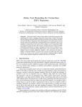
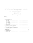
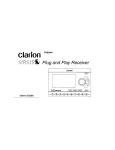
700A/B KEYBOARD ILLUSTRATION
SEARCH
STEP
0
MACHINE
ERROR
0
Section I
Introduction
SECTION I
INTRODUCTION
•
The Wang 700 is the ultimate solution to many calculating needs. Simple or complex
calculations can be done right at the desk. The 700 keyboard is extremely simple to
operate. Once the fundamental operations have been mastered, programming the 700 is
easy.
The Wang 700 is a self-contained programmable electronic calculator constructed with
integrated circuits on snap-in replaceable printed circuit modules. The 700 is composed of
three basic elements:
1. The Central Processing Unit
2. Read-Only Memory
3. Core Memory
The Central Processing Unit (CPU) is the hardware which performs the arithmetic
operations. The Read-Only Memory guides the CPU in all its operations. In effect, the Read
Only Memory is "the brains" of the Wang 700. It directs all arithmetic and logical operations
on the 700 and has been programmed to perform all the functions found on the 67 keys
of the 700 keyboard.
The 700 Core Memory is organized into 121 or 122 data registers; plus a nixie display of
the two work registers X and Y; 120 registers can be used for data storage or program
storage. All user programs are executed from core memory. The trig functions are also
executed from core memory.
Section II explains the modes of operation on the 700, as well as the five non-programmable keys; discusses the dual nixie-type display readout and the basic arithmetic
operations; explains direct and indirect addressing of the data storage registers; explains
the RECALL RESIDUE key _. a unique Wang feature that makes double-precision
arithmetic a simple operation on the 700.
The usefulness of the Wang 700 comes from its programming capabilities. A program is
simply a logical sequence of steps which the calculator can perform automatically over and
over again on different variables. If the calculation is to be performed only once, it probably
is simple enough to do it manually on the keyboard. However, if the same calculations are
to be done repeatedly, it is beneficial to record and save the steps of the calculation in the
form of a program and let the calculator perform these repeated operations. The program
is loaded into core and executed from core. Programs can also be stored on magnetic tape
for later use.
Sections III, IV, V, VI, and VII discuss various techniques to use in programming the
Wang 700. They explain how to introduce a program into core memory and how to save it
for later use on tape cassettes. Also, they explain how several parts of a program can share
the same part of core memory. Section VIII discusses the TRIG functions of the Wang
1-1
Section I
Introduction
INTRODUCTION
700. Section IX gives an example of a 700 Program and further illustrates the concept of
indirect addressing. Section X contains warranty, service, and maintenance information.
An appendix is included in this manual which covers typing conventions and contains an
index to help the user locate with ease certain items of interest.
700A -7008
PROGRAM
STEPS
. REGISTERS
700A
960
000-119
120-121 * (Scratch Pad Only)
2 Level subroutine
Drives 701 output writer
700B
960
000-119
120* (Storage Only)
5 Level subroutine
Drives 701 Output writer
702 Plotter
*The 700A register 121 and the 700B register 120 may be used as scratch pads only if subroutine 00-00 thru 01-15 are not accessed. When these subroutines are called upon the Y
register is automatically stored in these registers.
1-2
Section II
Explanation of Keys
SECTION II
EXPLANATION OF KEYS
MODES OF OPERATION
RUN
LEARN
LEARN
PRINT
LIST
PROGRAM
I •••
0000
!lflllll
o
0
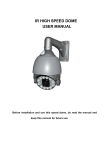
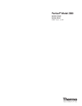
The 700 has four different modes of operation. The four lock-in switches located above the
toggle switches on the 700 keyboard are used to put the 700 into a certain mode of
operation.
RUN MODE
The RUN MODE is used for most 700 operations. All keyboard calculations are done in
the RUN MODE. In fact, practically all operations except introducing a program into core
memory from the keyboard are performed on the 700 in the RUN MODE.
LEARN MODE
The 700 is put into LEARN MODE when a program is to be written into core. Every
programmable key which is indexed while the 700 is in LEARN MODE is "learned" or
recorded in core. In LEARN MODE the Y-Register is blanked and the X-Register displays
the program step number and the program code stored at that step.
LEARN-PRINT MODE
The LEARN-PRINT MODE and the LIST PROGRAM MODE are used only when the
output writer is available. In the LEARN-PRINT MODE,each key indexed is "learned" into
core and is also listed Or the output writer. As each key is indexed, the program step
number and the program code of the key is listed on the output writer, giving the user a
hard copy of his program as he writes it!
2-1
Section II
Explanation of Kevs
LIST-PROGRAM MODE
When the 700 is put in the LIST-PROGRAM MODE and the GO key is depressed, it
automatically lists the program steps and program code in increments of 100 steps until
it encounters an END PROGRAM code. The LEARN-PRINT and LIST-PROGRAM modes
are discussed in greater detail in the 70 1 OUTPUT WRITER MANUAL.
TURNING THE 700 ON
The procedure for turning the 700 on consists of three steps:
1. Turn power switch ON.
2. Index PRIME to initialize the system.
3. Select mode of operation. (In most instances the R UN mode will be selected.
Depress R UN button.)
The Wang 700 is now in RUN MODE ready to perform your calculations.
NON PROGRAMMABLE KEYS
Because of their function, there are five keys which cannot be programmed on the Wang
700. Each of these commands is discussed briefly in this section. All of their functions and
uses will become clear after reading the entire manual.
The five non programmable keys on the 700 are:
PRIME
DODD
I
II
II
II
VERIFY
PROG
I
0
0000
0
EJ
G
SET
PC .
RECORD
PROG
STEP
PRIME
,,
The PRIME key initializes the 700 system and should always be depressed when the
700 is first turned on. It also performs the following operations:
1. Clears V-Register to zero.
2. Clears X-Register to zero.
3. Sets the program counter to Step 000.
4. Resets program-error and machine-error indicators.
2-2
Section /I
Explanation of Keys
The PRIME key should be depressed when the 700 is first turned on.
NOTE
The PRIME key should not be depressed when any operation is being executed. If
the program is to be stopped during execution, the STEP key should be used. This
will stop the program after the current step is executed. Also indexing the PRIME
key when RECORD PROGRAM or LOAD PROGRAM commands are being
executed will cause difficulty with the tape. If the PRIME key is indexed
accidentally during a RECORD PROGRAM or LOAD PROGRAM operation, the
operation will be terminated immediately. However, the tape should be rewound
before executing any other tape operations.
PROGRAM COUNTER AND SET PC
The program counter or PC is a counter which counts from 000 to 959. It indicates which
program step is about to be executed. At all times, it always points to the next program
step. Thus, when the machine is performing step 108, the PC is already on step 109.
The SET PC key allows the user to address and set the program counter with the next
three keystrokes.
SET PC 018
This instruction sets the program counter to program step number 018. To set the program
counter requires four keystrokes: SET PC followed by three numeric keys. PRIME automatically sets the program counter to step number 000.
STEP
The STEP key allows the user to step through his program one step at a time. If the
program is running when the STEP key is indexed, the program stops at the step it is about
to execute. In the RUN MODE, depressing the STEP key will cause the 700 to perform the
next step in the program. Each time the STEP key is indexed, the next program step will be
executed.
The GO key will take the 700 out of the stepping mode and put it in the continuous
mode executing the remaining steps in the program until a STOP command is encountered.
NOTE
In any 2-step command such as DIRECT ADDRESSING and WRITE ALPHA
commands, the GO key should not be depressed in the middle of the 2-step
command. The entire 2-step command should be executed in step mode before
switching to the continuous mode.
This stepping feature is of tremendous value for debugging programs. The programmer
can step through his program and locate his difficulty immediately. By switching to LEARN
2-3
Section II
Explanation of Keys
MODE he can see the step number and the code of the operation he is about to execute.
When stepping through a program in LEARN MODE, the program step number (the PC) and
the program code of the operation is displayed in the X-Register. However, in LEARN
MODE the operation is not executed.
VERIFY PROGRAM
The VERIFY PROGRAM key decimally adds the high-order and low-order digits of the
program codes in core beginning at step 000 until it encounters an END PROGRAM code.
The sum is displayed in the right-most digits of the mantissa of the X-Register.
EXAMPLE
STEP #
000
001
002
003
004
KEY
MARK
0700
x2
CODE
0408
0700
0713
STOP
END PROG
0515
0512
If this program is located in core and the VERIFY
PROGRAM key is depressed the sum displayed in
X is 59.
04
08
07
00
07
13
05
15
-
59
After performing this operation, the PC is set at the step where the END PROGRAM
command is located. (Step 004 in this example.) Notice the code for END PROGRAM is
not added into the sum generated by the VERIFY PROGRAM key.
RECORD PROGRAM
This key transfers a program from core to magnetic tape. The PC is set to a specific
step and the program steps starting at this step are transferred to the tape until an END
PROGRAM command is reached. The END PROGRAM command is the last step transferred to the tape. After transferring the program to tape, the PC is set to where it was
originally set (i.e., the first program step to be transferred to the tape).
The five keys, PRIME, SET PC, VERIFY PROGRAM, RECORD PROGRAM and
STEP are the only keys on the 700 which cannot be used in a program. Therefore, when
any of these keys are indexed it doesn't matter whether the machine is in LEARN or RUN
MODE.
THE DISPLAY
The display consists of two work registers, X and Y. Both the X and Y Registers are
displayed simultaneously by easily readable half-inch nixie-type tubes. Each register has a +
sign and twelve digit mantissa followed by a two-digit exponent with a range of -99 to +99.
2·4
Section /I
Explanation of Keys
XXXXXXXXXXXX
+ . XXXXXXXXXXXX
\
I
mantissa
I
floating decimal
sign of mantissa
+.
X X
(Y-Register)
+ X X
(X-Register)
\
'exponent
sign of exponent
+
For numbers in the range .1 ~ INI < 1 000000000, the decimal point retains its natural
position. When a number lies outside this range, the decimal automatically relocates to the
extreme left, and the exponent of the power of lOis indicated correctly in modified
scientific notation. This property will become clear after a few minutes familiarization with
the keyboard.
(A few numbers and how they appear in the display are given below.)
X-REGISTER
The keys 0, 1, 2, . . . 9 and decimal point (.) are used for entering a number into the
X-Register. The SETEXP key is used to set the exponent value of X. The CH SIGN key
changes the algebraic sign of the mantissa or exponent of X.
Indexing a number into the 700 keyboard is as simple as writing the number down on
paper. The normal sequence of steps is to key in the mantissa followed by the SETEXP
key and the value of the exponent.
ENTERING A NUMBER
Index the following few numbers on the 700 keyboard. After indexing the number into
the X-Register. move it to the Y-Register by depressing the t key.
NUMBER
21
a)
.152 x 10
b)
6.62517x 10 -27
c)
-2534.5
SEQUENCE OF STEPS
DISPLAY
.
5
2
SETEXP
2
1
t
1
-- --7 SETEXP CHS 6 6 2 5 1t
2 62 534 -. 5 CHS
t
-Or
d)
.0075
.152000000000 + 21
.662517000000-26
- 2534.50000000
2 5 3 4 5 CHS SETEXP 4 t
.0
5t
-0
-7
-+.750000000000-02
Or
2 7 5 SETEXP CHS t
--
Index c and d both ways. Does the display appear differently? Notice example b. Why is 26
entered as the value of the exponent?
SET EXP
The SETEXP key is used to set the exponent value of X with the next two successive
keystrokes. The SETEXP key automatically aligns the decimal point in the left-most
position of the X-Register: however, it does not blank out the mantissa. This allows us to
change the value of the exponent of a number without having to key in the entire number
agam.
•
2-5
Section II
Explanation of Keys
EXAMPLE
Index 1.75 x 10 23
Suppose the following sequence of steps is used:
1 . 7 5 SETEXP 2 3
Notice what happens to the decimal point when the SETEXP key is indexed. It is not
necessary to index the decimal point, as the SETEXP key automatically aligns it in the left
most position. The value of the exponent will also have to be indexed correctly. If the
number is in proper scientific notation, the value of the exponent is simply increased by 1.
Thus, the correct sequence of steps would be:
CLEAR X 1 7 5 SETEXP 2 4
All numbers indexed after the SETEXP key simply changes the value of the exponent. Since
the range of the exponent is -99 to +99, normally only I or 2 numbers are indexed after
the SETEXP key. However, if more than 2 numbers are indexed, the exponent takes on the
value of the last 2 numbers entered.
EXAMPLE
If the following sequence of steps is performed:
1. 1 2 SETEXP 2 3 4, the value of the exponent is 34.
2. For SETEXP CHS 3 57, the value of the exponent is -57.
3. For SETEXP 5 0 2, the value of the exponent should be 2. However, on the
display the exponent would be blanked out and the decimal point would assume
its natural position.
The 700 will remain in the SETEXP mode until a non numeric key or the decimal point key
is depressed.
V-REGISTER
The Y-Register is another work register used in conjunction with the X-Register for basic
arithmetic operations and data transfers. A number in the X-Register can easily be transferred to the Y-Register by indexing the t key or ~ t key.
KEYSTROKE
OPERATION
+
Clears X-Register
X into Y, X unchanged
Y into X, Y unchanged
X and Y exchanged
Y+X into Y, X unchanged
x
Y-X into Y, X unchanged
Yx X into Y, X unchanged
CLEAR X
f
~
U
2-6
Section 1/
Explanation of Keys
Y+X into Y, X unchanged
•
•
Absolute value of X into X, Y unchanged
!XI
INTX
Disregards decimal part of number in X and
puts integer part of number in X, Y unchanged
l/X
1/X into X, Y unchanged
x 2 into X, Y unchanged
vx
v'X into X, Y unchanged
LOGloX
lOx
LOG lo X into X, Y unchanged
LOGeX
x
e
rr
LOGeX into X, Y unchanged
eX into X, Y unchanged
lOx into X, Y unchanged
rr into X, Y unchanged
Step through the following examples to familiarize yourself with these keyboard
operations.
EXAMPLE 1. Calculate.083+ 17.86+32.2= +50.1430000000
1. PRIME
2.·.083~
3. 1 7. 8 6 +
4.3 2 . 2 + (Answer in Y, 32.2 in X)
EXAMPLE 2. Calculate (5)2 - (20)2 + (1/15)2 +V'70 = - 366.628955291
1. CLEAR X
2
2. 5 x
3.20 x 2 4. 1 5 l/x x 2 +
5.70
+
(Answer in Y,v'70 in X)
t
vx
EXAMPLE 3. Calculate 51 x 6.2 = + 62.0119219307
y'26'
t
1.51
2. 6 . 2 x
3. 2 6-vx +
(Answer in Y,v126 in X)
EXAMPLE 4. A=rrr2
t
1.51
2. 2 6
+
3.6 . 2 x
(Answer in Y, 6.2 in X)
vx
r=.568x 10- 6 = +.101355318827-11
1.5 6 8 SETEXP 6 CHS
rr
2. x 2
3. X
(Answer in Y, rr in X)
t
2-7
Section II
Explanation of Keys
EXAMPLE 5. Calculate (12.8)?/3
1. 1
2.
3.3
4.
t
=
+ 383.256852976
2 . 8 LOGeX
7 x
1. 1 2 . 8 LOG! 0 X
2.' 7 x
or
+
3.3+
4. ~ lOX (Answer in X)
t eX (Answer in X)
EXAMPLE 6. Reduce t~e angle 865 0 to an equivalent angle less than 360 0 .
Formula 865 - INT ~865'; 360 = equivalent (145)
360
360
value
'.
/
1. 865 t
2.3 6 0 +
3. tINT (X)
-
4.5.3 6 0 x (Answer in Y, 360 in X)
EXAMPLE 7. Calculate the following:
a. c = 2 T( r where r = .347 X 10- 5 = .21802 .. xlO- 4
b. M = 90 + 87 + 68 + 77
= 80.5
4
c. y'"M +
1 where M is the answer of 7 (b)
,
\
,
,
y'M
Answer = 8.984 ...
t
Hint:
Use + key
d. e 5 .3 + 10 5 . 7 + T(2 = 501397 .4 ...
e. Log (-. 2) What happens? Why? PRIME and find
vC3. What happens? Why?
;i
PROGRAM-ERROR INDICATOR
.
•
There are two lights located to the right of the Special Function Keys on the 700
keyboard. These two lights are used as error indicators. The one on the right indicates
MACHINE ERROR; the one on the left PROGRAM ERROR. The MACHINE ERROR
INDICATOR is discussed later.
The PROGRAM ERROR INDICATOR is turned on whenever an illegal operation is
performed (i.e., taking the logarithm or square root of a negative number, or dividing by
zero). Also, if a calculated result is greater than 10 99 , the PROGRAM ERROR INDICATOR
will be turned on. Whenever the indicator is on, the arithmetic sign of the X-Register
also flashes.
OPERATIONS WHICH TURN PROGRAM ERROR INDICATOR ON
Calculated result greater than 1099
Division by 0
(Overflow condition)
y:::x
LOG!
oX
where x< 0
2·8
Section II
Explanation of Keys
Log e where x< 0
Searching Non-Existent Flag (See page 4-3).
Addressing An Illegal Data Register (Any Register Greater than 121)
Program Overlaps Core (See BYPASSING PROGRAM BLOCKS page 6-8)
Program Block is Missing An END PROGRAM Instruction (See
Definition of PROGRAM BLOCK (page 6-4)
The PRIME key is used to turn the PROGRAM ERROR INDICATOR off. In programIlling, a SKIP IF ERROR command is available to test for this condition. Performing this
il'st will also turn the indicator off.
DATA STORAGE REGISTERS
[n addition to the X and Y work registers, the Wang 700 has up to 122 storage registers.
I ':ach register has a 12-digit mantissa with sign and a two-digit exponent with sign. The
registers are numbered consecutively from 000 to 121 and can be addressed both directly
;Ind indirectly for maximum convenience. Numbers are stored from and recalled to the XRegister. Each register can be used to add, subtract, multiply and divide. Any number in
storage can be exchanged or swapped with any number in the X-Register.
DIRECT ADDRESSING
Direct addressing of registers requires a two-step command. The first keystroke indicates
lile operation (i.e., to Store, Recall, Add, Subtract, Multiply, Divide, or Exchange). The
second keystroke indicates the register in which the operation is to be performed. To store a
nllmber, simply index the control key STORE DIRECT followed by a second keystroke
Identifying the register number.
TOGGLE SWITCHES AND SPECIAL FUNCTION KEYS
Eqch register is represented by a combination of toggle switch settings and special
III nction keys.
0000
00
01
02
03
04
05
06
07
08
09
10
11
12
80402010
DODD
It
••••
o
2-9
0
13
14
15
.... -_
~--
-"
..
''-
"
.. --
'
Section II
Explanation of Keys
The toggle switches are set to the OFF (down) position. When the toggle switches are
in the down position, the special function keys designate the registers 000 to 0 15. The 4
toggle switches are labeled 80, 40, 20 and 10. When one of these toggle switches is switched
to the ON (up) position and a special function key is indexed, the register designated is the
sum of the values of the toggle switches and the special function key.
(1)
:;:::::;::::::::::
0080
00
01
02
03
Wf
05
06
07
08
10
09
11
12
13
14
15
;.:.;.:-:.:.:<.:.
80402010
DODD
IltllllJ
••••
o
0
Depressing the special function key 04 while switch setting (20) is flicked ON designates
register 24 (20 + 4).
(2)
BoBO
80402010
gg
..................
01
02
03
04
05
06
09
••.•· .0
.••. :.1.................. 08
12
11
10
13
14
15
_---L_-'--_I....-..--L_--l.-_~=_---L_-'--_I....-__l._----L_..l.-----'L---'
DODD
••••
.
I
~
,
Ii
II
,
.
II
•
•
a
.....
-~...,
o
0
Notice the toggle switch setting. When the 07 key is indexed the register designated is 117
(80 + 20 + 10 + 7). When the 00 key is indexed the register designated is 110 (80 + 20 + 10
+ 0).
2-10
Section /I
Explanation of Keys
(3) Designate Register 32 in two different ways:
oong
00
01
80402010
:j!,III!
03
05
04
06
07
0000
08
09
11
10
:::J £=Ji
11
CI
12
13
14
15
1
••••
o
0
One way of doing this would be to set toggle switches 20 and 10 to the ON (up) position
and press the special function key 02.
Another way is the following:
oogo
00
01
02
04
03
05
07
06
08
09
10
i~~[·i:1
11
80402010
••••
DODD
. .
......
.
~
I
- .
..',.,
I[
13
14
15
Il~
II
.
.
o
0
J:'
- ,,,.
_.' ';~ ,
-,< '-
Set toggle switch 20 in the up position and press the 12 key. Notice both combinations
20 + 10 + 2 and 20 + 12 designate register 32. Thus, different combinations of toggle switch
settings and special function keys can be used to identify a particular register. However. in
2-11
Section II
Explanation of Keys
LEARN MODE the program code designating Register 32 would be 0302 or 0212, depending on which method was used.
STORE DIRECT
To store a number in a register, simply index the number into the X-Register, press the
STORE DIRECT key followed by the register number.
EXAMPLE 1:
Store 1r 2 into register 14
* Toggle switches down
Index 1r x 2 STORE DIRECT 14
1r 2 is now stored in register 14 and is still
displayed in the X-Register.
EXAMPLE 2:
Store .57 x 10
18
into Register 32
*Toggle switches 20 and 10 UP
Index ---5 7 SETEXP 18
STORE DIRECT 02
.57 X 10 18 is now stored in Register 32 and
is still displayed in X.
* NOTE
For problems requiring less than 17 storage registers and for general usage, the
toggle switches are kept in the OFF (down) position and the Special Function
Keys are used to address Registers 000 to 015.
RECALL DIRECT
i
RECALL DIRECT recalls the number from the designated register into the X-Register.
The number appears in the X-Register and also remains in the storage register. The sequence
of steps to follow is the same as with STORE DIRECT.
EXAMPLE:
Recall1r 2 from register 14
Index RECALL DIRECT 14
I
1r 2 appears in the X-Register and is still
in storage register 14.
2·12
Section 1/
Explanation of Keys
~
-.....
DIRECT,
The -: DIRECT key is a handy command which allows the operator to exchange
a number in the X-Register with a number in any of the storage registers. The command
simply swaps the values of the X-Register and the internal register. Again the sequence of
steps to follow is -: DIRECT followed by the desired register.
EXAMPLE:
Suppose 27.8 is in the X-Register and 1f2 is
in Register 14. To store 27.8 in Register 14 and
reca1l1f 2 to the X-Register in one operation:
Index ~ DIRECT 14
What happens if the same operation is performed again?
ADD, SUBTRACT, MULTIPLY, AND DIVIDE DIRECT (The X and V Registers Remain Unchanged.)
In addition to storing a l2-digit mantissa and a 2-digit exponent, the registers can be
lIsed as accumulators to add, subtract, multiply and divide. With each of these operations
t he result is stored in the designated register and the X-Register and Y-Register remain
ullchanged.
The four arithmetic operations are'•
+DIRECT
-DIRECT
XDIRECT
-:-DIRECT
Adds number in X-REGISTER to value stored in register designated by
next keystroke. The X and Y Registers remain unchanged.
Subtracts number In X-REGISTER from value stored In register designated
by next keystroke. The X and Y Registers remain unchanged.
Multiplies number in X-REGISTER by value stored in register designated
by next keystroke. The X and Y Registers remain unchanged.
Divides number in X-REGISTER into number stored in register designated
by next keystroke. The X and Y Registers remain unchanged.
A simple example will illustrate how each of these commands works.
EXAMPLE:
Perform the following in Register 001
(13 x2) + 4
-3=7
3
1 3 STORE DIRECT 01
1.
--
2.
2
X
DIRECT
01
-
3.
4 + DIRECT 01
-
Places 13 in Register 01
and the X-Register
This sequence of steps
places the product equal
to 26 in Register Oland
2 remains unchanged in the X-Register.
Adds 4 to the Answer.
30 is now in Register 01,
4 is in X-Register.
2-13
Section II
Explanation of Keys
4.
3 -;.-DIRECT 01
-
5.
- DIRECT 01
6.
RECALL DIRECT 01
Divides result by 3
putting lOin Register 01,
3 remains in X-Register.
Since 3 is in X when
the command is given,
3 is subtracted from
10 putting 7 in
Register 01, 3 in X-Register.
Recalls final answer
to X. = 7
The fact that the result is put in the storage register rather than the X-Register can be
extremely useful if we are using a constant multiplier or divisor.
INDIRECT ADDRESSING
In addition to providing direct access to the internal storage registers, the Wang 700
offers an indirect mode of address. Both display registers are utilized for indirect addressing.
The Y-Register designates the register being addressed. As with direct addressing, the
X-Register is used as the work register. The command is performed on the number in X and
the result is placed in the internal storage register.
Indirect addressing is a valuable programming tool for saving program steps, especially in
repetitive matrix-type operations. Remember, indirect addressing requires only one step the operation itself. The register on which the operation is performed is identified by the
number in Y.
INDIRECT KEYS
The indirect commands are identical to those used in direct addressing. They consist of
the following:
OPERATION
KEY
Stores number in X into Register
designated by number in Y.
Recalls number to X from register
designated in Y. Number also remains
in register.
Swaps number in X with number in
register designated by Y.
Adds number in X to number in register
designated in Y. The sum is placed in
internal register. Number in X remains
unchanged.
STORE INDIRECT
RECALL INDIRECT
:>
,
INDIRECT
+ INDIRECT
2-14
Section /I
Explanation of Keys
Subtracts number in X from number in
register designated in Y. The
difference is placed in internal
register. Number in X remains
unchanged.
Multiplies number in X by number in
register designated in Y. The product
is placed in internal register.
Number in X remains unchanged.
Divides number in X into number in
register designated in Y. The quotient
is placed in internal register. Number
in X remains unchanged.
- INDIRECT
X INDIRECT
-;- INDIRECT
The following example illustrates how each of these commands would be used.
Example
Perform the following in Register 002 using Indirect mode of address.
7(5.8)-7.2 2+ 3 = 126.951111110
3
KEY
,
OPERATION
2
t
--
Places the register number in Y (The
register number is usually computed
in the program)
7
ST
INDIR
-
Stores 7 in register 002. The value is
now in both register 002 and the X
Register.
5 . 8 X INDIR
Multiplies the value (7) in Register
002 by 5.8,putting the result in 002
and 5.8 remaining in X.
7
.
2
INDIR
---
Subtract 7.2 from the value in Register
002 and places result in Register 002.
7.2 remains in X.
3 -;- INDIR
Divides the value in Register 002 by 3.
The result is put in Register 002 and
3 remains in X.
-------
~
~INDIR
Exchanges 7(5.8) - 7.2 in Register 002
3
with 3 in the X-Register.
Squares the value in X.
2-15
Section II
Explanation of Keys
,< "
•
+ INDIR
Adds
RECALL INDIR
Recalls final answer = 126.951111110
7(5.8) - 7.2 2 to 3 in Register
3
002. The result is placed in Register
002 and 7(5.8) - 7.2 2 remains in X.
3
ADVANTAGES OF INDIRECT ADDRESSING
Two advantages of the indirect mode of addressing are:
1. It requires only one keystroke to perform the indicated operation.
2. By ,constructing a loop, a given program step sequence can operate on many different
setll of registers. A saving of many program steps can result from this technique.
~.o:
·
-;,.,
<
Figure L is a simple program which illustrates the advantage of indirect addressing. The
program stored
0
in
the
first
100
registers.
Using
direct
access
a
minimum
of
200
steps
.".:
would betequired. (Two keystrokes per register - STORE DIRECT followed by each
register nufnber.) In contrast, this program requires only 13 steps to accomplish the same
thing. A savings of 187 steps!
, .e.
-
,
FIGURE 1
·,.'
OPERATING PROCEDURE'• PRIME GO
•
.,
"
•
,.
"~
.,..
·
·
~.
· or·
-
~.
~
..
...
,-~
-"'~
~,
.
'
'...,
.'.
"
·
.}
.'.).
~k' .
·.,......-
".-
STEP
KEY
CODE
000
1
2
3
4
5
6
7
8
9
10
11
12
MARK
0700
0
STIND
1
0408
0700
0700
0504
0701
0600
0701
0700
0700
0509
0407
0700
0515
+
1
0
0
SKIP Y=X
SEARCH
0700
STOP
.
:t.. ~
--.
,-"
:;.::-'
RECALL RESIDUE
The RECALL RESIDUE key is a unique Wang 700 feature which can be of great value
to users who need greater than 12 digit accuracy. The RECALL RESIDUE key gives the
2-16
Section 11
Explanation of Keys
user the option of double precision arithmetic for addition, subtraction, multiplication, and
division performed in any of the storage registers or the X and Y registers. By indexing
the RECALL RESIDUE key directly after performing one of these operations, another
12 digits of accuracy is acquired.
ADDITION, SUBTRACTION, MULTIPLICATION
When the RECALL RESIDUE key is indexed after performing an addition, subtraction
or multiplication, a residue is displayed in the X-Register, which if added to the first 12
digits of the result, gives an additional 12 digits of accuracy. Examples are given to show
how the RECALL RESIDUE key is used for addition, subtraction, and multiplication.
EXAMPLE 1:
ADD
5024873058.28
OPERATION
ON 700
DISPLAY
5024873058.28
------------t
"+5024873058.28
+6.8520987
-
+ 6.8520987
5024873065.1320987
.
6.8520987
- - - - - - - -"+.502487306513 +10
-+
•
~6.8520927
RESIDUE
+.502487306513 +10
+.209870000000 -02
By indexing the RECALL RESIDUE key, the significant digits which would ordinarily
be lost in the shifting process are retained. The final result is always the algebraic sum of
the values displayed.
In subtraction, however, the residue might be opposite in sign to the answer. This should
not cause any difficulty since the residue is always algebraically added to the result.
EXAMPLE 2:
SUBTRACT
OPERATION
ON 700
DISPLAY
,.
.
5024873058.28
-5024873058.28
- - - - - - - - -- - t
-
- 6.8520987
5024873051.4279013
6.8520987
---------
"
45024873058.28
~6.8520987
tf..502487305143 + 10
~6.8520987
2-17
'.
Section II
Explanation of Keys
RESIDUE
+.502487305143 +10
-.209870000000 -02
In this example, the residue is opposite in sign to the result. If these two numbers aIT
added together, the correct result is generated. An easy way of performing this addition is to
decrease the 12th digit of the result by 1 (.502487305143 becomes .50248730512),
subtract each digit of the residue from 9 so .20987 becomes. 79012, and add 1 to the last
significant digit (.79013).
Multiplication works the same way as addition.
EXAMPLE 3:
OPERATION
ON 700
MULTIPLY
3 141 5.9254998
-------------
31415.9254998
.728645297326
DISPLAY
+31415.9254998
+.728645297326
t
.728645297326
-------------
•
The answer IS
x
-
22891.0663765732361535348
RESIDUE
/+22891.0663764
+.728645297326
/+22891.0663765
+.732361535348. -07
~
I
~
~
The first twelve digits of the product are in Y; the last 12 digits are in X.
DIVISION
Using the RECALL RESIDUE key in division is slightly different from addition,
subtraction, and multiplication. In division, indexing the RECALL RESIDUE key gives
us a remainder. Using this remainder and the original divisor, 12 more digits of accuracy can
be obtained by performing the division again. Study the following example illustrating the
technique:
2-18
f?
,'i
"
Section II
Explanation of Keys
I
\;\MPLE 4:
DIVIDE 22
7
I
3.14285714285
/ /220000000
OPERATION
ON 700
22
--
t-
21
10
7
30
28
20
14
60
56
40
35
50
DISPLAY
/+22.000000000
+7
7
•
•
-
+3.14285714285
+7.00000000000./
RESIDUE
"+3.14285714285
~.500000000000
-11
49
10
7
30
28
20
14
60
56
40
35
.___lII
Remainder
The +.500000000000 - 11 displayed in X after the RECALL RESIDUE key is pressed
indicates a remainder of 5 after the first 12 digits of the quotient are generated. Notice the
proper decimal position is retained (i.e., .5 x 10- 11 ). Since the decimal position is retained
automatically, the original divisor should be expressed with the decimal point in the left
most position and an exponent value of 0 before performing the second division. Thus, .7 is
divided into the remainder .5 xl 0-11 and 12 more digits of the quotient are generated. To
preserve the first 12 digits of the quotient, the second division is performed in Register 000.
2-19
Section II
Explanation of Keys
Since the remainder is now in X
STDIR 00
7 SETEXP* 7DIR 00
RE DIR 00
*This command automatically aligns the decimal point and exponential
value of the divisor.
Read .714285714285 - 11 in the X-Register which if added to 3.14285714285 yields
24 digit accuracy for 22/7. If greater accuracy is desired, simply touch the RECALL
RESIDUE key to obtain the remainder (.5000000000000 - 23) and repeat the process.
This example illustrates the fact that the RECALL RESIDUE key performs the same
function when any of the 120 internal registers are used to add, subtract, multiply and
divide. The RECALL RESIDUE key is NOT limited to use solely with the X and Y registers.
IT SHOULD ALSO BE NOTED THAT THE RESIDUE MUST BE SAVED AFTER EACH
OPERAnON IF IT IS TO BE USED IN FURTHER CALCULAnONS.
WRITE COMMANDS
The 701 Output Writer provides the user with completely formatted alpha-numeric
output of his calculated results.
NUMERIC output consists of a two-step command. The WRITE key followed by a
format command will print the contents of the X-Register.
The format command specifies the number of digits to be printed out before and after
the decimal point
EXAMPLE
WRITE
02
~~.
03
-.
The LOW ORDER digit
of the code specifies
the number of digits
after the decimal point.
The HIGH ORDER digit
of the code specifies
the number of digits
before the decimal point.
'.
The above command would print two digits before the decimal point arid three digits
after the decimal point.
An option to always print in modified scientific notation is available.
2·20
Section /I
Explanation of Keys
EXAMPLE
Display:
+.12345678123 - 40
Command:
WRITE
0015
Output will appear as:
.123456789l23ex - 40
ALPHABETIC output can be printed under program control by using the WRITE
ALPHA command. Indexing the WRITE ALPHA key places the 700 in alpha mode so that
:i1pha characters can be printed. The END ALPHA command takes the 700 out of alpha
11l0de.
EXAMPLE
(Places 700 in alpha mode)
WRITE ALPHA
H
E
L
L -
o-
0101
0205
0109
0109
0209
•
(Takes the 700 out of alpha mode)
END ALPHA
The above example would print the word '"HELLO."
Other control commands such as shifting to upper and lower case, carriage return, line
feed, spacing, backspace, and tabulation are all available on the Output Writer. All these
features are discussed in the 701 OUTPUT WRITER MANUAL.
GROUP1-GROUP2
These two keys are reserved for addressing optional peripheral equipment.
2-21
Section 11/
Programming
SECTION III
PROGRAMMING
CODING
All programmed operations are represented by a 4-digit code. A list of the keyboard
operations and their respective codes is given below:
700 PROGRAM CODES
CODE
KEY
CODE
KEY
0400
+ DIRECT
0600
+
0401
- DIRECT
0601
-
0402
x DIRECT
0602
x
0403
7 DIRECT
0603
-••
0404
STORE DIRECT
0604
t
0405
RECALL 01 RECT
0605
t
0406
~DIRECT
0606
(j
0407
SEARCH
0607
Ix I
0408
MARK
0608
INTEGER X
0409
GROUPl
0609
'IT
0410
GROUP2
0610
L09! oX
0411
WRITE
0611
L0geX
0412
WRITE ALPHA
0612
VX
0413
END ALPHA
0613
lOx
0414
STORE Y *
0614
eX
0415
RECALL Y *
0615
l/x
0500
+ INDIR
0700
0
0501
- INDIR
0701
1
0502
x INDIR
0702
2
0503
7 INDI R
0703
3
0504
STORE INDIR
0704
4
0505
RECALL INDI R
0705
5
0506
C'INDIR
0706
6
0507
SKI P if Y;;;" X
0707
7
*ENTERED BY TOGGLE SWITCH SETTING
3·1
Section III
Programming
0508
.0509
,I
I
I)
SKIPifY<X
0708
8
SKIP if Y = X
0709
9
0510
0511
0512
0513
SKIP if ERROR
SET EXP
0514
0515
GO
0710
0711
0712
0713
0714
0715
RETURN
END PROG
LOAD PROG
STOP
CHANGE SIGN
DECIMAL POINT
X
2
RECALL RESIDUE
CLEAR X
The four-digit code consists of 2 halves: a high-order 2-digit number and a low-order
2-digit number.
x
!
X
X X
-------LOW
HIGH
ORDER ORDER
Each of these halves can assume the values 00, 01, 02, ... up to 15. Thus there are 16
different high and low-order digits and a total of 16 x 16 = 256 codes.
The 64 codes used in the above table are set aside for the keyboard operations. They
consist of all possible combinations that can occur when the high-order digit assumes the
values 04, 05, 06 and 07 and the low-order digit assumes the values 00 to 15 - a total of 64
codes (16 combinations are in each of the 4 categories).
GENERATING A CODE USING SPECIAL FUNCTION KEYS AND TOGGLE SWITCHES
While this procedure is not recommended for any of the "operation keys," any legal code
can be generated using the toggle switches and the special function keys. The special
function keys are used to define the low-order digit and a combination of toggle switches is
used to define the high order digit.
0000
00
01
02
03
04
05
06
07
08
09
10
11
12
80402010
DODD
••••
o
3-2
0
13
14
15
Section" I
Programming
The toggle switches are labeled 80, 40, 20, and 10 for convenience in selecting the
data storage registers discussed in Section II. THEY CAN ALSO BE VISUALIZED AS
REPRESENTING THE NUMBERS 08, 04, 02,AND 01 FOR THE PURPOSE OF GENERATING THE HIGH-ORDER DIGIT OF ANY LEGAL CODE. When a special function
key is indexed, the operation executed by the calculator is the command whose high-order
digit is defined by the setting of the toggle switches and whose low-order digit is the special
function key indexed.
oDgo
00
01
02
03
04
05
06
07
08
::l~:::\
11
10
09
80402010
DODD
:::::::::I'I
II
13
14
15
II:::::::::::J
••••
o
0
If the toggle switches are set as in the above figure and the special operation key 12 is
indexed, the square root of the number in the X-Register will be generated since the code
for square root is 0612. Naturally, the square root of a number would rarely be found
using this technique, however, this example is included to explain how to generate any of
the 256
codes. This technique
.
- is used most often with the Store Y and Recall Y commands.
•
CORE MEMORY
,~:
,'"
t
~-
,
f-
,
(-
Core Memory is organized into 121 or 122 data registers numbered consecutively from
000 to 121 or 122. Registers 000 - 119 are used for storing either program steps or data.
16 program steps occupy 2 data-storage registers. Register 120 and 121 are used exclusively
for data storage .(700B data register 121 not available.)
As stated previously, each programmed operation is represented by a four-digit code. The
four-digit code consists of two halves: a high-order two-digit number and a low-order
two-digit number.
XX
'-.;-"
.
XX .
v
HIGH
LOW
ORDER ORDER
The program code forV"X is
06
'-.;-"
12
'-.;-"
HIGH
LOW
ORDER ORDER
3-3
II
I:
i i
i1
li
I,• ••'
i j
i i
j j
Section III
Programming
iI i;
'I
,,l, ,l,
;
-'
j
:,1 ,!,
! !
i• •
)
11
i ,
CORE STORAGE
, i
; j
j i
i 1
!
j
REG
NO.
I1
ij
,,: ,j
.;
ij
!I
I ;
• •
i
1
i:
i '
i!
I, :,
! ;,
j;
i ;
000
001
002
003
004
005
i1
Ii
I •
• •
I 1•
•
)i
006
007
I
008
009
I(
;
, ,
I
,,
012
013
8
6
,
016
017
!
j ,
,
018
019
I,
,i :
i
I
,I !'
020
021
!
! :
i;
I
,
j
022
023
024
025
ii
!,
Ii
i :
!
026
027
028
029
030
031
i
i
I;
,, ;
1i
032
033
!'
034
035
036
037
038
039
9
4
4
9
2
8
9
1
2
8
9
6
8
8
0
8
6
4
9
1
1
8
9
5
8
7
9
014
015
!
!
9
5
9
9
4
3
9
2
7
010
011
•
!•
REG
NO.
~
8
4
7
8
3
1
8
1
5
7
9
9
7
8
3
7
6
7
7
5
1
HIGH ORDER
LOW ORDER
8
4
8
8
3
6
8
1
6
8
0
0
7
8
4
7
6
8
7
5
2
J
3
6
040
041
042
043
044
045
046
047
048
049
050
051
REG
NO.
6
3
9
6
2
3
6
0
7
5
9
1
5
7
5
5
5
9
17
5
056
1
057
1
058 4
059 9
5
060 4
061 7
9
062 4
063 6
3
064 4
065 4
7
066 4
067 3
1
068 4
069 1
5
7
2
0
7
1
9
7
0
3
6
8
7
7 070 3
0 071 9
9
4
6 072 3
I;
073 8
8
3
6
074 3
7
075 6
2
7
6
076 3
5
077 5
6
1
6 078 3
4 079 3
0
5
PROGRAM STEP NO.
•
LOW ORDER
5
052
4
053
3
054 5
055 2
7
3
5
6
7
1
6
5
5
HIGH ORDER
PROGRAM STEP NO.
•
3-4
6
3
'080
2
1
081
4
9
6
082 3
0
083 0
8
3
5
084 2
9 085 8
2
7
5
086 2
7
087 7
6
1
5 088 2
6 089 5
0
5
5
090 2
4 09 1 3
4
9
5
092 2
2 093 2
8
3
5
094 2
1
095 0
17
2
4 096 1
9 097 9
6
1
4 098 1
8 099 7
0
5
4
100 1
6
10 1 5
4
9
4 102 1
4 103 4
8
3
4
104 1
HIGH ORDER
3
105 2
LOW ORDER
2
7
4
106 1
1
107 1
6
1
4
108 0
0
109 9
0
5
3 110 0
8 11 1 7
4
9
3 112 0
6 113 6
8
3
3 114 0
5
115 4
2
7
3
116 0
3
117 3
6
1
3 118 0 0 0 0 0 0 0 0 0 0 0 0 0 0 0
2 119 1 1 1 1 1 1 0 0 0 0 0 0 0 0 0
0
5 4 3 2 1 0 9 8 7 6 5 4 3 2 1
PROGRAM STEP NO .
•
3
0
4
2
8
8
2
7
2
2
5
6
2
4
0
2
2
4
2
0
8
1
9
2
1
7
6
1
6
0
1
4
4
1
2
8
1
1
2
0
9
6
0
8
0
0
6
4
0
4
8
0
3
2
0
1
6
0
0
0
Section III
Programming
I~,
'iii)
1
i;
0
I
~/
A Program code step occupies two digits of storage, one digit in each of two adjacent
registers; the high-order digit of a code occupying one register; the low-order digit the othn
register.
Program steps 000 to 015 occupy registers 118 and 119. The following routine to add
2 + 2 is loaded into Registers 118 + 119 as illustrated.
ff·.··
~:::',
'
rj"? "
t~·
<,~'--
~,
STEP
f'-'
5~;::
l/)'
0>.
ltt
000
001
002
003
004
~l,-~-__
~'T
~t:
,c"
"if' '."
•...
0,
~:::
;;;/',
c_ -,
r'
F
KEY
CODE
STOP
END PROG
0702
0604
0600
0515
0512
2
t
+
r:j::
;::. ~\,
•
"
t
FIGURE
1
Registers
118
119
high
order
12 15 00 04 02 low
order
015 014 013 012 011 010 009 008 007 006 005 004 003 002 001 000
05 05 06 06 07
PROGRAM STEP NUMBERS
The high-order digit of the program code is loaded into Register 118, the low-order digit
of the code in Register 119. Each pair of registers can accommodate 16 program steps. The
program steps are numbered 000 to 959. Step 000 is located in Data Registers 119 and
118, Step 959 is located in Data Registers 000 and 001. (See Page 3-4) It shows exactly
what program steps are located in each register. It is advisable to use registers 000, 00 1, 002
003, etc. for data storage and registers 119, 118, 117, etc., for program storage. In this way
data will be stored in one end of core and program operations will be stored in the opposite
end of core.
NUMBER OF REGISTERS OCCUPIED BY A PROGRAM
If a program is 7 steps long, 2 data registers are being utilized for storing the program. If
the program is 35 steps long, 6 data registers are being used for program steps. To determine
how many registers are being utilized:
1. Divide the number of program steps by 16.
2. Round the answer to the next whole number.
Example:
33
16 = 2.0625 becomes 3
3. Multiply the whole number by 2 to find the equivalent number of registers being used.
3-5
Section 11/
Programming
CORE MEMORY
000
001
002
003
+
9
5
9
1I1111111
12 Digit Mantissa + EX
9
4
3
9
2
8
Data
+
t
Program
116
117
118
119
0
3
1
0
1
6
Accommodates
Prog. Steps
016 to 031
0
1
5
0 0 0 0
0 0 0 0
3 2 1 0
Accommodates
Prog. Steps
000 to 015
120
121
7006 (register 121 not available)
•
Program Step Numbers
Example
Program of 88 steps occupies 12 registers
88
16=5.5 -" 6 (2) = 12 registers
See Section V, Page 5-4 (for short program to perform this calculation.)
1
i:
):
ii
I:
F
i
,
I;
"
,!
il
3-6
Section IV
Programming Concepts
SECTION IV
PROGRAMMING CONCEPTS
PROGRAMMING CONCEPTS
To exploit the full programming capability of the 700, a few basic programming concepts
must be discussed. These are the concept of a branch, a subroutine, a loop and a decision.
Usually, the main part of a program advances one step at a time in a linear and
continuous fashion. Each operation is performed consecutively one after the other. A
program to evaluate the polynomial y = 20x 2 + 5x + 7.2 for different values of x would be:
OPERATION
STDIR
REG 00
x2
t
2
o
x
5
XDIR
REG 00
REDIR
REG 00
+
7
•
2
+
CODE·
0404
0000
0713
0604
0702
0700
0602
0705
0402
0000
0405
0000
0600
0707
0712
0702
0600
REMARK
Key in x
20x 2 in y
20x 2 + 5x in y
20x 2 + 5x + 7.2 in y
Notice "the program" is simply the steps the user would perform if he were doing the
calculation manually on the keyboard. However, the program needs some sort of command·
to tell the calculator where to start and where to end its calculation. This is the purpose of
the SEARCH and MARK commands.
4-1
Section IV
Programming Concepts
MARK AND SEARCH COMMANDS
Flags (names or marks) in a program are set by the MARK key followed by a second
keystroke. To set a flag requires 2 keystrokes: MARK followed by any of the 256 legal
codes. Thus, there are 256 different "names" or flags which can be used in a Wang 700
program. For the simple program we have written to evaluate Y = 20x 2 + 5x + 7.2, the
number key 1 is used as a distinguishing flag. Thus, the program is preceded by the 2
keystrokes MARK 1. To end the calculation simply add a STOP command. The complete
program thus becomes:
OPERATION
MARK
1
STDIR
REG 000
x2
t
2
0
x
5
XDIR
REG 00
REDIR
REG 00
+
7
•
2
+
STOP
CODE
0408
0701
0404
0000
0713
0604
0702
0700
0602
0705
0402
0000
0405
0000
0600
0707
0712
0702
0600
0515
REMARK
Flags tell the 700 where to start its calculations. They indicate the destination of a
SEARCH command. In the SEARCH command, 2 keystrokes are required: SEARCH
followed by a second keystroke which identifies the flag or mark to find. Thus, the
operating procedure for the above program would be:
Key X; SEARCH 1
and the operations between MARK 1 and the STOP command would be executed in
sequence.
4-2
Section IV
Programming Concepts
Generally, the numeric keys 0, 1, 2, . . . 9 are used as flags or markers for starting
general programs. However, any programmable key on the 700 keyboard can be used as a
name or marker. A program can start with a MARK eX and to locate this mark, simply
SEARCH eX. It should be clear that when the MARK and SEARCH keys are indexed the
calculator interprets the next· keystroke as a name or flag and not as any other type of
operation. When a SEARCH X command is given the 700 searches through core to locate
the designated marker. If on scanning core it doesn't find the mark, the program stops and
the PROGRAM ERROR INDICATOR goes on indicating there is no such mark in core.
MARK
The program for evaluating the polynomial follows a linear sequence of
steps. The program executes step 000,
then 001, then 002, and so on through
to the last step. However, the Wang 700
does not have to follow a linear sequence
of steps. ltis possihle for the 700 to
start executing commands from step 025
and go through to step 052, then jump
to step 075 ignoring all· the commands
between step 052 and 075. To break out
of a linear sequence of steps and to jump
about in a program is called branching.
Both conditional and unconditional
branching are possible on the 700. The
SEARCH and MARK commands are
used respectively for branching and for
defining the destination of a branch.
1
t
SEARCH
2
- - - - - - - MARK
MARK
2
/
3
t
x
2
STOP
x
SEARCH
2
4-3
1T
,
Section IV
Programming Concepts
The program on the preceding page evaluates A == 1fr2 or C == 21fr, depending on which
steps are executed in the pro~ram.
A. To find A == 1Tr2 : Index r SEARCH 1
The program starts by squaring r and putting the result in Y, it then branches to
MARK 2 ignoring all commands until it encounters the designated flag, and then
multiplies r 2 by 1T for the final result in Y.
B. To find C == 21Tr: Index r SEARCH 3
The program ignores the commands preceding MARK 3 and starts by putting r in Y
and multiplying it by 2. It then branches to MARK 2 ignoring all commands until it
encounters the designated flag, and then multiplies 2r by 1T for the final result in Y.
As this program demonstrates, the SEARCH command can be part of a program, or can
be keyed in by the operator, or both. In either case, upon encountering this command the
program branches immediately to the designated
k. MARK and SEARCH commands can
be located at any point or step in the program.
OPERATING INSTRUCTIONS
MARK
1
0
1. PRIME; SEARCH
2. Key X, GO
Repeat 2 for all x
3. SEARCH 2
Read ~x in X
Read N in Y
4. GO
Read ~X2 in X
t
s::
......
......
0
STDIR
REG 00
STDIR
REG 01
MARK
0808
STOP
+DIR
REG 00
x2
+DIR
REG 01
1
+
SEARCH
0808
MARK
2
REDIR
REG 00
STOP
REDIR
REG 01
STOP
C':l
N
......
.....
C':l
.....
....
.....
s::
.......
0..
0
0
....:l
VJ
......
.....
;:l
uo
Q)
~
~x
~X2
n--
..
~x
~X2
4-4
",,,,,,",,,_'-"' __ ~"'.'''-:';~' __ ':~'' "-,-c,-,y'- ""''- '_'..-_'-~.-'''~-':~''
."
. "'~--~.,."'"'.,;_.,.,,._ ..."' ",--',
_., "'.'.-,>," -
--' .....' .
:.. ,..:.,.~':;: ,:,-- _
'-"_-"~~-;-;-;:.-';
-
._~'.:",
-,-_.. _--~- .. - .- •••.. _.•_.-._,,--
_~--_
..,.-
--.---~---
-'-"-- .-~ ..""---'"----'
l
:;
..
Section IV
Programming Concepts
The program on the preceding page further illustrates the idea of branching and introduces the important concept of looping. The program computes the statistical sums; ~x and
~ x 2 for any number of x values. The first set of instructions initializes the registers by
storing 0 in Y, Register 000, and Register 001. The second part of the program forms a loop
which accumulates the ~ x in Register 000, ~ x 2 in Register 001, and the number of points
entered in the V-Register. The same operations are performed on each x-value. The program
exits from the loop when a SEARCH 2 command is given. The final set of instructions
recalls the answers to the displaY.
SUBROUTINE
Another idea closely related to branching is the concept of a subroutine. A subroutine is a
part of a program (a sub-program) which appears several times within the overall program.
Subroutine capability allows the program to branch to a specified routine, perform the
calculations, and then return from where the program originally branched.
On the 700, a single keystroke is needed to branch to a subroutine. A set of 64 operation
codes is reserved for this purpose. They consist of the 64 combinations which occur when
the high-order digit of the 4 digit code assumes the values 00, 01, 02, and 03. A complete
list of these codes is given in Table 1.
~
0000
0001
0002
0003
0004
0005
0006
0007
0008
0009
0010
0011
0012
0013
0014
0015
0200
0201
0202
0203
0204
0205
0206
0207
0208
0209
0210
0211
0212
0213
0214
0215
0100
0101
0102
0103
0104
0105
0106
0107
0108
0109
0110
0111
0112
0113
0114
0115
0300
0301
0302
0303
0304
0305
0306
0307
0308
0309
0310
0311
0312
0313
0314
0315
TABLE 1
EXAMPLE: Calculate the following for Z
5x 2 + 6x + 3
Z=
~ ~v!5 y 2 + 6y + 3
OPERATING INSTRUCTIONS:
INDEX X SEARCH 0
Y GO
-
Read
~
4-5
,,:'-'':-
f
,L;..
l
Z in Y
Section IV
Programming Concepts .
SUBROUTINE
STEP
KEY
CODE
000
001
002
003
004
005
006
007
008
009
010
MARK
0
SR 0200
0408
0700
0200
0604
t
MARK
0200
STDIR
REG 00
x2
ST DIR
REG 01
5
XDIR
REG 01
6
XDIR
REG 00
REDIR
REG 00
+DIR
REG 01
3
+DIR
I REG 01
iRE DIR
REG 01
RETURN
CLEAR X
STOP
SR 0200
n
-••
CLEAR X
STOP
When the first 0200 command is encountered at step 002, the program branches to
MARK 0200. At the RETURN command, the program branches back to step 003 and
continues on with the program. At the second 0200 command, the program again branches
to the subroutine defined by MARK 0200. However, at the RETURN command the
program branches back to step 007. There is no limit to the number of times a subroutine
can be addressed and executed. The SR preceding the command in the KEY column is
simply a mnemonic device indicating to the reader that a subroutine is being addressed.
It should be noted that the subroutine addressed through one of the 64 designated codes
in Table 1 is preceded by a MARK XXXX of that same code and terminated by a RETURN
command; otherwise, the calculator will not know when to return to the spot from which
it originally branched.
The 64 codes listed in Table I do not necessarily have to define a subroutine. They can be
used as regular marks and would then be addressed by the 2-step command SEARCH
XXXX. However, it is generally considered wiser to reserve these codes exclusively for
defining su brou tines.
4-6
,
Section IV
Programming Concepts
MULTI-LEVEL SUBROUTINES (Or a Subroutine within a Subroutine)
On the WANG 700, multi -level subroutines are possible. What does this mean? An
example will best illustrate this concept. In the polar conversion in the TRIG PACK, the
following formula is used to find
e = tan-I y
-x
Therefore, the polar conversion subroutine addresses the TAN-I X subroutine. This means
the 700 must remember what step to branch back to after each of the two RETURN
commands are executed.
The 700A is capable of remembering 2 return addresses. Thus, it has a double - level
subroutine capability. 700B is capable of 5 return addresses, thus it has a five level subroutine capability. Figure 2 illustrates this concept graphically. The program branches to
subroutine, it immediately branches to this routine, executes it and on encountering the
RETURN command, branches back to the polar conversion routine which it continues to
execute. When the second RETURN command is encountered, control branches back to the
main program and the remaining steps are executed.
USER PROGRAM
To Polar Subroutine
MARK
o
MARK
TO POLAR
MARK
TAN-I X
SUBROUTINE
WITHIN
SUBROUTINE
4-7
Section V
Decision Commands
SECTION V
DECISION COMMANDS
DECISIONS
The Wang 700 has four decisions it can perform. They are used to check for the existence
of certain conditions. If the condition is met, the program skips the next two steps. If the
condition is not met, the program executes the next step. The four commands are SKIP IF
Y = X, SKIP IF Y ;;;, X, SKIP IF Y < X, and SKIP IF ERROR.
11)
,'-
1
;-
,,
SkipifY=X
This command checks to see if the value in the Y-Register and X-Register are equal. If Y
= X the program skips the next two steps. If Y does not equal X the program continues with
the next step.
As a simple example:
Path for
Y*X
Executes
Steps 3 & 4
STEP
KEY
000
MARK
001
0
002
SKIP Y = X
003
3
004
STOP
005
4
006
STOP
Path for
Y=X
SKIPS STEPS
3&4
!
This program will put 3 in the X-Register if Y is not equal to X, and a 4 in X if Y = X.
NOTE
In testing for the condition Y = X, the programmer should keep in mind the
necessity for absolute equality of the numbers in X and Y. A condition which is
not ordinarily found in analytical cqmputations. Discrepancies often occur
between the true value and the calculated value of a number.
Illustration:
Calculate Y =B]x 3 ; 1
5 -1
Section V
Decision Commands
If a I is placed in X and the command SKIP IF Y = X is given, the calculator
will treat the numbers as being unequal. Any good book on numerical analysis
gives a full discussion on these discrepancies which occur in approximation
theory.
(2)
Skip if Y ;" X
This command checks to see if the value in the V-Register is equal to or greater than the
value in the X-Register.
In the program below: ~~_~
If Y ;;. X the value j y 2 + X2 is calculated.
If Y < X the value (Y + Xl 2 is calculated.
Path
ForY;" X
MARK
Path
MARK
0
Y< X
0800
SKIP y;;> X
+
SEARCH
)
0800
x'
x'
STOP
()
x'
+
)
-.IX
STOP
5-2
Section V
Decision Commands
13)
Skip if Y
<X
If the value in Y is less than the value in X, the program skips the next two steps.
I r the value in Y is equal to or greater than X, the next program step is executed.
Calculate N' for N >
Key N; SEARCH a
MARK
o
a
This program calculates the
value N! for all N > O. N is used
as a counter and is also used to
generate the product N (N-I)
(N-2) .. 1 ~ N!
)
I
ST DlR
REG 00
MARK
0800
)
XDIR
Loop
REG 00
I
SKIP
Y
< X--,
SEARCH
'----0800
REDIR - - - - '
When
Y<X
Exits
from
Loop
REG 00
STOP
(4)
Skip if Error
The final decision command SKIP IF ERROR can be used in a variety of ways to check
for certain conditions (see page 2-8 to review what operations turn the PROGRAM ERROR
INDICATOR on). Testing for these conditions turns the program indicator off. The
following program distinguishes between positive and negative numbers. If the number in X
is positive, the program will branch to MARK 0800. If it is negative, the program finds the
IXI and stops.
5·3
Section V
Decision Commands
MARK
o
Path
for
x<O
SKIP IF ERROR Path for x ;;. 0
Branch to MARK 0800
SEARCH
0800
Note:
IXI
STOP
If x < 0 value in x
remains unchanged,
JX command simply
turns PROGRAM
ERROR INDICATOR
011.
The following program uses the SKIP IF ERROR command to calculate the number of
data registers a program occupies on the Wang 700. It also illustrates the INTEGER X
command.
MARK
OPERATING INSTRUCTIONS
o
I. Key number of program steps,
SEARCH O.
I
6
2. Read number of data registers
occupied, in Y.
I
INT X
()
\/x
If there is
a remainder
after divid- {
ing by 16,
the number
in Y must
be increased
by I.
SKIP IF ERROR
I
+
2
x
STOP
Path if there is a remainder
of 0 after dividing by 16.
Division by 0 turns PROGRAM
ERROR INDICATOR on.
Indicator is turned off when
SKIP IF ERROR command is
executed.
PROGRAMMING TECHNIQUES
Looping Using a Counter
Looping is an important programming tool. The decision commands are most frequently
5-4
Section V
Decision Commands
used to set up loops within programs. Counters are set up to "count" the number of times a
calculation is performed.
Suppose the sum Y = x + x 2 + x 3 +....+ x n is to be calculated for various values of x. The
program below sets up a loop to calculate this sum for any number of terms. The value of n
determines how many terms in the sum will be calculated.
MARK
Key X
OPERA TlNG INSTRUCTIONS
Key x SEARCH 0
KeyN GO
0
ST DlR
REG 00
Initializes
Registers
Read x in V-Register
~ x n in X-Register
I
To un derstand the method used
in the program, Rewrite the
sum as Y = To + T j + T 2 + ... Tn
where To = x
T j = xT o
T, = xT j
Tn=xT rn
The program starts the sum with x
and uses the recursive formula
x (x n - l ) to calculate each successive
term. N is used as a counter. The
program performs the same calculation
n times. Each time the loop is executed
the counter is decreased by 1. When
N = 0 the loop is terminated and the
final sum is displayed.
ST DlR
REG 01
0
ST DJR
REG 02
STOP
t
Key n
counter in Y
MARK
0800
RE DIR
REG 00
XDJR
REG OJ
~
<1)
E
.~
~
"
-0
<1)
E
~
<2
~
"
0-
.~
00
0
-l
"x
Vol
-0
"'"
"x
<1)
-'""
-u'"
u
x(x n - 1)
RE DlR
REG 01
+DJR
REG 02
1
~
~
x
-
SKIP Y<X
SEARCH
0800
~xn
Decrease N
by J
Exits from
loop when
N=O
RE DlR
REG 00
)
REDIR
REG 02
STOP
5·5
I,
Section V
Decision Commands
Another slightly different counter is found in the program which stores O's in the first
100 storage registers. In this example, the counter is constantly increasing until it reaches
a value of 100. It also serves to designate the storage register being addressed.
~-MARK
PRIME
SEARCH 0
o
o
ST INDIR
I
+
I
o
o
SKIP Y = X SEARCH
L---O
STOP _ _-'
Looping Without a Counter
Often there is no way to predetermine exactly the number of times a loop is to be
performed. Other criteria have to be used.
EXAMPLE
In calculating the following sum for X > I
1+ l
x2
I
+ .... + x 20
+ _14 + _I6
x
x
'
for specified accuracy the number of terms to be calculated depends on the value of x.
However, it is obvious that each successive term gets smaller and smaller and eventually
approaches zero. If 12 digits of accuracy are needed, the calculation can be carried out until
the last term gets so small that it does not materially affect the overall sum. This occurs'
when the term becomes smaller than 10 - 11 and the overall sum on the 700 no longer
changes its value when a term is added to it.
To write the program. it is convenient to rewrite the series as
S=T o +T 1 +T 2 + .... +TnwhereT o = 1
T,=-'zT
o
x
5-6
Section V
Decision Commands
MARK
-
PRIME. Key X, SEARCH 0
.
0
X
2
ST DIR
REG 02
I
ST DIR
REG 01
I
•
U"l
0
.~
~
~
-0
-0
'"
"'"
E-"
-0
~
"
'"
--'"
~
;:l
'"
U
MARK
0800
REDIR
REG 02
.;. DIR
REG 01
REDIR
REG 01
Ex changes Tn
and S to save
previous S.
()
+
SKIP Y = X
Exits
from loop
when addition
of term no
longer affects
SEARCH
0800
STOP
sum.
The program calculates the sum
k
~
n=O
I
Xn
to 12 significant digits
for any value of x. The loop is performed many more times fat a smaller value of x than it
would be for a larger value of x, simply because the series converges faster for large values of
x. In all cases when Tn < 10- 1 I, the loop is terminated and the final sum is displayed in x
and y. If only three digits of accuracy were needed, each successive term could be compared
to 10- 3 ; and when Tn < 10- 3, the loop could be terminated.
5·7
Section V
Decision Commands
Scanning a Table
Another frequent use for the decision command is to scan a table or schedule. In many
situations, calculations or formulas vary with the class or range the input variable lies in.
A typical example is the pricing of articles. Discounts are often allowed according to the
number of articles purchased. Below is a schedule for quantity discounts.
QUANTITY
DISCOUNT
o to
10
11 to 25
26 to 50
over 50
0%
10%
13%
15%
When given the number of items to be purchased, this program calculates the discount
figure which if multiplied by the unit price calculates total cost.
MARK
Key N = number of items to be
purchased SEARCH 0
o
t
I
ST DIR
REG 00
I
1
SKIP Y;;;' X
SEARCH
0800
Read discount figure in Y, number
of items in X.
BRANCH
ForN <;; 10
I
-DIR
REG 00
2
6
SKIP Y;;;' X
SEARCH
0800
BRANCH
For 11 <;; N <;; 25
o
3
- DIR
REG 00
5
I
SKIP Y;;;' X
SEARCH
0800
BRANCH
For 26 <;; N <;; 50 ---1
5-8
Section V
Decision Commands
o
2
- DIR
REG 00
N> 50
MARK
0800 - - - - - - - - - - - '
REDIR
REG 00
()
x
STOP
Go
The GO key is used to continue the program at the next step after the STOP
instruction. One important technique that should be pointed out is the idea of
using the GO command as a do nothing or no-operation instruction.
EXAMPLE
If two angles are unequal, we want to find the sine of the angle in X and use the
sine of this angle in future calculations. If the two angles are equal, the angle itself
will be used for future calculations. The program would be similar to the
following:
Executes
subroutine
if y l' x and
returns to
Step 004
STEP
000
001
002
003
004
005
006
007
008
009
KEY
MARK
0700
SKIP Y = X ---,
SR 0002 (sinx)
GO
IX I -------'
t
7T
x
5·9
Jumps to Step 005
ify = x
Section V
Decision Commands
'1
If the angles are unequal, the command SR 0002 tells the program to execute the
sine subroutine. Upon completion of the subroutine, the program branches back
to step 004. At this point, we do not wish to perform any operation because the
SKIP command will skip two program steps if the condition is met. We want 10
perform the same calculation on the variable in X whether it is the sine of the
angle or the angle itself. Therefore, a GO command is placed in step 004 which
simply tells the program to continue on to the next step. In this way, the GO
command can be used as a no-operation command which simply causes the
program to continue on without changing or destroying any values.
I
J
,•
.
J
~,
0,
,,
::
,
j
Section VI
Programming Techniques
SECTION VI
PROGRAMMING TECHNIQUES
USING TAPE CASSETTE
TAPE CASSETTE
Programs are saved on standard 4" x 2 1/2" x 1/2" magnetic tape cassettes for later use.
Up to 20 blocks of programs can be saved on one tape cassette. The tape cassette consists of
two tracks and each track can accommodate ten "program blocks."
INSERTING TAPE CASSETTE
6-1
Section VI
Programming Techniques
TAPE DRIVE OPERATIONS
I
R'I.''''
'OfI"ASIb
I I <••
,n RlAby
----
0000
0000
II
I I I I I I I I I I I I I I I I I
II
l\£M'm
0
0
I
B
G
There are four basic buttons associated with the tape-drive mechanism.
I. The RELEASE button allows the operator to remove or insert his tape cassette.
2. The FORWARD button moves the tape in a forward direction when depressed.
3. The TAPE-READY button should be pushed when the 700 is to execute a tape
instruction. This button places the head of the tape readcr in contact with the tape.
4. The REWIND button rewinds the tape when depressed.
MACHINE ERROR INDICATOR
A MACHINE ERROR INDICATOR is located just to the right of the PROGRAM
ERROR INDICATOR. If data is not transferred properly from or to the tape, the light will
go on and the sign of the X register flashes. This indicates that the information has not been
transferred properly and the operation should be repeated. This flashing light should NOT
be confused with the PROGRAM ERROR INDICATOR located just to its left (See page
2-8). PRIME will turn both error indicators off.
6·2
Section VI
Programming Techniques
HOW CAN A PROGRAM BE PROTECTED ONCE IT IS PUT ON TAPE?
There is no need to "erase" the tape. A new program will simply write over the old
program. To insure that a good program stored on tape is not written over or lost accidently.
each track of tape can be protected.
TAPE PROTECfOR FOR SIDE I
REMOVAL OF PLASTIC INSERT
PROTEC.'S SIDE I OF THE TAPE.
TAPE PROTECTOR FOR SIDE 2
REMOVAL OF PLASTIC
INSERT'~~~
PROTECTS SIDE 2 OF THE TAPE.
Figure I
Figure I shows a top-view of the tape cassette. There are two small openings with a small
plastic covering shown in Figure 1. When this small plastic covering is removed, nothing can
be recorded onto or erased from one side of the tape.
Once the plastic is removed, a piece of tape can be used to cover the opening if the tape is
to be used for recording other programs.
WHAT IS A PROGRAM BLOCK?
A program block consists of any part of a program (Up to 960 steps) which can be loaded
into core at one time. It must be terminated by an END PROGRAM instruction. If an END
PROGRAM instruction is not given and the RECORD PROGRAM key is indexed, the
PROGRAM ERROR INDICATOR will go on after transferring all of core to the tape.
In this instance, the PROGRAM ERROR INDICATOR goes on because there is an error
in programming (Le., no END PROGRAM) and not a machine malfunction.
A program block must contain:
1. 960 program steps or less.
2.An END PROGRAM as a final instruction.
NOTE
If a program is 960 sleps, Ihe END PROGRAM is located at step 959. Even
though the END PROGRAM command is not missing. the PROGRAM ERROR
iNDiCA TOR will go on when this program is transferred to tape. if this is the
case (i.e., a 960 step program), simply PRIME and ignore the PROGRAM ERROR
iNDiCATOR.
6-3
~,
.'
.",
Lc
.
Section VI
Programming Techniques
END PROGRAM
The END PROGRAM key defines a "program block." It is used to signal the end of a
RECORD PROGRAM or LOAD PROGRAM operation. An END PROGRAM command is
the last instruction to be transferred in a RECORD PROGRAM or LOAD PROGRAM
instruction. Therefore, each program must be terminated by an END PROGRAM command
if it is to be transferred onto tape.
It is recommended that only one END PROGRAM instruction be loaded into core at any
one time. The primary reason for this is due to the VERIFY PROGRAM instruction. When
the VERIFY PROGRAM key is indexed, the 700 always starts summing at step 000 and
continues until an END PROGRAM instruction is encountered. Therefore, if additional
programming instructions are located after the END PROGRAM, they will not be included
in the sum generated by the VERIFY PROGRAM instruction. Therefore, when adding
additional programming steps, write over the END PROGRAM instruction. This can be
accomplished quite easily if it is remembered that the PC is set to the step that the END
PROGRAM instruction occupies after a VERIFY PROGRAM has been executed. Therefore,
after indexing VERIFY PROGRAM, simply index LOAD PROGRAM to load the additional
steps or switch to LEARN MODE and start indexing them.
Always remember to end your program with an END PROGRAM instruction. This
instruction is required for transferring the program from corc to tape.
NOTE
An END PROGRAM command must not be preceded by a program code
whose high-order digit is 04. Logically, an instruction whose program code is
04XX would never precede an END PROGRAM command. (See code listing
page 3-1.) One instance which might occur is the following:
PROGRAM
••
•
MARK
0402
••
•
SEARCH
0402
ENDPROG
If the above program were loaded in core, the program would execute properly.
However, if the program were to be transferred from core to tape the END
PROGRAM instruction would not be recognized as an "END PROGRAM"
command. All of core would be transferred to tape and the PROGRAM ERROR
INDICATOR would be turned on indicating there was no END PROGRAM
terminating the program block.
6-4
r
!
i
Section VI
Programming Techniques
HOW TO "LEARN" A PROGRAM INTO CORE FROM THE KEYBOARD
A program is recorded into core by the following:
I ..Place the 700 in LEARN MODE.
2. SET PC at the desired step where the first program command will be stored.
3. Index the program commands.
f
I
t
[
,I
Remember to always end your program with an END PROGRAM instruction. This
instruction is required for transferring the program from core to tape.
t
!
EXAMPLE
Program to find C: C ~
.ja'
+ b' (Pythagorean Theorem)
i'
l'
•
"~
','
',c.
,
•
·
.
••
'-
STEP
000
001
002
003
004
005
006
007
008
009
010
KEY
MARK
CODE
0408
a
0700
x'
0713
0604
t
STOP
0515
x'
0713
0600
+
j
0605
0612
VX
STOP
0515
END PROGRAM 0512
Key a
SEARCH a
Key b GO
Read c in X
The following instructions will introduce the above program into core:
1. Place 700 in LEARN MODE.
2. SET PC to the step you want the first program command to occupy. (To put the first
program command at Step 000, SET PC 0 0 0.)
NOTE
An easy way to set the PC at 000 is by depressing the PRIME key.
6·5
...
Section VI
Programming Techniques
3. Now simply index the program commands
MARK
o
x'
t
STOP
x'
+
I
vx
STOP
END PROGRAM
Notice while the program is introduced into core the PC displays the program skI'
number and program code currently located at this step. Indexing a key causes the progr;1I11
code of the keystroke to replace the existent code. The PC is increased by one and displ"y·.
the next step and current code. To see what is now loaded into core beginning at step OUII.
PRIME and step through your program.
KEYSTROKE
READ IN X
000
001
002
PRIME
STEP
STEP
04
08
07
07
00
13
The above indicates that MARK is now stored at Step 000, 0 at Step 001, x 2 at
OU'.I
To execute the program, place the 700 in RUN MODE
Key a = 3 SEARCH 0
Key b= 4 GO
Read c = 5 in X
By stepping through the program in RUN MODE, each step will be executed Olll' ski' .1
time. In LEARN MODE the program is not executed. While stepping through th" I"· ..·' .
in RUN MODE, one can see the step number and program code of the instructiol1 :Ii,,·,,' .
be executed if the 700 is placed in LEARN MODE. Simply remember to put the' ilill 1
in RUN MODE before indexing the STEP key; otherwise, the instruction will 11 .. 1
executed.
HOW TO TRANSFER A PROGRAM FROM CORE TO TAPE
RECORD PROGRAM
A program can be stored for later use on a magnetic tape.
To transfer a program from core to tape:
I. Place 700 in RUN MODE.
2. Insert the Tape cassette; push TAPE READY button.
6·6
Section VI
Programming Techniques
3. SET PC to the first step of the program.
(For the above example simply depress PRIME key.)
4. Index RECORD PROGRAM key, and all the steps from where the PC is set up to and
including END PROGRAM will be loaded onto the tape. (For this example, Steps 000
to 010 are transferred to tape.)
t.
!
NOTE
RECORDING DATA
Pairs of data storage registers can be recorded on magnetic lape for later use. See
diagram (page 3-4). To transfer data from core to tape:
(J) Place700RUNMODE
(2) Insert Cassette, push TAPE READY
(3) SET PC to program step number corresponding to the data registers. An END
PR OGRAM command must be located immediately following the data.
(4) RECORD PROG
The same procedure to load the data in any pair of registers is used, except LOAD
PROG replaces RECORD PROG in step (4).
HOW TO LOAD A PROGRAM FROM TAPE INTO CORE
The LOAD PROGRAM key transfers a program block on magnetic tape to core.
The procedure is to set the PC and index the LOAD PROGRAM key. The first program
command located on the tape is then stored in the step designated by the PC and the
program continues loading until an END PROGRAM instruction is encountered. The END
PROGRAM instruction is the last step to be loaded into core. When the loading is terminated, the PC is automatically set to the first step just loaded into core.
In general, four steps are required for loading a program:
1. Place 700 in RUN MODE.
2. Insert Tape Cassette, push TAPE READY button.
3. SET PC to first step in core that program will occupy.
4. Index LOAD PROGRAM.
Since ten program blocks can be saved on one side of a tape cassette, what happens if the
third block is desired?
If the third block is to be loaded beginning at Step 000:
1. Place 700 in RUN MODE.
2. Insert tape cartridge, REWIND tape completely, push TAPE READY button.
3. PRIME (Sets PC to Step 000).
4. Index LOAD PROGRAM (loads I st block and sets PC to 000).
LOAD PROGRAM (loads 2nd block and sets PC to 000).
LOAD PROGRAM (loads 3rd block and sets PC to 000).
The third block on the tape is nOw loaded into core and is ready to be executed.
Normally, the sequence of steps to follow in loading the nth block of the tape into core
I' (0 index the LOAD PROGRAM key "n" .times. As a final check, the VERIFY PROGRAM
6·7
Section VI
Programming Techniques
key can be indexed and the verify program number checked to be completely sure the
correct program is loaded. The VERIFY PROGRAM key starts summing from Step 000
until it encounters an END PROGRAM instruction.
BYPASSING PROGRAM BLOCKS
In some instances, loading the preliminary program blocks on a tape will destroy parts of
core which must be saved. The problem arises as to how to bypass a program block without
loading it into core and destroying data which will be needed for later calculations.
If the PC is set to 944 and the LOAD PROGRAM key indexed, the program will only
load into Steps 944 to 959. If the program is greater than 16 steps, it will continue loading
within those steps (944 to 959). In other words, when a program exceeds Step 959 in
core, the remaining part of the program is simply loaded over itself in the first two data
registers 000 and OOL The PROGRAM ERROR INDICATOR will go on when this occurs.
Therefore, by destroying only the contents of Registers 000 and 001, the first three
blocks of tape can be bypassed.
L Load tape and place 700 in RUN MODE:
2. SET PC 9 4 4.
3. LOAD PROGRAM (bypasses I st block)
LOAD PROGRAM (bypasses 2nd block)
LOAD PROGRAM (bypasses 3rd block).
4. PRIME (to turn off PROGRAM ERROR INDICATOR).
5. SET PC to first step that the desired program will occupy.
NOTE
If the program is to be loaded beginning at Step 000. PRIME will have already set
the PC to 000.
The fourth block of tape is now stored in core and only registers 000 and 00 I have
been altered.
PROCEDURE FOR CORRECTING SINGLE PROGRAM STEPS
It is quite easy to correct any part of a 700 program. Suppose the following program to
accumulate the sum Lx in Register 28 and Lx' in Register 29 is loaded into core as shown.
STEP
KEY
CODE
Notice at Step 023 the - DIR key has
020
MARK
0408
been entered by mistake. Correcting
021
I
0701
this error requires three steps:
022
023
024
025
026
027
028
029
030
STOP
- DlR
REG 28
x'
+ DlR
REG 29
SEARCH
I
END PROGRAM
05J5
0401
0708
0713
0400
0209
0407
0701
0512
1. Place 700 in LEARN MODE.
7. Set PC at step to be corrected:
SET PC 0 2 3
3. Index correct-key:
+DlR
The correct step + DIR is now located
at Step 023. In a similar way, any
step in core can be directly assessed
using the SET PC key and the correct
step keyed in.
,
;.;,
J
1
'4
1
1
I
"
•
J
Section VI
Programming Techniques
PROCEDURE FOR INSERTING EXTRA PROGRAM STEPS
Suppose a 400 step program has been introduced into core and three steps which occur in
the middle of the program have been omitted. These steps can be inserted without having to
key in the entire program again. Using the same program as on the previous page, suppose
the two steps I + should appear between Steps 021 and 022 to indicate which x is about to
be entered. The procedure for inserting the steps is as follows:
1. Insert a tape cartridge. REWIND tape completely, and push TAPE B-EADY.
2. SET PC 0 2 2 RECORD PROGRAM. (This instruction saves the second half of the
program, Steps 022 to 030, by transferring these steps to tape. The PC is set to Step
022 when the instruction is completed.)
3. Be sure 700 is in LEARN MODE and index the steps to be inserted:
1 (Loaded at Step 022, PC increases to 023.)
+
(Loaded at Step 023, PC increases to 024.)
(Notice that the added steps are loaded into core at the proper place because the PC is
set to the first instruction transferred to tape by the RECORD PROGRAM instruction.)
4. Put 700 in RUN MODE, REWIND tape, and push TAPE READY.
5. LOAD PROGRAM (The steps saved on the tape are now loaded into core beginning at
Step 024.)
The extra steps have been inserted and the program is ready to be executed. The program
appears in core as illustrated:
STEP
020
021
0)2
023
0)4
025
026
027
028
029
030
031
032
KEY
MARK
1
1
+
STOP
+DlR
REG 28
x'
+ DlR
REG 29
SEARCH
1
END PROGRAM
CODE
0408
0701
0701
0600
0515
0400
0208
0713
0400
0209
0407
0701
0512
PROGRAMMING TECHNIOUES USING TAPE CASSETTE
An interesting feature of the LOAD PROGRAM key is that it is programmable. This
allows different parts of a program to use the same place in memory at different times.
When a LOAD PROGRAM instruction is encountered in a program, the next program block
is loaded into core beginning at the step immediately following the LOAD PROGRAM
command. Immediately after the END PROGRAM instruction is loaded, control switches to
the first instruction loaded and the program is executed.
To take advantage of this command a loop has to be formed. An example illustrates this
idea.
6·9
,
-'-'Wf
Section VI
Programming Techniques
EXAMPLE
PROGRAM ON TAPE
PROGRAM IN CORE
Step #
000
001
002
003
004
005
006
2
COMMAND
MARK
t
+
a
I
LOAD PROG
END PROG
ST DIR
REG 00
SEARCH
a
ENDPROG
3
t
+
I
+ DIR
REG 00
STOP
ENDPROG
This program will illustrate how to use the LOAD PROGRAM instruction in
programming and also points out the importance and need for the END PROGRAM
instruction. The program consists of three parts or blocks. The first part is loaded into core
and consists of four instructions.
The program is started by a SEARCH 0 from the keyboard. The LOAD PROGRAM is the
first instruction. The 700 immediately starts loading the next program block into core.
After the LOAD PROGRAM instruction is executed, core will look like the following:
COMMAND
STEP
000
001
002
003
004
005
006
007
008
MARK
0
LOAD PROG
2
t
+
j
STDIR
REG 00
6·10
Section VI
Programming Techniques
009
SEARCH
010
o
011
END PROG
The program will immediately add 2 + 2 and store the sum in Register 000. The program
then encounters a SEARCH O. Control switches back to MARK 0 and the LOAD
PROGRAM instruction is encountered causing the next block to be loaded in replacing the
last block. Notice the END PROGRAM instruction was never used in executing the
program: however, it was needed when the LOAD PROGRAM instruction was first
executed. If an END PROGRAM command had not been located after the SEARCH 0
command, the 700 would have continued to load programming steps into core. The END
PROGRAM instruction tells it where to stop.
STEP
000
001
002
003
004
005
006
007
008
009
010
COMMAND
MARK
o
LOADPROG
3
t
+
•
+ DlR
REG 00
STOP
ENDPROG
The program adds 3 + 3 and adds the sum to Register 000 and stops.
The program is only used to demonstrate how to program the LOAD PROGRAM
instruction. This technique of a LOAD PROGRAM within a program should only be used in
long programs which require many program steps and data registers. A valid example might
be in a multiple regression analysis where registers are needed for storing sums. In addition,
a program for generating the sums and solving simultaneous equations is needed. Therefore,
the first program block could initialize all registers and generate the numerous sums needed.
When the routine was finished, the second block to solve the simultaneous equations and
find the coefficients could be called and loaded into the same part of memory that the first
block occupied. In this way, memory can be shared and utilized to its fullest extent.
CREATING A MULTI-BLOCK TAPE
The idea of sharing core storage presents the problem of creating a multi-block tape. The
simplest way to explain this procedure is by creating the 3-block program.
6-11
Section VI
Programming Techniques
I. To create the first block:
A. Key the first program block into care.
I. Set LEARN mode
2. PRIME (more generally SET PC to location of first program step)
3. MARK
o
LOAD PROG
END PROG.
B. Transfer this block to tape
I. Insert tape cassette, REWIND
2. Set TAPE READY
3. PRIME (or SET PC to first step)
4. RECORD PROG
II. To create the second block:
A. Key second program block into core
I. PRIME (or SET PC to first step)
2. 2
t
+
I
ST DIRECT
00
SEARCH
o
END PROG
B. Transfer this block to tape
1. PRIME (or SET PC to first step)
2. RECORD PROG
III. To create the third block:
A. Key third program block into core
I. PRIME (or SET PC to first step)
2. 3
t
+
I+ DIR
00 (Toggles down)
STOP
END PROG
B. Transfer block to tape
I. PRIME (or SET PC to first step)
2. RECORD PROG
6-12
Section VI
Programming Techniques
To run the program:
\.
2.
3.
4.
5.
PRIME
REWIND the tape to beginning
Set TAPE READY
LOADPROG
SEARCH 0
The program will stop with a 6 in X and Y. To recall the sum, RECALL DIRECT 00 and
10 will appear in X.
NOTE
The tape is not moved manually while creating the multi-block tape. If an entirely
unrelated program were to be added to this tape as the fourth block, initializing
the tape would consist of bypassing the first three program block as discussed in
Section VI, page 6-8.
EXAMPLE
Suppose a program for calculating the t-test for paired variates were located in core from
step 100 to 155 and it is to be recorded as the fourth block on the multi-block tape just
created.
\.
2.
3.
4.
5.
Insert tape cassette, REWIND
Set TAPE READY
Set RUN mode
SET PC 9 4 4
LOAD PROG (bypasses first three program blocks)
LOADPROG
LOADPROG
6. PRIME (to turn PROGRAM ERROR INDICATOR off)
7. SET PC 1 0 0
8. RECORD PROG
The t-test for paired variates is now recorded as the fourth block on this tape.
6-13
S(II:tioll VII
J' ddl (/111 wl ('Ollllllill1f/~
SECTION VII
ADDITIONAL COMMANDS NOT FOUND
ON THE 700 KEYBOARD
PAUSE COMMAND
One remaining function not previously discussed is the 700 pause command.
WRITE A PAUSE
The WANG 700 has a pause command which allows the user to display the X and Y
Registers for.5 seconds at any predetermined point within a program.
The command is a two-step instruction. Since it should only be used within a program, it
has not been assigned a regular key on the 700 keyboard.
The two-step command is:
WRITE A followed by the code 0615 which corresponds to the I/x key.
The following program will count from 0 to 10 displaying each integer in Y for .5
seconds.
KEY
MARK
o
I
+
WRITE A
I/x
I
o
SKIP IF Y = X
SEARCH
o
STOP
CODE
0408
0700
0701
0600
0412}
0615
0701
0700
0509
0407
0700
0515
COMMENT
OPERATING INSTRUCTIONS
SEARCH 0
2-Step command
causes.5 second
pause
Multiple PAUSE commands can be used if a longer pause is required.
Simply repeat the two-step command for each half second pause.
The pause command is only operational under programming mode. It cannot be used to
cause a stop or pause in a program that is executing. If a program is executing and the user
desires to stop it at any point, simply index the STEP key and the program will stop
instantly (See Section II, page 2-3 ) .
7· ,
Section VII
Additional Commands
In addition to the various commands found on the 700 keyboard, there are several
powerful commands which have not been assigned special keys on the Wang 700. These
commands arc used primarily in programming applications. One of these commands,
PAUSE, was discussed above.
These special programming commands can be divided into three basic categories:
1. Storage commands
2. Decision commands
3. Shifting commands
STORAGE COMMANDS (DIRECT ACCESS TO AND FROM THE V-REGISTER)
It is possible to transfer data directly to and from the Y-Rcgister and any of thc 122 data
storage registers. The two-step command is similar to the RECALL DIRECT and STORE
DIRECT commands except that the V-Register is used in the data transfer rather than the
X-Register. The first instruction specifies whether to store or recall, the second instmction
designates the internal data register.
STOREY
DATA REGISTER
0414
XXXX
RECALLY
DATA REGISTER
0415
XXXX
Stores the number in Y into the data
register designated by the next keystroke. Y unchanged, X unchanged.
Recalls to Y the number from the
rcgister designated by the next keystroke. Designated register unchanged,
X unchanged.
Since the results of the arithmetic operations using X and Yare placed in Y. the STORE
Y command saves the program step (, ) of moving the number down into the X-Register
when the result is to be saved.
NOTE
The program codes 0414 and 0415 must be entered by using the toggle switches
and special [unction keys.
~¥o~~ 100 1 01 1021031041051061071081091'0 1'1 1121131\j.~~!ijl'51
!
ogoo
80402010
I 00 I 01 I 02 1 03 1 04 I 05 106 1 07 1 08 1 09 1
10
1'1
1'21'31'4 !;~ji;1
,
•
DECISIONS
In addition to the four decisions available from the keyboard (See Section V, page 5- J),
there 'Ire eight other conditions which can be tested. These commands require two
instructions. They are each preceded by a WRITE ALPHA command and use an existing
key on the 700 keyboard for the second half of the command. They are listed as follows.
They test for a positive, negative, zero, and non-zero value in the X and Y Registers.
7-2
Section VII
Additional Commands
X-REGISTER
WRITE ALPHA
SET EXP
Skips next 2 instructions
if X is negative
WRITE ALPHA
LOG 10 X
Skips next 2 instructions
if X is positive
WRITE ALPHA
CHANGE SIGN
Skips next 2 instructions
if X is not zero
WRITE ALPHA
LOG,X
Skips next 2 instructions
if X is zero
WRITE ALPHA
SKIP IF ERROR
Skips next 2 instructions
if Y is negative
WRITE ALPHA
GROUP II
Skips next 2 instructions
if Y is positive
WRITE ALPHA
RETURN
Skips next 2 instructions
if Y is not zero
WRITE ALPHA
WRITE
Skips next 2 instructions
if Y is zero
Y-REGISTER
If the condition is met, the next 2 programming instructions are skipped. If the condition
is not met, the program continues with the next step.
EXAMPLE:
The following program calculates 2" and illustrates the two-step command WRITE
ALPHA, WRITE which checks for Y equal to zero.
000
001
002
003
004
005
~----<~006
007
008
009
010
MARK
(:)
tI
2
013
WRITE A
WRITE
SEARCH
0800
015
016
2N
XDIR
REG 00
I
014
Initializes
Register
N in Y
STORE DIR
REG 00
MARK
Inner Loop
0800
Calculates
011
012
!
OPERATING PROCEDURE
Key N; SEARCH 0
Read 2 N in X
017
018
019
2 Step Command
SKIP IF ¥ = X
Exits When
¥= 0
7-3
REDIR
REG 00
STOP
RECALLS ANSWER
TOX
Section VII
Additional Commands
SHIFTING COMMANDS:
The following two-step commands give the user an easy way to shift the decimal point of
the X-Register from I to 10 places, left Or right.
The first group shifts the decimal point n-places to the right and effectively multiplies the
X-Register by 10".
WRITE ALPHA
I
Multiplies X by 10 I
WRITE ALPHA
2
Multiplies X by 10 2
WRITE ALPHA
3
Multiplies X by 103
WRITE ALPHA
4
Multiplies X by 104
WRITE ALPHA
5
Multiplies X by 10 5
WRITE ALPHA
Multiplies X by 106
6
WRITE ALPHA
7
Multiplies X by 107
WRITE ALPHA
8
Multiplies X by 10 8
WRITE ALPHA
9
Multiplies X by 109
WRITE ALPHA
Multiplies X by 10'0
o
The second group shifts the decimal point n-places to the left and effectively divides the
X-Register by 10".
WRITE ALPHA
- DIRECT
Divides X by 10 I
WRITE ALPHA
X DIRECT
Divides X by 102
WRITE ALPHA
';-DIRECT
Divides X by 103
WRITE ALPHA
STORE DIRECT
Divides X by 104
WRITE ALPHA
RECALL DIRECT
Divides X by 10 5
WRITE ALPHA
Divides X by 106
EXCHANGE DIRECT
Section VII
Additional Commands
7
WRITE ALPHA
SEARCH
Divides X by 10
WRITE ALPHA
MARK
Divides X by lOS
WRITE ALPHA
GROUP 1
Divides X by 109
WRITE ALPHA
+ DIRECT
Divides X by 10 10
EXAMPLE
If X contains 12.3456781245 and the command WRITE ALPHA 3 is given X will then
contain 12345.6781245.
If the command WRITE ALPHA SEARCH is given, X will contain .123456781245-02
These commands are extremely nseful in applications where sealing of input and/or
output must be accomplished.
7-5
Section VIII
Trig and Stat Programs
SECTION VIII
TRIGONOMETRIC AND STATISTICAL
PACKAGE PROGRAMS
THE TRIG PACK
The TRIG PACK
011
the WANG 700 consists of the following 16 trigonometric functions:
SPECIAL OPERATION
KEY
TRIG FUNCTION
INPUT RANGE
00
DEGREES TO RADIANS
01
RADIANS TO DEGREES
Ixl < 10'9
Ixl < 10 98
02
SINE X
Ixl < 1099
03
COSINE X
Ix I < 10 99
04
Ixl< 10 99
06
TANGENT X
SIN-l X
COS- l X
07
TAN-l X
Ix I < 1099
08
A'O POLAR
09
TO RECTANGULAR
Ixl < 10 ; Iyl < 10 , *0
0,;;; R < 1099 lei < 10"
10
SINHX
Ixl < 227.9
I1
COSHX
Ixl<227.9
12
TANHX
SINW l X
Ix 1< 227.9
05
13
14
15
•
Ix I ,;;; I
Ixl';;; I
50
._ 10 7 <
COSW l X
TANW l X
X
S0
< 10 50
Ix I ;;;, I
Ix 1< 1
These functions are loaded into core memory from a tape cassette which is provided with
the machine. The standard TRIG PACK consists of 384 program steps (or 48 Data Registers).
NOTE
The TRIG PACK also uses five data regislers:700A are 000, 001, 002, 120 and
121, 700B are 000, 001, 002, 003 and 120 registers. Care should be taken in using
these registers - information stored in these five registers would be lost after all
execution of one of the trig functiolls.
B·'
Section VIII
Trig and Stat Programs
The Y-Register is always preserved and remains unchanged except in the POLAR and
RECTANGULAR conversions. When the entire TRIG PACK is loaded into core, core
storage for the 700A is as follows:
CORE MEMORY USAGE BY THE TRIG PACK
000
001
002
Three Storage Registers Used
for Data Storage
I'-.L--.L...---"_"---.L--.L...---"-j
Steps or Registers available for
the user
069
070 Ir-y--y-r-:r-:r-:r-:r--I
Used for TRIG PACK Programs
J 18
I I9
170
17 I
I"--r---r-r'--,"--r---r-r'-l
tL--:,L--,,L--,,L--,,L--,,L--,,L--,,L-f
L<:-...L---< ~...L----L:.----"~'---'
STORAGE ONLY
FIGURE I
SPEED AND ACCURACY
Thc spccd for cach function varies. In the worst case, it is no longer than 250 milliseconds.
Accuracy is 10 significant digits.
TO LOAD THE TRIG PACKAGE
Like any other tape-to-core operation, the TRIG PACK is loaded as follows:
I. Insert trig-tape, REWIND
7. Set RUN
3. Set TAPE READY
4. PRIME, LOAD PROGRAM
By following these steps, the TRIG PACK is loaded into core starting at Step 000 and
utilizes core as indicated in Figure 1. It is recommended that the TRIG PACK always be
loaded starting at Step 000.
In addition to the TRIG PACK, most users will want to load their own programs into
core. In order not to erase any of the TRIG PACK, other programs should be introduced
into core beyond the TRIG PACK. The VERIFY PROGRAM key allows us to bypass the
TRIG PACK quite easily. After depressing the VERIFY PROGRAM key, the PC is set to the
step the END PROGRAM instruction occupies.
Since it is advisable to have only one END PROGRAM instruction in core at anyone
time, additional programs should start at this stcp where the END PROGRAM instruction
is located.
8-2
Section VIII
Trig and Stat Programs
TWO CASES exist:
1. Indexing additional programming steps from the keyboard.
2. Loading another program into core from another tape.
In each case the procedure is basically the same.
CASE 1:
Adding Steps from the Keyboard.
1. After loading the TRIG PACK, place 700 in LEARN MODE
2. VERIFY PROGRAM.
3. Key program steps desired.
The first step indexed, most likely a MARK, will replace the END PROGRAM command
of the TRIG PACK. Therefore, after completing your own program, an END PROGRAM
command has to be given. This will complete a new block consisting of the TRIG PACK
plus your own program. The VERIFY PROGRAM number will then total the codes of the
TRIG PACK and your own program.
CASE 2:
Loading Another Program into Core from Tape
I. After loading the TRIG PACK, insert TAPE CASSETTE which has desired
program.
2. Leave 700 in RUN MODE, Set TAPE READY
3. VERIFY PROGRAM (bypasses TRIG PACK).
4. LOAD PROGRAM.
The program will be loaded into core directly following the TRIG PACK.
USING THE TRIG PACKAGE
The TRIG PACK consists of 16 subroutines which can be addressed from the keyboard or
under program control (See page 8-6).
KEYBOARD USE: BE SURE THE TOGGLE SWITCHES ARE IN THE OFF (DOWN)
POSITION WHEN ADDRESSING THE TRIG FUNCTIONS FROM
THE KEYBOARD.
, 0
0
• 0
•0
"
0
1·1" 1·1·1·1·1·1·1·1·1
. 1"_. I" I" 1" I" I
.....
' 00000'_
0_ _
...0 . . . .
TO ".0. . . .
,",
".
r_'"
"',,-:
= ..•
aN';
~O
""CoR TOR«T
.~,
,-,
DODD
o
8-3
0
. ""-:
-:
,.........:
0
,- -, - -
,
Section VIII
Trig and Stat Programs
PROGRAM USE
It should be clear that the TRIG PACK is using the special function keys to address the
first 16 subroutine codes discussed in Section IV, page 4-5. For instance, the SINE routine
is prefixed by a MARK 0002 and terminated by a RETURN command. If the subroutine is
addressed within a program, the RETURN command transfers control back to the main
program. If the subroutine is addressed from the keyboard, control is transferred back to
the keyboard. The following shows a user's program utilizing the SINE and COSINE
routines.
EXAMPLE:
Find Y
KEY
CODE
MARK
0
0408
0700
0604
0002
0606
0003
0602
0702
0602
0515
+
SINX
t
COSX
X
?
X
STOP
=
2 sinO cosO
STORES 0 in Y
FINDS SINE 0
SINE 0 in Y 0 in X
FINDS COS 0
Y - sinO cos 0
OPERATING INSTRUCTIONS
Key 0 in Degrees
SEARCH 0
Read 7 cosO sin 0 in Y
Y - 2 sine cos e
The program makes use of the fact that the Y-Register is preserved by storing 0 in Y and
then the SIN e in Y.
DESIGN OF THE TRIG PACKAGE
The TRIG PACK has been designed to give the user greater f1exibiIity. Since the TRIG
PACK resides in core memory and is not a "hardware" feature, certain functions which are
not used often can be easily deleted. For example, a user may only need SINX. COSX. and
TAN" X for his calculations.
By setting the PC to thc step number following these functions, the rest of the TRIG
PACK can be deleted and more core storage for other programs and data storage can be
gained.
8·4
""
Section VIII
Trig and Stat Programs
STATISTICAL PACKAGE PROGRAM
In the same way, statistical users will load into core the STATISTICS PACK ralh,'I' tll:111
the TRIG PACK. The STATISTICS PACK will consist of the following functions and will be'
loaded into core in the same way as the TRIG PACK.
KEY
FUNCTION
Mean, Variance, Standard Deviation (ungrouped)
Mean, Variance, Standard Deviation (grouped)
Normal Distribution
Inverse Normal Distribution
X 2 Statistic
X2 Distribution
Error Function
Binomial Distribution
00
01
02
03
04
05
N'
08
Linear Regression
Gamma Function
Negative Binomial Distribution
Poisson Distribution
Random Number Generator
09
06
07
10
11
12
13
8-5
Section VIII
Trig and Stat Programs
ASSIGNMENT OF SPECIAL OPERATION KEYS FOR A USER'S OWN SUBROUTINES
The concept of a subroutine was discussed briefly in Section IV, page 4-5. Sixty-four
codes are reserved for subroutines on the WANG 700. A subroutine is addressed by a single
keystroke or a single program step. It is prefixed by a MARK XXXX chosen from the 64
reserved codes and terminated by a RETURN command. The TRIG and STATISTICS
packages use the first 16 subroutine codes listed on page 4-5, and are easily addressed by the
SPECIAL FUNCTION keys when the Toggle Switches are all in the OFF (DOWN) position.
If Toggle Switch 10 were placed in the ON (UP) position, indexing the 03 key would
cause the 700 to look through core for the subroutine beginning with MARK 0103.
Remember there are 64 codes which can be used as subroutines - not merely 16.
The SPECIAL FUNCTION keys can be used to address the user's own custom-made
functions rather than those found in the TRIG and STATISTICS PACKS. Any subroutine
which requires only one piece of input data can be addressed by any of the SPECIAL
FUNCTION keys.
While in LEARN MODE, the user simply presses MARK followed by one of the SPECIAL
FUNCTION keys. This will set the MARK flag in core for direct access to the assigned
routine. At the end of the subroutine a RETURN is given.
For example, assigning 12 to y = 7fr'
KEY
CODE
MARK
12
0408
0012
x'
0713
t
0604
0609
0602
0511
7f
x
RETURN
To call for this function simply index r into X, and press 12. The answer will be given in
Y. The subroutine can also be addressed under program control in the same way as the TRIG
functions. In this way the user may assign and label any of his own functions to the special
operation keys.
8·6
Sectio/7 IX
Sample Programs
SECTION IX
SAMPLE PROGRAMS
700
PROGRAM DESCRIPTION
PROGRAM TITLE
NUMBER
lOO4A!MA6
ALGEBRA OF COMPLEX NUMBERS +, - , x, +
PROGRAMMED BY
C, M. TANG
DATE
SEPTEMBER, 1969
PROGRAM ABSTRACT
+, - , x, and + complex numbers
BLOCKS
NO,
NO. OF STEPS
,
NO. OF STEPS
DATA REGISTERS
08'
MARK USED
VERIFY NUMBER
0201, 0600, 0601,
005
000,
08'
636
SET P.C.
0603, 0602
i
000
TO "LEARN" PROGRAM
Ikeyboard to core)
TO RECORD PROGRAM
(core to tape)
TO LOAD PROGRAM
(tape to core)
1. Set LEARN mode.
1. I nsert tape cartridge.
REWI N 0 if necessary.
1. Set RUN mode.
2. SET PC to desired step.
3. Index keys in program.
4. Index END PROGRAM as last step
in program.
2. Set TAPE READY.
2. I nsert tape cartridge.
REWIND if necessary.
3. SET PC to first step of program.
3. Set TAPE READY.
4. Index RECORD PROGRAM.
4. SET PC to desired step numbec".
5. Index LOAD PROGRAM.
PROGRAM DESCRIPTION:
This program can perform simple +, -, x, and .;. as well as chain operations. This is because
the answer of the previous operation is saved, the real part in storage 001 and imaginary part
in storage 000. \\'hen reading the answer, the real part is in Y register and imaginary part in
X register. Same formula is used for entering the complex numbers.
OPERATING PROCEDURE:
EXAMPLE:
L
PRIME; VERIFY PROGRAM
L
PRIME; VERIFY PROGRAM
2,
Index first number, real part
in y and imaginary part in x
Set the Toggle Switches to 20
Key 01
2,
~!§..;CHSIGN
.
3,
,
5,
Set the Toggle Switches to 20
Key 01
,
Index second number the same way
3,
4H
SEARCH + if addition
4.
SEARCH +
5,
Read
--
if subtraction
~
if multiplication
-+ if division
Read answer
-
y
If (2 - 5il + (4 + 3i)
X
-0 WANG
LABORATORIES, INC.
,
+6.00000000000
-2.00000000000
836 NORTH STREET. TEWI<;SBURY. MASSACHUSETTS 01876
700·0243
10·69
Printed;n U.S.A.
9,1
Section IX
Sample Programs
--------·~-------------------.-------.,
I PROGRAM
TITLE
NUMBER
1004A!MA6
ALGEBRA OF COMPLEX NUMBERS +, -, x, +
PAGE
2
\ - - - - - -------.--------------~l-'::::::--=----___t
If (2 - 5i) - (4 + 3i)
4.
SEARCH-
5.
Read
Y
X
If (2 - 5i) x (4 + 3i)
4.
SEARCH x
5.
Read
Y
X
(2 - 5i)
If (4 + 3i)
-2.0000000000
-8.0000000000
+23.0000000000
-14.0000000000
4.
SEARCH +
5.
Read
Y
X
-.280000000000
-1.04000000000
For chain operations repeat steps 3, 4, and 5
EXAMPLE,
.[(1 + 2i) (3 + 4i)] + (6 - 9i)
3 + 4i
2.
!.t 2; Key
3.
3 !4; SEARCH"
4 k 5.
0201
Read
Y
X
-5.00000000000
+10.0000000000
3.
Key 0201
4.
6 t 9 ; CH SIGN
-SEARCH +
5.
Read
Y
X
3.
+1. 00000000000
+1. 00000000000
Key 0201
31 4
-9WANG
LABORATORIES, INC.
4.
SEARCH +
5.
Read
136 HORTH ST., TEWKSBUIlY, MASS. 01115, TEL. (117)151-1'11
9-2
Y
X
+.280000000000
-.400000000000-01
Section IX
Sample Programs
700
PROGRAM
Key
Step
NO . 1004A/MA6
TITlE·. ALGEBRA OF COMPLEX NUMBERS
Code
Step
Comment
Key
000 MARK
0408
040
1 0201
0201
2
ST DIR
Code.
0403
1
+ OIR
eo
0404
2
RE DIR
0405
3 REG 00
0000
3
REG 03
0003
4 STORE Y
0414
4
MARK
0408
5 REG 01
0001
5
x
0602
6 CLEAR X
0715
6
ST DIR
0404
t-
0604
7
REG 003
0003
8 STOP
0515
8
RE DIR
0405
9 MARK
0408
9
REG 00
0000
-
0601
050
ST DIR
0404
1 CH SIGN
0711
1
REG 04
0004
2
0606
2
3 CR SIGN
07l!
3
X DIR
0402
4
0606
4
REG 00
0000
5 MARK
0408
5
RE DIR
0405
+
0600
6
REG 01
0001
DIR
0400
7
ST DIR
0404
8 REG 00
0000
8
REG 02
0002
9 RE DIR
0405
9
02 0 REG 01
0001
060
0600
2 RE DIR
7
010
~"
\i."i
6
7
+
t
0605
X DIR
0402
1
REG 01
0001
0405
2
RE DIR
0405
3 REG 00
0000
3
REG 03
0003
4 STOP
0515
4
5 MARK
0408
5 X DIR
6
0603
6
REG 04
0004
7 CR SIGN
07l!
7
RE DIR
0405
8 ST DIR
9 REG 03
0404
8 REG 04
0004
0003
9
0401
+
T
x2
03 0
-t-
- DIR
0604
0402
0713
070 REG 01
0001
1 ST DIR
0404
1 RE DIR
0405
2 REG 05
0005
2
REG 01
0001
3
f
0605
3
1<1')
0606
4
x2
0713
4 X DI
0402
DIR
0400
5
REG 002
0002
6 REG 05
0005
6
RE DIR
0405
7 RE DIR
0405
7
REG 02
0002
8 REG 05
0005
8 + DIR
0400
9
0603
9
0000
5
+
+
"9 WANG
LABORATORIES, INC.
REG 00
Comment
0605
-lr
1
Page 1 of 2
836 NORTH STREET, TEWKSBURY. MASSACHUSETTS 01876
9-3
Section IX
Sample Programs
700
Step
08 0
PROGRAM
Key
TITlE·.
Code
ALGEBRA OF COMPLEX NUMBERSNO . 1004A/MA6
Step
Comment
Key
RE Dill
0405
0
1 REG 00
0000
1
2
RETURN
0511
2
3
END PROG
0512
3
4
4
5
5
6
6
7
7
8
8
9
9
0
0
1
1
2
2
3
3
4
4
5
5
6
6
7
7
8
8
9
9
0
0
1
1
2
2
3
3
4
4
5
5
6
6
7
7
8
8
9
9
0
0
1
1
2
2
3
3
4
4
5
5
6
6
7
7
8
8
9
9
-9 WANG
LABORATORIES, INC.
836
NO~TH
9-4
Code
p,.. 2 of 2
Comment
STREET. TEWKSBURY. MASSACHUSETTS 01876
Section X
Warranty, Service and Maintenance
SECTION X
WARRANTY, SERVICE AND
MAINTENANCE
WARRANTY
Wang electronic equipment is warranted to be free from defects in workmanship and
materials for 90 days from delivery to the original purchaser; parts only are warranted for
one year, exclusive of labor. Readout tubes, transistors, and fuses are subject to the RETMA
guarantee (substituted tubes should be returned to Wang Laboratories). This warranty is in
lieu of all other warranties expressed or implied, except as specifically modified in writing
by a document signed by an officer of WANG LABORATORIES, INC. Except for such a
document, no representative or other person is authorized to represent or assume for WANG
LABORATORIES, INC. any warranty liability beyond that set forth herein. Use limits and
time between overhaul hours may be specified for mechanical and rotary elements of a
Wang system. During the warranty period, Wang equipment is serviced free of charge except
for occasional freight cost to and from a service center if equipment is located beyond a
75-mile radius.
POST·WARRANTY SERVICE AVAILABILITY
Wang Service Centers are located in many major cities throughout the world. It is a
product service policy to restore the operation of a customer's unit within 24 hours of the
service call. For remotely located users, equipment turnaround is normally within one day
after arrival at the center. Spare parts, as well as circuit board repair capability are available
at all service centers.
ANNUAL MAINTENANCE CONTRACT
An annual maintenance contract is available that consists of adjusting, replacing parts
when required and keeping the equipment in first class operating condition. The contract
includes all necessary service calls. It does not include repair necessitated by accident, fire,
current fluctuations, abuse, or negligence.
POST·WARRANTY SERVICE CALLS WITHOUT MAINTENANCE CONTRACT
All service calls made to customers' facilities not having service contracts will be charged
on an hourly basis point to point between the Wang Service Center and equipment location.
Automobile charges per mile and material costs will also be included.
10·1
Section X
Warranty, Service and Maintenance
NOTE
Users who attempt to repair Wang equipment, without receiving prior Wang
equipment training, run the risk of causing further damage to their equipment.
Also, and more important, internal equipment voltages are present that could
cause severe electrical shock.
IN·HOUSE MAINTENANCE CAPABILITY
Wang Laboratories offers free product familiarization lessons for customers who desire to
build up an in-house capability for maintaining their equipment. The customer, of course, is
expected to defray the travel and living expenses of his service representative while in
training at Wang Laboratories, Tewksbury, Massachusetts.
10-2
AppomJix
APPENDIX
TYPING CONVENTIONS
Program 1015A/MA3 VECTOR ANALYSIS is a sample of a 700 library program and is
included here to give an example of a program using indirect addressing.
TYPING CONVENTIONS FOR 700 PROGRAM LIBRARY
Certain keyboard instructions have been abbreviated for typing convenience. The following is a listing of the keyboard instructions and their abbreviations.
KEY
+ DIRECT
- DIRECT
X DIRECT
"'" DIRECT
STORE DIRECT
RECALL DIRECT
DIRECT
SEARCH
MARK
GROUP 1
GROUP 2
WRITE
WRITE ALPHA
END ALPHA
STORE Y
RECALL Y
+ INDIR
- INDIR
X INDIR
"'" INDIR
STORE INDIR
RECALL INDIR
CINDIR
SKIP IF Y ;;. X
SKIP IF Y < X
SKIP IF Y = X
SKIP IF ERROR
RETURN
o
ABBREVIATION
CODE
+ DIR
0400
0401
0402
0403
0404
0405
0406
0407
0408
0409
0410
0411
0412
0413
0414
0415
0500
0501
0502
0503
0504
0505
- DIR
XDIR
"'" DIR
ST DIR
RE DlR
EXDlR
SEARCH
MARK
GROUP 1
GROUP 2
WRITE
WRITE A
END A
STORE Y
RECALL Y
+ INDlR
-INDIR
X INDIR
"'" INDIR
ST INDIR
RE INDIR
EX INDIR 0506
SKIP IF Y ;;. X
SKIP IF Y < X
SKIP IF Y = X
SKIP ERROR
RETURN
A-1
0507
0508
0509
0510
0511
Appendix
ENDPROG
LOADPROG
GO
STOP
END PROG
LOADPROG
GO
STOP
0512
0513
0514
0515
+
+
x
X
•
•
t
t
0600
0601
0602
0603
0604
0605
0606
0607
0608
0609
0610
0611
0612
0613
0614
0615
•
I
tI
I
tI
Ixi
INTEGER X
Ixi
INT X
11
11
LOGjoX
LOGeX
LOG j oX
LOGeX
Jx
Jx
lOX
eX
Ijx
lOX
eX
Ijx
0
0
I
I
2
3
4
5
6
7
8
9
2
3
4
5
6
7
8
9
SETEXP
CHANGE SIGN
SET EXP
CH SIGN
•
2
x
RECALL RESIDUE
CLEAR X
x2
RESIDUE
CLEAR X
0700
0701
0702
0703
0704
0705
0706
0707
0708
0709
0710
0711
0712
0713
0714
0715
NOTE
For typing convenience the exchange keys, ::::DIRECT and8 INDIR, will be
typed as EX DIR and EX INDIR. SKIP IF ERROR has been shortened to SKIP
ERROR.
In desjgnating the 120 data registers in the KEY column, the register numbers will be
preceded by REG.
A-2
[
b
i
Appendix
EXAMPLE
To store into register 58 the coding sheet will appear as follows:
ST DIR
REG 58
A subroutine will be designated m the KEY column by a SR preceding the subroutine
code.
EXAMPLE
To address a subroutine beginning with MARK 0303 the KEY column will appear
as follows:
SR 0303
A·3
INDEX
Program Counter and Set PC 2-3
Program·Error Indicator 2~ 8, 2~9, 4·1, 6- 2, 5 - 3
Programming Concepts 4-1
Read·Only Memory 1 ~ 1
Recall Direct 2-12, 7·2
Recall Residue 2~16, 2-20
Record Program 2·3, 2·4
Return 4-6, 4· 7
Rewind 6-2
Run Mode 2~1, 6-6
Scanning a Table 5~8
Search 4-1, 4-3, 4-4
Set Exp 2~5
Shifting Commands 7- 4
Special Function Keys 2~9
Starting Address 8-4
Statistics Functions 8~6
Statistical Pack 8-6
Slep 2- 3
Stop 4-2
Storage Assignment 3~5
Storage Commands (Direct Access to and from the
Y-Register) 7-2
Store Direct 2~9, 2~12, 7-2
Subroutine 4-5
Tape Cassette 6-1
Tape~Drive Operation 6- 2
Tape Ready 6· 2
Toggle Switch 2-9
Trig Functions 8-5
Trig Pack 8-1, 8~3
Turning the 700 On 2 ~ 2
Typing Conventions A ~ 1
Verify Program 2-4, 6-4
Working Storage Area 3-5
Write Alpha 2-3, 2-21, 7·1,7·2
Write Alpha Pause 7-1
Write Command 2-20
X~Register 2-5
Y~Register 2-6
Bypassing Program Blocks 6- 8
Central Processing Unit 1-1
Change Sign 2- 5
OearXl-l
Coding 3~1
Core Memory 3-3, 3~6
Data Storage Registers 2-9
Decisions 5-1
Skip if Y = X 5-1
Skip if Y ~X 5-2
Skip if Y
5-3
Skip if Error 2-9, 5-3
<v
Direct Addressing 2·9
Display 2-4
Double Level Subroutines 4- '7
End Program 2-2, 6-4, 6·5
Exchange 2-13
Go 2-3 , 5-9
Group 1 2-21
Group 2 2-21
High-Order Digit 3- 2
Indirect Addressing 2-14
Indirect Keys 2-14
Learn Mode 2~1, 2-4, 2-12,6·5,6-6
.Learn-Print Mode 2-1
Learn a Program Into Core From the Keyboard 6~5
List Program Mode 2-2
Load Program 2~ 3, 6~4, 6- 7
Looping With a Counter 5-4
Looping Without a Counter 5-6
Low-Order Digit 3-2
Machine~Error Indicator 2-8, 6-2
Mark 4-1, 4-3, 4-4
Mark Assignment 4~ 2
Mode of Operation 2-1
Non Programmable Keys 2-2
Number of Registers Occupied by a Program 3-5
Pause 7·1
Prime 2~2, 2-3, 6-5
Procedure for Inserting Extra Program Step 6- 8
Program Block 6 - 3
A-4