1
12. Troubleshooting
12.1.2.2
Error-2: Heater Temperature Failure
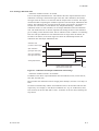
This error occurs if the detector heater temperature does not rise during warm-up, or if
the temperature falls below 7308C or exceeds 7808C after warm-up is completed. In
addition, when error-2 occurs, alarm 10 (cold junction temperature alarm) or alarm 11
(thermocouple voltage alarm) may be generated at the same time. Be sure to press the
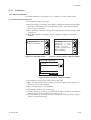
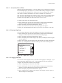
error indication to get a description of the error and confirm whether or not these alarms
are being generated simultaneously.
If Alarm 10 is generated, a failure in the cold junction system is suspected. In this case,
follow the procedure according to troubleshooting for alarm 10 in Section 12.2.2.5.
If Alarm 11 is generated, a failure in the thermocouple system located in the detector
heater is suspected. In this case, follow the procedure according to troubleshooting for
Alarm 11 in Section 12.2.2.6
If this failure occurs immediately after the power is supplied, the polarity at thermocouple input connection (TC+, TC-) on the converter may be reversed. Check the
connection from the detector.
Causes considered for cases where Error-2 occurs independently are shown below.
(1) Faulty heater in the detector (heater wire breakage)
(2) Faulty thermocouple in the detector
(3) Faulty cold junction sensor located at the detector terminal block.
(4) Failure in electrical circuits inside the converter
(5) Heater temperature control overcurrent limiting triggered.
(6) TC+ TC- thermocouple terminals wired to detector with reverse (wrong) polarity.
Overcurrent protection is triggered if there are problems in the heater wiring. When the
protective circuit is triggered, the internal fuse blows and the heater is disconnected,
resulting in Error 2 (temperature failure).
<Locating cause of failure, and countermeasures>
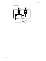
(1) Turn off power to the converter.
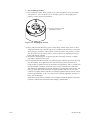
(2) Remove the cable from terminals 7 and 8 of the detector and measure the resistance
value between these terminals. The heater unit will be normal if the resistance is
lower than about 90V. If the resistance value is higher, failure of the heater unit is
suspected. In this case, replace the heater unit (refer to Section 11.1.3, “Replacement
of the Heater Unit”). In addition, check that the wiring resistance between the
converter and detector is 10V or less.
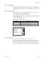
(3) Ensure that TC+ terminal (terminal 3 in detector) is connected to converter TC+
terminal, and TC- terminal (terminal 4) is connected to converter TC- terminal.
(4) Remove the wiring from terminals 3 and 4 of the detector and measure the resistance
value between these terminals. The thermocouple will be considered normal if the
resistance value is 5V or less. If the value is higher than 5V, it may indicate
thermocouple wire breakage or a state in which the thermocouple wire is about to
break. In this case, replace the heater unit (refer to Section 11.1.3, “Replacement of
the Heater Unit”). Also, check that the wiring resistance between the converter and
detector is 10V or less.
IM 11M12A01-02E
12-3