1
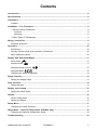
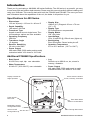
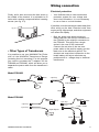
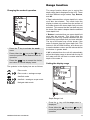
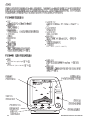
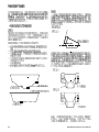
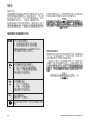
NAVMAN F440 * NAVMAN NAVMAN FISHFINDER F400/F440 ENGLISH ........................................................................... 5 CHINESE ......................................................................... 21 Contents Introduction ...................................................................................................................................... 6 Specifications .................................................................................................................................. 6 Installation ........................................................................................................................................ 7 Location ........................................................................................................................................ 7 Installation – The Transducer ......................................................................................................... 8 • Transom Mount Transducer ...................................................................................................... 8 Location ................................................................................................................................. 8 Mounting ................................................................................................................................ 8 • Other Types of Transducers ..................................................................................................... 9 Wiring connection ........................................................................................................................... 9 Electrical protection ..................................................................................................................... 9 Operation ........................................................................................................................................ 10 Introduction ................................................................................................................................ 10 Primary functions and quick operation introduction ................................................................. 10 Menu selection system ............................................................................................................. 10 Display and Operating Modes ..................................................................................................... 11 Echo mode Autofish mode ........................................................................................................................ 11 ................................................................................................................... 11 Analogue-scope function ................................................................................................. 12 Navigate Mode ........................................................................................................... 12 Changing the mode of operation ............................................................................................... 13 Range function .............................................................................................................................. 13 Setting the display range ........................................................................................................... 13 Gain function ................................................................................................................................. 14 Setting the gain .......................................................................................................................... 14 Display scroll speed ...................................................................................................................... 15 Setting the scroll speed ............................................................................................................. 15 Alarms ............................................................................................................................................. 16 Anchor Drag Alarm .................................................................................................................... 16 Setting the alarms ...................................................................................................................... 16 Setup Menu ..................................................................................................................................... 17 Changing the setup functions .................................................................................................... 17 Setup Menu – Speed & Temperature (FISH440 only) ............................................................... 18 Changing the speed & temperature setup ................................................................................ 18 Troubleshooting ............................................................................................................................ 19 NAVMAN Fishfinder User Manual F4X0/ENG/1A 5 Introduction Thank you for purchasing a NAVMAN 400 series fishfinder. The 400 series is a powerful, yet easy to use sonar fish and bottom depth detector. Please read this manual carefully before installing and using your fishfinder. This manual deals with both the FISH400 and FISH440. The more you know and understand about the capabilities of the unit, the better it will perform for you. Specifications for 400 Series Specifications • Dimensions 132 mm W(max) x 133 mm H x 46 mm D • Depth Capability 180 metres, 600 feet • Transducer Type Aquatic transom-mount single beam. Thru hull transducer options are also available. • Operating Frequency 200 KHz • Transducer Angle 15 degrees • Receiver Sensitivity 30 micro volts RMS • Power Output 400 watts RMS (3200 watts peak-to-peak) maintained within 10% down to 10.5 volts. • Display Size 100mm (4¼") Diagonal. 82 mm x 76 mm (3¼" x 3") • Display Type STN temperature compensated • Display Matrix 100 x 64 pixels • Input Voltage 10 to 18 volts DC @ 150 mA max. (lights on) • Backlighting Even illumination. Seven levels plus off. • Operation Temperature 0°C to 40°C ambient ( 32°F to 104°F ) Additional FISH440 Specifications • Boat Speed 0.0–50.0 kts, mph, kph user selectable • Water Temperature 0.0–40.0°C (32.0–99.0°F) user selectable Display is backlit for Night Operation Power On/Off Menu Exit NAVMAN • Log Records up to 9999.9 nm, km, stored in memory, resetable. • Power Output 440 watts RMS (3500 watts peak to peak) maintained within 10% down to 10.5 volts. FISH400 Active alarms indication F=Fish, D=Deep, S=Shallow Enter Menu Mode Advance to Next Menu Backlighting On/Off Change Value Down Alarms On/Off Change Value Up 6 Move Through Menu Items NAVMAN Fishfinder User Manual Installation Location The FISH400 and FISH440 are water resistant and may be mounted and operated in many positions thanks to its compact and robust bracket, associated with a swivel support. Note It may be advisable to install the transducer and wiring before finalising the location of the display head and bracket. When installing the display head, select a position where it will be: • at least 300 mm ( 12" ) away from the compass. • at least 300 mm ( 12" ) away from any radio transmitter, such as the VHF. • easy to read by the helmsman and crew while under way. • protected from physical damage during rough sea passages. • have easy access to the 12 volt power source. • convenient to route the transducer cables. 35.0 (1.4") 132.0 (5.2") FISH400 149.0 (5.9") 133.0 (5.2") NAVMAN 81.5 (3.2") NAVMAN Fishfinder User Manual 7 Installation The Transducer Read this section carefully before attempting the transducer installation. Remember, the transducer location is the most critical part of the installation. If this is not done properly, the transducer can’t perform at its designed potential. Therefore the performance of the fishfinder, especially at higher speeds, will not be satisfactory. • Transom Mount Transducer Mounting Once the best location of the transducer is determined, hold the transducer and bracket against the transom. The bottom surface of the transducer needs to sit parallel to the surface of the water for the best signal return. The lower face of the transducer should extend down below the bottom of the hull so that it will be below the surface of the water at high speeds. (See fig. 2.1) Location The transducer can be installed on any outboard or sterndrive powered boat. The transom mount transducer has a safety “kick up” mounting bracket to help minimise damage to the transducer should it impact the bottom or floating debris in the water. fig. 2.1 Minimum immersion required Select a position for the transducer that will: • • • • • • allow the transducer a smooth flow of water over its surface at all times. ensure a mount as deep in the water as possible. be clear of any interference from the trailer when launching or retrieving the boat. be away from planing strakes or other projections from the hull that may cause aerated water to flow over the face of the transducer. be away from the propeller be at least 150 mm ( 6" ) away from the keel of the boat. Mark the transom through the bracket slots to correctly place the two outer screws. Now drill the two holes in the centre of the slots. This will allow you to adjust the transducer position later on if required. Use two of the three stainless screws supplied to attach the bracket to the transom. Ensure the lower face of the transducer is parallel with the ground (see fig. 3.1 and 3.2). Tighten the two screws. fig. 3.1 DEEP-“VEE” HULL Poor Location Poor Angle Good Location and Angle fig. 3.2 FLAT-BOTTOM HULL Good Location 8 NAVMAN Fishfinder User Manual Wiring connection Electrical protection Finally, drill a hole and insert the third screw in the middle of the bracket. It is advisable to fill holes with a sealing compound before inserting screws (see fig. 3.3). • Your fishfinder has an internal electrical protection system for over voltage and short circuit situations. It is not necessary to use a fuse or a circuit breaker. If possible, route the transducer cable away from other wiring on the boat. Electrical noise from engine wiring, bilge pumps, and other equipment can affect the display. fig. 3.3 • • Other Types of Transducers It is possible to use your NAVMAN Fish Finder with all the NAVMAN Transducers Range (including thru-hull mounting). For this purpose you need to purchase the Y adaptors for the FISH400 and FISH440, which will allow you to separate the power cable from the transducer’s cable. Both the power and depth transducer cables lead into one four pin connector on the FISH400 or the eight pin connector on the FISH440. This plugs into a single socket in the rear of the instrument. Connect the red wire of the two-core power cable to the positive supply and the black wire to the electrical ground. The shortest and most direct connection to the boat’s battery will help to eliminate any problems due to voltage drop or electrical interference. Model FISH400 Red Black 4 pin Fuji Red 4 pin Fuji Depth Black F400 Adaptor Cable Depth Model FISH440 Red Black 2 pin Fuji Red 2 pin Fuji 8 pin Fuji 8 pin Fuji Black F440 Y-Cable Depth/Speed Depth NAVMAN Fishfinder User Manual Speed 9 Operation Introduction The FISH400 and FISH440 use sonar technology to display lake or seabed contours and to detect fish. The system consists of an LCD display unit and a depth transducer positioned in the water. The model FISH440 is also supplied with integrated boat speed and water temperature sensors. Primary functions and quick operation introduction Turns the power ON and OFF • • Press for one second to turn the power ON Press and hold for three seconds to turn the power OFF Selects digital information to be displayed in the top left corner of the Fish Finder screen. Returns the unit to operating mode from any menu. Turns the backlighting ON or OFF • • Press once to turn the backlights ON Press again to turn the backlights OFF Decreases setting values in menus. Turns the alarms ON or OFF • • ∗ Press once to turn the alarm ON Press again to turn the alarm OFF The LCD screen is menu driven for ease of use. The automatic detection can locate and display the position of fish with three different size fish symbols. This feature can be disabled so that the LCD will display only the raw electronic signals. Experienced users can use this mode to extract even more information about the water and seabed conditions. Note Momentarily pressing the key removes or displays depth, speed and temperature data (depth only in the FISH400) from the upper left corner of the display. The format chosen is retained in memory when the power is switched off. Menu selection system Your fishfinder has many features that may be selected for adjustment. Each of these features have a menu screen. You may access all the menu screens by repeatedly pressing the key. ∗ Menus such as the manual gain control, shallow and deep water alarms have additional numerical control windows. The number in this window is changed by using the V and ^ keys. Any changes made are recorded in memory as soon as you exit the menu screen. All changes are stored in memory when the power is switched off. Note To exit or clear any menu from the screen, press the key. Increases setting values in menus. Enters menu mode Advances to the next menu Moves through the list of items in each menu 10 NAVMAN Fishfinder User Manual Display and Operating Modes The FISH400 has five modes of operation. These are Echo, Echo + Analogue Scope, AutoFish, AutoFish + Analogue Scope and Navigate. Autofish mode Echo mode The Autofish mode automatically analyses the return echoes and displays echoes with fish icons (the bigger the echoes, the bigger the icon!). The Echo mode displays the return signals as they are received from the transducer. Fish appear as arches and not as fish symbols. The length of the arch will indicate the relative size of the return echo and size of the fish. The Echo mode enables the unit to display echoes caused by surface turbulence, thermal layers, plankton or transducer noise when the boat is moving. This mode is very useful for the experienced user. The return echo is caused when the sonar beam strikes the air stored in the fishes swim bladder. Certain types of fish have larger swim bladders than normal so the size of the icon is not always a reliable way to indicate the relative size of the fish. In the Autofish mode, unnecessary surface noise is reduced from the top of the screen. This mode is recommended when your boat is moving along at higher speeds. The digital display in this sample window is indicating the depth of the bottom. The display units are also user selectable NAVMAN Fishfinder User Manual 11 Analogue-scope function Model FISH400 Analogue Scope Displays depth only Model FISH440 Current Echo The Analogue-scope function is available in either the Echo or Autofish modes. This feature displays an intensity graph of the current echoes down the right hand side of the screen. The information can be used to help determine the type of bottom structure and the size of fish. The strength of the echo is proportional to size or number of pixels visible in the analogue section of the screen. This feature will help to determine the strength of the return echo from the bottom and therefore how hard or soft the bottom may be. Navigate Mode In this mode the depth, speed and temperature are displayed in large easily readable digits. This is useful when navigating to your favourite fishing location. To increase precision, the values are displayed in 0.1 increments. You may display water temperature in degrees °C or °F. The depth of the bottom in feet, metres or fathoms. The speed of the boat in mph, knots or kph. The log will display the total distance in the speed unit you have selected. The log total is automatically stored in memory when the power is switched off or removed but this value can be reset to zero (see SETUP menu). When either or all of the Fish (F), Shallow (S) or Deep (D) alarms are active they are displayed at the top left corner of the screen. 12 NAVMAN Fishfinder User Manual Range function Changing the mode of operation The range function allows you to control the depth range that is displayed on the LCD. There are three different range modes; Top, Bottom, and All. If Top is selected then a lower depth limit value must also be selected. This mode locks the display to show only echoes from the surface of the water down to the lower depth limit you have selected. This means that the sea bed may not be shown if the water is deeper than the selected lower depth limit. ∗ key to activate the mode • Press the menu • Press either the key or the key to move the pointer to the desired mode of operation • Press the key to accept the choice and return to normal display mode If Bottom is selected then an upper depth limit must also be entered. This mode locks the display to show only echoes between the sea bed and the upper depth limit you have selected. The top of the water may not be shown if the water is deeper than the upper depth limit. This feature is like a ZOOM function, as it allows you to see the bottom contour and fish echoes above the bottom in greater detail. If All is selected then the unit will automatically adjust the display range to show both the top of the water and the sea bed no matter what the depth of the water is. Setting the display range The symbols in the display box are as follows Echo mode Echo mode + analogue scope Autofish mode Autofish + analogue scope mode Navigate data mode Depth Range Limit NAVMAN Fishfinder User Manual ∗ • Press the displayed. key until the range menu is • Press either the key or the key to move the pointer to the desired mode of operation 13 • If the desired mode is Top or Bottom then use the V or the ^ key to adjust the limit value to the desired level • key to accept the choice Press the and return to normal display Setting the gain Gain function The gain is a measure of ability to receive weak signals. The higher the gain setting, the better the unit is able to pick up weak return signals. Deep water operation requires the gain to be set to a higher value due to loss of signal in the water. There are two gain modes that can be selected, Manual and Auto. If Manual is selected then a gain setting from 0 to 15 must also be entered. This will be the value of gain that is always used when displaying information on the screen. A low gain number may be suitable in shallow water but will need to be increased for deep water operation If Auto is selected then the gain will automatically vary as the water depth changes. This feature is particularly useful if you are fishing areas where the depth changes suddenly. In Auto mode, you can set the auto-gain value to provide a consistent image of the bottom, regardless of the bottom type. A low auto-gain setting will cause a thin bottom image to be displayed. A high autogain setting will result in a thick bottom image. This adjustment is particularly useful with a weak return signal from a muddy or silty bottom. Normally, in these conditions the auto-gain will increase the gain to a level that may make the display appear too cluttered, making it difficult to distinguish fish. In this situation the auto-gain can be reduced to display a weak bottom image but with improved fish images. 14 ∗ • Press the displayed • Press either the key or the key to move the pointer to the desired mode of operation If the desired mode is Manual then use the V or the ^ key to adjust the value to the desired level • • • key until the gain menu is Press the key to accept the choice and return to normal display mode If the desired mode is Auto then use the V or the ^ key to adjust the value to the desired level. In Auto mode the gain will be controlled to show the same bottom detail irregardless of depth NAVMAN Fishfinder User Manual Display scroll speed The scroll speed is the speed that the picture moves across the screen. It is adjustable in three distinct steps, slow, medium and fast. In general the faster scroll speed will work better with higher boat speeds. The slower scroll speeds are more suitable for slow speed trolling and slower vessels. The most suitable scroll speed is determined by experimentation Setting the scroll speed ∗ key until the speed menu is • Press the displayed • Press either the key or the key to move the pointer to the desired scroll speed • Press the key to accept the choice and return to normal display mode NAVMAN Fishfinder User Manual 15 Alarms There are three different types of alarms, Fish, Shallow, and Deep. All the alarms activate the internal buzzer if their alarm condition is met. The buzzer will provide three different alarm signals. A short alarm signal for a mid water echo, such as a fish, a long continuous signal for a shallow water alarm and a series of short signals for a deep alarm. Each alarm can be individually enabled or disabled. All enabled alarms can be simultaneously disabled with a single key press. Setting the alarms The alarm indicator bar on the top left of the display shows which alarms have been selected. They are fish ‘F’, shallow ‘S’, and deep ‘D’. Fish Alarm Alerts you with a single short signal when an object that could be a fish is detected. The alarm for a small fish is shorter than the alarm for a bigger fish. Shallow Alarm Alerts you when the water depth is shallower than the shallow alarm setting, i.e., the water becomes too shallow. Deep Alarm Alerts you when the water depth is deeper the deep alarm setting, i.e., the water becomes to deep. Press the displayed • Press either the key or the key to move the pointer to the required alarm Use the V or the ^ key to adjust the alarm setting to the desired depth level. OFF is shown if shallow alarm value is 0 or deep alarm value of 600 feet is selected • Alarms on the FISH440 When either or all of the Fish, Shallow or Deep alarms are active they are displayed on the screen. When an alarm is triggered there is a beep and the corresponding alarm’s figure flashes on and off. ∗ key until the alarms menu is • • Press the key to accept the choice and return to normal display mode Anchor Drag Alarm The Shallow and Deep Alarms can be set just above and below your anchored depth. An alarm will sound if your anchor drags and you drift into deeper or shallower water. Be sure to disable the fish alarms in this mode to prevent false anchor drag alarms due to fish. 16 NAVMAN Fishfinder User Manual Setup Menu The setup menu enables you to customise the ‘look and feel’ of the instrument. There are six parameters that can be adjusted. Lamp intensity, units of measure, keel offset, training mode, LCD contrast and white line operation. Changing the setup functions Lamp Intensity The intensity of the night vision lights can be adjusted from 1 to 7 and OFF. Units Of Measure Depth can be displayed in either feet (FT), meters (M), or fathoms (FA). Keel Offset The depth of water is normally measured from the face of the transducer to the bottom. You can enter an offset which will be added or subtracted from the calculated depth before it is displayed on the LCD. Entering a negative offset can be used to display the depth of water below the keel. Entering a positive offset can be used to show depth from the surface to the bottom. When entering zero as an offset, the fishfinder will display depth of water below the transducer. Training Mode This setting will enable a simulation mode which allows you to learn to use all the different features in this instrument. LCD Contrast You can adjust contrast level from 0 to 7 to match your preference. Special circuitry will also automatically adjust the contrast for changes due to temperature. ∗ • Press the displayed • Press either the key or the key to move the pointer to the required setup item Use the V or the ^ key to adjust the setting to the desired value • • key until the setup menu is Press the key to accept the choice and return to normal display mode White Line This feature displays the bottom signal as a thin line, with a variable width band beneath it. This indicates the bottom hardness and also allows you to separate targets near the bottom of the sea bed. This function will also remove most surface echo signals from the top of the screen. NAVMAN Fishfinder User Manual 17 Setup Menu Speed & Temperature (FISH440 only) Changing the speed & temperature setup The model FISH440 fishfinder is able to display boat speed, water temperature, and water depth. This menu enables you to customise the display of speed and temperature and to change the calibration setting of these features. Temperature units Temperature can be displayed in either °C or °F. Temperature calibration If the displayed temperature is known to be wrong then it can be adjusted using this function. The calibration value is saved in memory automatically. Speed units of measure Speed can be displayed in either knots (KTS) miles per hour (MPH) or kilometres per hour (KPH). Speed calibration If the displayed speed is known to be wrong then it can be adjusted using this function. The calibration value is saved in memory automatically. Reset log The distance log can be reset by changing this option from ‘NO’ to ‘YES’. If the selection is YES, the log will be reset when you exit this menu. ∗ key until the setup 2 menu is • Press the displayed • Press either the key or the key to move the pointer to the required setup item Use the V or the ^ key to adjust the setting to the desired value • • 18 Press the key to accept the choice and return to normal display mode NAVMAN Fishfinder User Manual Troubleshooting The Fishfinder won’t turn on: 1. Check the power cable socket at the back of the Fishfinder. 2. Make certain the power cable’s red wire connects to the positive battery terminal and the black wire to negative or ground. 3. Measure the voltage at the unit’s power terminals. It should be at least 10 volts. If it isn’t: • the battery terminals or wiring on the terminals are corroded • the battery needs charging. • the wiring to the unit is defective 4. Check any fuses you may have placed in the line. The Fishfinder freezes, locks up, or operates erratically: 1. Electrical noise from the boat’s engine or an accessory may be interfering with the sonar unit. To stop this, try: • re-routing the power and transducer cables away from the other electrical wiring on the boat • routing the unit’s power cable directly to the battery instead of through a fuse block or ignition switch 2. Inspect the transducer cable for damage or pinched wires. 3. Check the transducer and power connector. Make certain it is securely plugged into the unit. Weak bottom echo, digital readings erratic, or no fish signals: 1. Make certain the transducer is pointing straight down. 2. Electrical noise from the boat’s motor can interfere with the Fishfinder. This causes the Fishfinder to automatically decrease the gain level unless the gain control has been set manually. The Fishfinder thus eliminates weaker signals such as fish or even the sea bed from the display. 3. Manual gain may be set too low, if you have the instrument set in manual mode. 4. The water may be deeper than the Fishfinder’s ability to find the bottom. If it cannot find the bottom return signal while it is in the automatic mode, the display will flash continuously. It may change the range to a realistic one, and increase the sensitivity. As you move into shallower water, a bottom signal should appear. 5. Check the battery voltage. If it is too low, the unit’s transmitter power is also low, reducing its ability to find the bottom or targets. Bottom echo disappears or erratic digital reading while your boat is moving: 1. The transducer may be in turbulent water. Air bubbles in the water disrupt the Fishfinder signals, interfering with its ability to find the bottom or other targets. This often happens when you reverse the boat. The transducer must be mounted in a smooth flow of water in order for the Fishfinder to work at all boat speeds. 2. Again, electrical noise from the boat’s motor can interfere with the Fishfinder. NAVMAN Fishfinder User Manual 19 20 NAVMAN Fishfinder User Manual 22 22 23 23 24 24 24 24 25 25 25 26 26 26 26 27 27 27 28 28 29 29 29 30 30 31 31 32 32 32 33 33 34 34 35 NAVMAN Fishfinder User Manual F4X0/CHI/1A 21 0°C ~ 40°C ( 32°F ~ 104°F ) 0.0–50.0 kts, mph, kph 0.0~40.0C (32.0~99.0F) NAVMAN 22 FISH400 NAVMAN Fishfinder User Manual 35.0 (1.4") 132.0 (5.2") FISH400 149.0 (5.9") 133.0 (5.2") NAVMAN 81.5 (3.2") NAVMAN Fishfinder User Manual 23 Poor Location Poor Angle 24 Good Location and Angle NAVMAN Fishfinder User Manual fig. 3.3 Model FISH400 Model FISH440 NAVMAN Fishfinder User Manual 25 ∗ 26 NAVMAN Fishfinder User Manual NAVMAN Fishfinder User Manual 27 28 NAVMAN Fishfinder User Manual NAVMAN Fishfinder User Manual 29 0~15 30 NAVMAN Fishfinder User Manual NAVMAN Fishfinder User Manual 31 32 NAVMAN Fishfinder User Manual 0~7 NAVMAN Fishfinder User Manual 33 34 NAVMAN Fishfinder User Manual NAVMAN Fishfinder User Manual 35 36 NAVMAN Fishfinder User Manual NAVMAN Fishfinder User Manual 37 38 NAVMAN Fishfinder User Manual NAVMAN Fishfinder User Manual 39 40 NAVMAN Fishfinder User Manual NAVMAN Fishfinder User Manual 41 42 NAVMAN Fishfinder User Manual NAVMAN Fishfinder User Manual 43 44 NAVMAN Fishfinder User Manual NAVMAN Fishfinder User Manual 45 46 NAVMAN Fishfinder User Manual NAVMAN Fishfinder User Manual 47