1
Ampro Installation
Configuration and Connections
Ampro LCD-150 Projector Configuration
Verify that the System 8/10 PLUS is already configured for the Ampro LCD-150
projector. The general setup is explained on page 3-4 and the switch settings for
the projector are repeated below.
1. Use a small screwdriver to remove the access cover from the System 8/10 PLUS
front panel. See bottom of page 3-3. The label on the back of the access cover
also has the configuration information.
__________ Before changing anything, remove the AC power cord to the System 8/10 PLUS
to verify that the main power is OFF; also turn the projector power OFF.
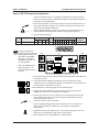
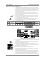
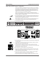
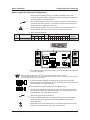
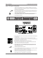
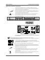
2. Set the switches as follows:
Config
Model
Rotary Switches Cable
as
RS1 RS2 RS3 RS4 J2/J3
Ampro LCD-150
0
0
0
B
J2
SW15 Settings
1 2
RS5 is for RGB switching
delay. See page 3-4 for
more information on switch
functions.
4
5
6
1
2
3
4
5
6
Comm
7 8
↓ ↓ ↑ ↓ ↑ ↓
ON
_ When connecting the
projector for Video Loopback
(VLB) operation: SW15, DIP
switch #8 must be Down.
See page 3-4 for switch
description, and page 2-10
for VLB operation.
3
9 10
↓ ↓ ↑ ↓
7
8
9
Adapter
<none>
10
SW15 DIP Switch
RS2
RS3
RS5 RS2 RS1
RS4
RS1
RS3 RS4
Configured For:
RS-232
3. Use a grease pencil (or other rub-off marker) to mark the space on the label next
to “Ampro LCD-150”.
4. Locate the switcher’s Address DIP switches on the rear panel, lower right.
Unless this is part of a master/slave system, set #3 and #5 to the up position and
the others down. See illustration to the left.
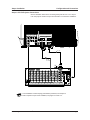
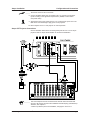
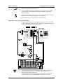
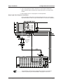
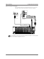
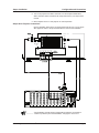
Use the illustration on the facing page to do the following steps.
5. Connect the Comm Adapter’s 15-pin male connector to the 15-pin female
“REMOTE” connector on the side panel of the projector.
6. Connect the CC-50' (or CC-100') cable from the 15-pin male connector of the
Comm Adapter to the 15-pin HD “Projector Control” port located on the rear
panel of the System 8/10 PLUS.
______ Secure the screws on all D connectors.
7. Connect the BNC (RGBS) cables from the System 8/10 P LUS outputs to the
Ampro LCD-150 projector’s “RGB1 INPUT” according to the application
requirements.
8. Apply Main Power to the System 8/10 PLUS by connecting the power cord. The
Main Power LED should light. Apply power to the projector.
9. Return System 8/10 PLUS and projector to normal operation.
Extron • System 8/10 PLUS • User’s Manual • P/N 68-404-01 Rev. A
Page 1