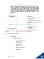
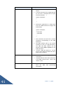
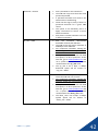
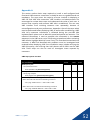
1
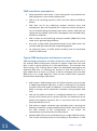
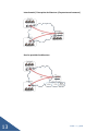
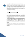
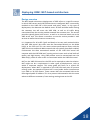
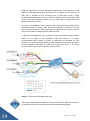
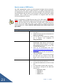
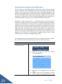
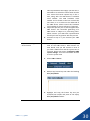
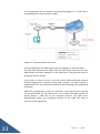
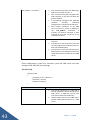
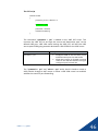
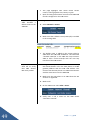
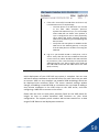
Initial setup guide ViBE V3 Contact information United Kingdom Office 8-9 Wharfside House Prentice Road Stowmarket Suffolk IP14 1RD Main switchboard: +44 (0) 1473 359810 Sales: +44 (0) 1473 359811 Website: www.voipex.co.uk Voipex information: [email protected] About this guide The goal of this guide is to introduce network administrators, support and installation personnel, to the ViBE technology as well as set guidelines for best practices when deploying the ViBE system. This ‘Initial setup Guide’ will take you through the basic configuration of a ViBE server, and show you how to configure your first ViBE tunnel. For additional information, here are some sources of knowledge on topics, which are not covered in this guide: Voipex ViBE Administrator's Guide - In-depth information on how to configure features of the ViBE system. See document “DOC 101 – ViBE Administrator Guide” Initial setup guide http://portal.vibesupport.com - Provides access to a support structure which includes a comprehensive knowledge base, as well as a community forum 2 Copyright Except where expressly stated otherwise, the ViBE Product is protected by copyright and other laws respecting proprietary rights. Unauthorized reproduction, transfer, and or use, can be a criminal, as well as a civil offense under the applicable law. Trademarks The ViBE logo is a registered trademark of Voipex Inc. in the United Kingdom and other jurisdictions. Unless otherwise provided in this document, marks identified by “®,” “™” and “SM” are registered marks, trademarks and service marks, respectively, of Voipex. All other trademarks are the property of their respective owners. Documentation information For the most current version of documentation, please visit the ViBE support portal at http://portal.ViBEsupport.com 3 Initial setup guide Index COPYRIGHT ...................................................................................................................................................... 3 VIBE TECHNOLOGY OVERVIEW ........................................................................................................................ 5 VOIP AND VIBE IN DATA NETWORKS ............................................................................................................... 9 MAIN BARRIERS WHEN DEPLOYING VOIP ...................................................................................................................... 9 VIBE FEATURES WHICH ELIMINATE, OR SIGNIFICANTLY REDUCE VOIP DEPLOYMENT BARRIERS: ................................................ 9 VIBE INSTALLATION ASSUMPTIONS:........................................................................................................................... 11 TYPICAL VIBE DEPLOYMENT ARCHITECTURE OVERVIEW: ................................................................................................ 11 Inter-branch / Enterprise Architecture (Corporate environment) ................................................................. 13 Service provider Architecture ........................................................................................................................ 13 Back to back connectivity of ViBE servers ..................................................................................................... 14 LICENSING YOUR VIBE DEVICES...................................................................................................................... 15 LICENSING OVERVIEW ............................................................................................................................................. 15 SERVICE PROVIDER LICENSING................................................................................................................................... 16 CONTENDED LICENSING........................................................................................................................................... 17 DEPLOYING VIBE: NAT-BASED ARCHITECTURE ............................................................................................... 18 DESIGN OVERVIEW ................................................................................................................................................. 18 CONFIGURING VIBE ....................................................................................................................................... 20 HOW TO ACCESS A VIBE DEVICE ............................................................................................................................... 21 CONFIGURING VIBE MANAGEMENT AND DEVICE SETTINGS............................................................................................. 22 ACTIVATING AND CONFIGURING THE VIBE SYSTEM ....................................................................................................... 29 CONFIGURING A CLIENT VIBE TUNNEL ....................................................................................................................... 31 DEPLOYING VIBE BEHIND A NAT ROUTER: PORT FORWARD METHOD (METHOD 1) ............................................................. 34 EXPLANATION OF THE VIBE SCRIPT COMMANDS .......................................................................................................... 40 FIGURE 4 – VIBE VPN CONNECTION ESTABLISHMENT CYCLE .......................................................................... 40 DEPLOYING VIBE USING UDP PIN HOLING (METHOD 2) ................................................................................................ 45 TESTING YOUR VIBE VPN ....................................................................................................................................... 47 DIAGRAM 3 - PATH THAT VOIP FOLLOWS WITHIN THE NAT BASED VIBE SOLUTION ...................................... 47 APPENDIX A ......................................................................................................................................................... 52 Initial setup guide 4 ViBE technology overview ViBE is a proprietary IP tunneling (“VPN”) technology, based on a powerful QoS (Quality of Service) and Voice over IP (VoIP) optimization engine which guarantees optimal voice quality and performance, whilst allowing for maximum data throughput on a given data link. The ViBE system does so by performing optimization on VoIP and data streams at the byte level, unlike traditional QoS methods which are performed at the packet level. Packets can contain a large amount of bytes, and performing packet-based QoS on VOIP and data streams result in a very rugged QoS, as well as underperforming network throughput. ViBE’s optimization engine has the ability to prioritize bytes within a packet, thus allowing for extremely fine control over voice and data streams. Such fine granular control allows ViBE to fully utilize a data link where data and VoIP is present for unparalleled QoS performance. ViBE has two primary benefits as an IP tunneling technology. First, the ability to shape VOIP and data streams with exact precision at the byte level (QoS), as well as “compress” or multiplex multiple VOIP streams into a single coherent VOIP payload. This is achieved by removing unnecessary transport and or IP headers from the IP packet. Please review the ViBE white paper (“DOC 102 – ViBE Technology Overview”) for more information on how ViBE works. This document can be found on the ViBE support portal http://portal.vibesupport.com and also under the downloads section of the Voipex website at www.voipex.co.uk. The primary benefits of ViBE are: Byte level QoS engine ViBE performs QoS at byte level. This gives unprecedented granular control on VoIP and data flow traffic shaping VoIP call multiplexing (“compression”) ViBE increases the amount of VoIP calls by as much as 5 times when compared to transmission networks without ViBE The secondary benefits are equally as valuable as the primary benefits. The ViBE VPN technology adds powerful redundancy and monitoring capabilities to each ViBE VPN tunnel. These functions provide the administrator (ISP or private company) the tools to offer unmatched flexibility and visibility into each ViBE VPN’s performance and uptime. 5 Initial setup guide Secondary benefits are: ViBE Link Bonding (VLB) The ViBE VPN technology has link bonding capabilities built in. This provides a superior redundancy option, as well as a means to increase WAN throughput capacity. A ViBE VPN can consist of multiple WAN links. Up to 8WAN links can be included in a ViBE VPN tunnel. See document “DOC 200 – ViBE Link Bonding (VLB)” for more information on how this feature works. The document also includes configuration examples. Redundant Array of Inexpensive Networks (RAIN) Mode Redundant Array of Inexpensive Networks (RAIN) is a feature which allows the ViBE engine to transmit duplicate copies of VOIP data packets over multiple WAN links configured with a ViBE VPN. This creates the highest order of redundancy for VOIP data streams at the application layer, ensuring almost bullet proof VOIP communications over multiple WAN links. This feature is essential in environments like the VoIP call Centres or mission critical VOIP environments where VoIP call redundancy is a key requirement. Voice quality and consistency is ultimately preserved by simultaneously transmitting copies of VOIP packets across multiple WAN links. The ViBE engine at each end of the ViBE VPN tunnel only forwards the best received VOIP packet to the either the VOIP PBX or and/or VOIP enabled phone. This means that if a VOIP packet is lost along the path to its destination, that ViBE will select the next best received VOIP packet. See document “DOC 201 – RAIN configuration” for more information on how this feature works. The document also includes configuration examples. Initial setup guide 6 High Availability ViBE appliances (PE and CPE) support the high availability (HA) protocol VRRP (Virtual Router Redundancy Protocol) to enable device redundancy at either, or both the ViBE server head end and/or ViBE satellite site(s). It is essential to setup you ViBE server in high availability as soon as possible, if it was not deployed in such a manner in the first place. HA configured on the ViBE servers will add another important layer of redundancy to your ViBE eco system by means of device redundancy. See document “DOC 202 – ViBE device high availability (HA)” for more information on how this feature works. The document also includes configuration examples. WAN link quality monitoring and reporting The ViBE system continuously monitors WAN link quality of all ViBE VPN connections through mechanism specifically incorporated in the ViBE VPN technology. This allows for monitoring of bi-directional link quality – i.e. ViBE allows the administrator to monitor both the transmitting- and receiving link quality from a single screen. Link quality can easily be observed on either the ViBE server or ViBE CPE. The ViBE web interface lists each individual ViBE VPN connection with its corresponding link quality statistics. The statistics consist of both receive (RX) and transmit (TX) packet loss, RX and TX jitter, RTT (round robin time), total active calls, RX and TX bytes, as well as how many VOIP calls have been blocked. These statistics provide exceptional insight into the quality of any given connected ViBE VPN connection, and thus, provides the administrator the tools to quickly troubleshoot any potential connection issue. All ViBE tunnel statistics are available through SNMP. Please visit the ViBE support portal for the latest SNMP MIB’s. Service providers can use the data collected from SNMP polls, to provide customers with utilization and performance graphs of their respective ViBE VPN connection(s). Service providers can use the SNMP data internally, to monitor customer links more proactively. 7 Initial setup guide ViBE integrates into MPLS networks From version 3, ViBE integrates into the MPLS environments. This allows traffic to be redistributed between ViBE VPN links and MPLS networks. It allows ISP’s to offer MPLS customers the benefit of ViBE by connecting existing MPLS networks with ViBE VPN networks. It also allows existing and new customers to deploy ViBE when needed and provides them the option to decommission MPLS network links which cannot provide the required VOIP and/or data optimization the ViBE system provides. Traditional MPLS networks lack the robust QoS engine that ViBE uses, and thus, MPLS QoS is done on a per packet bases, yielding once again a network link with rugged and underperforming link throughput. MPLS presently cannot provide any of the VOIP optimizations such as VOIP “compression”, alternatively known as VOIP multiplexing. See document “DOC 203 – MPLS integration of ViBE” for more information on how this feature works. The document also includes configuration examples. Initial setup guide 8 VoIP and ViBE in data networks VOIP and QoS data networks suffer from a variety of performance issues because of shortcomings in traditional transmission networks. Traditional transmission networks have not evolved to optimally address the issues that the modern day converge networks present. ViBE VPN technology offers a modern solution to address VoIP performance and QoS issues in current networks. Let’s have a closer look at what issues VoIP currently experience and how ViBE solves it. Main barriers when deploying VoIP ● Excessive bandwidth consumption of multiple VoIP calls ● High load on transit routers due to the large number of packets per second that multiple VoIP calls generate ● Latency and jitter which arises as the result of larger data packets using the same links as VOIP traffic ● The cost of high bandwidth WAN links, which are required to solve these issues using traditional methods ● Lack of CODEC support in devices ● There are complexities for enterprises wishing to deploy VoIP between sites, across the public Internet or non-private links ● The cost of providing backup solutions in order to avoid the WAN link or hardware, being a single point of failure, and ensuring that those links are available for use when required ● Lack of visibility of the real quality of a link in use ViBE features which eliminate, or significantly reduce VoIP deployment barriers: 9 ● Bandwidth used by VoIP calls is reduced, by as much as five times ● Jitter introduced by the use of router queues, is reduced to virtually zero ● QoS classes of data can receive as little as 0.4kbits/s ● Interactive traffic remains responsive because of the powerful ViBE QoS Initial setup guide ● There is no need to reduce the maximum transmission unit (MTU) of the WAN link ● Backup links can be switched to in less than a second, and without losing VoIP calls in progress ● ViBE appliances can be configured in high availability mode, with the configuration of the standby device being automatically kept in sync with the master for hardware redundancy ● Multiple links of different sizes can be combined to increase the total bandwidth available, and eliminate single points of WAN link failure. Alternatively they can be used in a redundant mode, which reduces or eliminates packet loss and makes the effect of a failed link totally invisible ● Sites can be privately linked across the public Internet. ISPs can create groups of customer sites, which form VPNs. ViBE can be integrated in the MPLS network to further extend ViBE’s optimisation into the network ● ViBE devices can be deployed in scenarios where fixed IP addressing is not available, or behind existing NAT routers ● Real time statistics are available, which indicate the quality of a WAN link in terms of latency, jitter and packet loss. These statistics are available via SNMP for alerting and historical graphing. This allows VoIP providers to be proactive in fixing WAN or VoIP related issues ● RAIN (Redundant Array of Inexpensive networks) is a feature which offers ultimate VoIP call redundancy by transmitting copied of VoIP packets simultaneously across multiple WAN links Certain criteria must be met for optimal ViBE VPN performance. As with any transmission network, packet loss and high latency will create performance issues with VoIP and/or data streams, whether or not you use ViBE. Initial setup guide 10 ViBE installation assumptions: ● Setup procedures and scripts in this setup guide, are performed on ViBE equipment in their factory default state ● ViBE is an IP tunnelling protocol (“VPN”) and uses UDP port 65500 by default ● ViBE does not fix any underlying network transport errors and subsequently, does not fix packet loss. Packet loss means that data is lost or discarded along the network path that it travels. ViBE does not regenerate lost packets, and further investigation into the WAN link(s) should be conducted ● ViBE is reliant on the underlying transport network (WAN links) to be stable and in good working condition ● Any VoIP, or data traffic transmitted outside of the ViBE tunnel, will not have ViBE QoS and ViBE VoIP multiplexing applied. ● For optimum results, all traffic (VoIP and data) must be transmitted inside the ViBE tunnel Typical ViBE deployment architecture overview: ViBE technology incorporates a number of features, which reduce the cost of the network WAN infrastructure required to support wide area voice and QoS, as well as giving visibility of its VPN performance. This translates into direct savings, such as being able to reduce the bandwidth requirements on expensive data links, or increasing the amount of VoIP calls possible on a given WAN link by as much as 5 times, as well as converging voice and data WAN links in to a single WAN link. There are also several other important benefits when deploying a ViBE system: 11 ● ViBE creates a VPN between sites; this allows customers to use private IP addressing between ViBE sites, as well as allowing ISP’s to provide the ViBE tunnel with public IP addresses. A private network similar to MPLS in concept, can be created for customers running multiple ViBE sites ● ViBE has the ability to switch to a configured backup link, in under a second, which means that if a primary link fails, the switchover to the backup link happens extremely fast, so any active VoIP calls would barely be affected, if at all ● ViBE devices support hardware high availability (HA), removing the downtime caused by a single hardware device failure, which will cause the ViBE network to fail. Configurations on the master are automatically synchronised with the slave device. ● Multiple WAN links can be combined to form a single ViBE VPN tunnel. This is more commonly known as link bonding in the industry. In ViBE Initial setup guide context, this feature is named VLB, ViBE Link Bonding. The result of a VLB ViBE tunnel, is increased bandwidth and most importantly, increased ViBE tunnel resiliency. Unlike competing technologies, ViBE can tolerate all but one link failure in a group of VLB enabled links without connectivity being lost. Another important factor is that all participating WAN links can be of different link speeds. This means that customers have the option of replacing expensive WAN links with multiple cheaper WAN links. In addition, ViBE offers the option of activating RAIN mode on VLB ViBE tunnels. RAIN mode activates ultimate redundancy for VoIP calls by transmitting copies of VoIP packets across all WAN links participating in the ViBE VLB tunnel. No VoIP packet will be lost in the event of a WAN link failure, thus ensuring the utmost uptime and redundancy for VoIP calls ● Real time and accurate WAN link statistics are available for each ViBE WAN link enabled with ViBE. Statistics include latency, jitter, packet loss and many more variables. Unlike all other such systems, these statistics are not affected by traffic on the network itself, but rather show the underlying quality of the link in question. This means that again, unlike traditional monitoring systems, latencies will not appear to increase simply because the WAN is being used to its full capacity. Packet loss and jitter figures are also available for both directions of the link independently, making diagnosis of any problems much simpler. A typical ViBE network topology can be described as hub and spoke. The head end ViBE server acts as a “VPN” concentrator. All client or satellite ViBE sites terminate their ViBE VPN tunnels on the head end ViBE server. ViBE can be deployed as a fully working VPN solution for ISP’s wishing to offer their customers the benefits of a next generation “WAN” technology, or as a closed solution in a corporate environment, as a solution to link company branch sites with headquarters. ViBE version 3 also allows for back to back connectivity of ViBE servers. This is especially useful when linking a closed corporate ViBE solution to that of a ViBE enabled ISP. The customer has full control over their own corporate ViBE system while the ISP controls their link to the customer. Initial setup guide 12 Inter-branch / Enterprise Architecture (Corporate environment) Service provider Architecture 13 Initial setup guide Back to back connectivity of ViBE servers Initial setup guide 14 Licensing your ViBE devices Licensing overview ViBE technology is licensed based. ViBE devices require an appropriate license to be loaded on the device, before it can be activated. A ViBE VPN tunnel cannot be established without the appropriate licenses loaded on both the ViBE server, as well as the ViBE CPE device. Different license types are required for ViBE servers and ViBE CPE devices. Each license is generated specifically for a given ViBE device (server or CPE), and the license is unique to that particular device. A license cannot be loaded on another device. A new license, of the same type and license parameters, must be generated and loaded on the replacement device. ViBE server licenses are renewed on a quarterly or yearly basis, depending on the selected renewal cycle. ViBE CPE licenses do not require renewal. Certain devices do require a once-off purchase of an activation license for the device. A case example would be that of the Mikrotik RB750. Providers and end users who upgrade the firmware in-house would have to purchase a once-off activation license prior to using it. ViBE server licenses are time-based. Please ensure that the date and time on your ViBE server is correct at all times. Make use of the NTP function on the ViBE server, which allows you to synchronize the device system clock to that of public internet time servers. ViBE servers have one of two license types which can be loaded. These are: IS THIS RIGHT? Service provider licenses Contended licenses Only one of these two licenses types can be loaded on the ViBE server. The service provider license is best suited for VoIP providers with a high volume of active and provisioned VoIP channels. ViBE licenses only license the VoIP multiplexing (“compression”) engine. There are no licenses required for the ViBE QoS engine, nor for the failover, link bonding or RAIN mode functions. 15 Initial setup guide A ViBE license consists of two main parameters. The first being, how many channels you can provision ViBE VPN tunnels with (“Max Calls”), and the second, how many active channels you require at any given point on your ViBE server. Based on these principles, two unique license types are available. Figure 1 - Screen snapshot of a ViBE server’s license page in the Web interface Service provider licensing Service provider licenses are based on the total number of active VoIP channels (“Max RTP”) required on a ViBE server. There is no restriction on how many VoIP channels you can provision (“Max Calls”). This type of license does cost considerably more than that of the Contended license type. This is due to the fact that an unlimited amount of channels can be allocated to a ViBE VPN tunnel. Only the current total active VoIP channels are taken into consideration. Initial setup guide 16 The following, is an example of where this type of license is applicable. A VoIP provider has 300 ViBE VPN customers. The provider allocated 10 VoIP channels to each ViBE customer. This adds up to 3000 provisioned VoIP channels (“Max Calls parameter of the license”) which is required on the ViBE server, of which only a certain percentage are active VoIP channels (“Max RTP parameter of the license”).The ViBE server is running100 active VoIP channels (RTP). At this point it would be financially viable to consider licensing only the maximum active RTP channels. The service provider license sets the Max Calls to unlimited (unlimited provisioning of channels), and sets the Max RTP to the purchased amount of RTP channels. Service provider licenses are purchased in multiples of 100 VS-100-O Server licences in multiples of 100 Contended licensing If a service provider (or entity operating the ViBE server) has more than 3000 licenses they may qualify for service provider licensing. A ViBE device is considered to be operating in “Contended Mode” whenever the total number of allocated/provisioned channel licenses exceeds the stated concurrent call handling capability of the device. The focus of contended licenses is on the maximum VoIP channels which can be provisioned (“Max calls” parameter) to ViBE CPE VPN tunnels. For example, if a 100 contended licenses are loaded on a ViBE server, you can only allocate 100 VoIP channels to ViBE CPE VPN tunnels in total. At this point, no more VoIP channels can be allocated to new ViBE sites. You would have to purchase another block of contended licenses to allocate more channels Service provider licenses work differently to that of contended licenses, by licensing the total active VoIP calls, and not the amount of VoIP channels you can allocate. Kindly refer to the section “Service provider licensing” for more information. 17 Initial setup guide Deploying ViBE: NAT-based architecture Design overview The NAT-based architecture deployment of ViBE refers to a specific manner in which ViBE servers and ViBE CPE devices are configured. NAT is essentially enabled on the ViBE CPE’s VPN tunnel end point, which, in this type of deployment, also becomes the default route. All VoIP and data traffic leaving the customer site will enter the ViBE VPN, as well as all traffic being transmitted from the service provider towards the customer site. The service provider typically hosts VoIP servers, as well as an Internet break out at the ViBE server end. This allows a customer to use the service provider’s VoIP services as well as have Internet connectivity. It is important for all traffic (VoIP and data) to be sent and received within the ViBE VPN tunnel. No traffic must be transmitted directly on the WAN link(s) at the CPE end. This can cause serious performance issues with the ViBE VPN since traditional WAN networks do not typically have QoS enabled. Furthermore the data transmitted outside of the ViBE VPN tunnel will compete with the ViBE VPN itself, causing various issues such as bad VoIP call quality and high latency. Only ViBE packets must be transmitted over the WAN link(s), while all other traffic is transmitted within the ViBE VPN tunnel. NAT on the ViBE VPN tunnel at the CPE-end is required to scale the solution. NAT might not be a requirement in other types of deployments, such as within a corporate campus. This setup guide will focus on a typical ISP deployment, where NAT is required on the ViBE VPN end point to prevent routing issues. An example of where NAT is used under these circumstances is on ADSL or 3G CPE routers. These routers NAT the connected LAN to the ISP assigned public IP address. This is to prevent LAN networks with the same subnet at different customers, from causing routing issues at the ISP. Initial setup guide 18 Diagram 1 illustrates a typical NAT based deployment. Each customer’s LAN subnet is 192.168.1.0/24. Each customer has a number of VoIP phones. A ViBE CPE is installed at the customer site. A ViBE VPN tunnel is then established between the customer’s ViBE CPE and the service provider’s ViBE server, using the customer’s WAN link. The ViBE VPN is configured as the default route for all traffic. As seen in the diagram, each customer uses exactly the same LAN subnet (192.168.1.0/24). A routing issue would be created if customer A’s VoIP phone and customer B’s VoIP phone tried to register at the service provider end, and NAT was not applied at the ViBE CPE end. To prevent a routing issue, NAT is applied. An ISP will need to review and plan which IP’s to assign to the customers ViBE VPN tunnels. It is highly recommended that a block of public IP addresses be allocated for this purpose, if a service provider wants to offer customers both VoIP, and data. Private addresses allocated to ViBE VPN tunnels will work, if a service providers plans to only offer customer VoIP services. Diagram 1 - Basic NAT-based ViBE deployment Selecting an appropriate IP address scheme to allocate to ViBE VPN tunnels is an important part of the pre-implementation and designing phase. 19 Initial setup guide Configuring ViBE A very basic configuration of the VIBE device follows. This guide does not cover advanced topics such as VLB (ViBE link bonding), link failover, or high availability (HA). You are encouraged to visit the support portal and study configuration guides on these, and many more other topics such as port forwarding and policy based routing. Details about the support portal can be found in the “About this guide” section of this document. In this section the following topics are covered: How to access a ViBE device Configuring management and device settings: o System parameters (host name) o Time and time zone o NTP o Admin password o Interface configuration o Route configuration Activating and configuring the ViBE system components: o Loading a ViBE license o Configuring a client ViBE tunnel (2 methods) ViBE CPE device behind a NAT router Deploying ViBE using UDP pin holing Initial setup guide 20 How to access a ViBE device The ViBE configuration system can be accessed through various protocols. These are HTTP, SSH, serial or SOAP interface. It is highly recommended that all configurations be done within the web interface. Only advanced users should configure ViBE via SSH or serial interface. ViBE also comes with a SOAP interface. This is ideal for service providers to integrate ViBE into their existing management systems. DHCP is configured on ETH0 (Ethernet port 0) for ViBE models XXXXX-Verify model numbers 203/503/601 and ETH1 (Ethernet port 1) for Mikrotik RB750 devices. No other ports on the ViBE devices will offer DHCP. Please ensure to connect the correct ViBE device port to your switch or computer during the initial configuration. Only a Mikrotik RB750 flashed with ViBE firmware will offer DHCP. Accessing the a ViBE device (methods) Web interface (HTTP) SSH access Serial access 21 The default LAN IP address of ViBE is 192.168.1.1 Default web GUI username and password is admin and password The web GUI can be accessed by opening up a browser and navigating to http://192.168.1.1 By default SSH is only allowed on ETH0 for 203/503/601 ViBE devices and ETH1 for ViBE enabled Mikrotik RB750’s. A suitable SSH application such as Putty can be used to access the ViBE device. Putty can be downloaded from here: http://www.chiark.greenend.org.uk/~sgtat ham/putty/ The default SSH username and password is root and password You might receive a SSH warning message the first time you connect to the ViBE device. This is normal and you can click “Ok” Only certain ViBE models have a serial port. These include 203,503 and 601 The Mikrotik RB750 does not have a serial port A standard NULL modem cable is required The COM port settings for the ViBE serial interface are o BAUD rate: 38400 o DATA bits: 8 o STOP bits: 1 o PARITY: none Initial setup guide Configuring ViBE management and device settings At this point it is assumed that your computer, and ViBE device are connected to either a switch, or your computer is directly connected to the ViBE device. Ensure that your computer’s LAN interface is configured for DHCP. You should have received a DHCP IP from the ViBE device in the 192.168.1.0/24 network subnet. If this is not the case, please check that the correct Ethernet port on your ViBE device is connected to either the switch, or computer LAN port. You can also configure your computer with a static (manual) IP address to check if you can access the ViBE device. Choose any IP between 192.168.1.100 – 192.168.1.150 for your computer. The subnet mask is 255.255.255.0. A series of system parameters will be configured first, before configuring the ViBE system- and related settings. It is crucial to change your system password during this phase for security reasons. Consider creating individual administrator accounts for each person who will be administrating the ViBE system. See document “DOC 204 – Configuring multiple administrator accounts” for more information on how this feature works. The document also includes configuration examples. Remember to click “Save Changes” to save any changes made on the current page. Your configuration on the current page will be lost when navigating to another configuration page without saving. The “Save Changes” button can be found on the bottom right-hand corner of the ViBE web interface. Multiple changes on different pages can be made without the having to “Apply Changes”. This allows an administrator to perform multiple setting changes and only commit once all the changes are done. An administrator can also “Review changes” or “Clear Changes”. “Clear Changes” allows the administrator to clear any new changes since the last “Apply Changes” Initial setup guide 22 Configuring ViBE system settings Step 1 – Access the ViBE web interface Step 2 – Change current system time, system hostname and time zone Open a web browser and navigate to http://192.168.1.1 Default web GUI username and password is admin and password 1. Select System > Setting 2. Change the current time and click SET 3. Change the time zone accordingly 4. Change the hostname to something more descriptive 5. Click “Save Changes” Step 3 – Change system password 1. Select System > Password 2. Fill in the new password and confirm 3. Click “Save Changes” Step 4 – Apply new system settings 23 1. At this point apply the current system settings by clicking “Apply Changes” Initial setup guide The next section focuses on configuring a basic interface on the ViBE device and reviewing the current routing table. Each ViBE deployment is unique. You will also learn how to add a static route. All interfaces on the ViBE device can be configured, by following these steps. The network administrator will need to configure the interface(s) with the required IP address or multiple IP addresses per interface if required, the subnet mask and optionally, a gateway address. It is also recommended to configure a DNS or multiple DNS servers to allow the NTP client to update the system time regularly. Ethernet 1 (ETH1) on a ViBE SPS-503 and SPS-601 server device will be configured with the IP addressing. Ethernet 0 (ETH) will be used as a management port. Configuring an interface Step 1 – Gather the required IP address and routing information Step 2 – Configure ETH1 interface IP address or IP addresses. Typically this will be a public IP address. ViBE CPE devices will connect to this IP address to establish a ViBE VPN tunnel. Plan ahead by selecting 2 or 3 public IP addresses which, you can load on the interface. VLB (ViBE Link Bonding) requires multiple IP addresses on the ViBE server to work. Multiple interfaces can also be used if multiple IP addresses on the same interface is not possible Netmask Default gateway DNS server address (primary and secondary) 1. Select Network > Interfaces 2. Click EDIT for the network WAN 3. On the network configuration page, complete the IP address, Netmask and gateway address Initial setup guide 24 4. Click “Save Changes” 5. Multiple IP addresses can be added on this page. Fill in another IP address in the “Alias address/cidr” textbox. The IP address must be in the format IPADDRESS/SUBNET. An example would be 202.12.1.3/29 6. Click “Save Changes” 7. Repeat steps 5 and 6 until all alias IP addresses are loaded 8. Next, fill in a DNS server in the “wan DNS Servers” textbox 9. Click ADD 10. Repeat steps 8 and 9 until all DNS servers are added 11. Click “Save Changes” 12. At this point the interface is configured with all the necessary information. Click “Apply Changes” to commit the changes Step 3 – Verify routing information 1. Select Network > Routes 2. You can view current system IP routes, as well as add a new static route. Verify that your default route is added to the routing table from the interface configuration 25 Initial setup guide Step 4 – Add a static route (optional) 1. Select Network > Routes 2. Fill in the route particulars in the static route textboxes Destination: This is the destination network Gateway: Next hop address to get to the destination address Netmask: Netmask for the destination network Metric: This is the routing administrative distance for this particular network. A lower value equals higher priority. If you are unsure, use 10 as the value Use With: Select the interface through which the traffic must be routed out (egress) Name: Give the static route a descriptive name. Example would be “voip_server”. Only use numerals, alphabetical letters and underscore _ in the name 3. Click ADD 4. Repeat steps 2 and 3 until all static routes are added 5. Click “Apply Changes” to commit the static route changes Step 5 – Connect Ethernet 1 to the Internet You can now connect Ethernet port 1 to the Internet ViBE will accept web GUI and SSH connections on Ethernet port 1. Ensure that your system password is changed prior to connecting the interface to the Internet. Initial setup guide 26 Notes: To change the LAN IP, follow the same process as changing the WAN interface. Remember that a second default gateway cannot be loaded, since it’s already loaded on the WAN interface. Leave the “Gateway” empty when configuring the LAN interface The use of the ViBE firewalling feature is subjective and unique to different architecture. A network administrator needs to decide whether to enable, or disable the ViBE firewall. By default the firewall is disabled to eliminate possible connectivity problems during the initial configuration. Always add firewalling after confirming that the ViBE system is operational and that ViBE CPE’s can successfully connect to the ViBE server The ViBE CPE WAN interface is configured in a similar fashion. Please do not fill in a gateway address for the ViBE WAN interface. This will create connectivity issues with the ViBE VPN tunnel. This only happens if the ViBE VPN tunnel on the ViBE CPE is configured as the default route. A static route towards the ViBE server will be added instead of specifying a default gateway. Configuring a static route on the ViBE CPE Step 1 – Add a static route for the ViBE server Normally a ViBE CPE will be connected to a WAN router via Ethernet port 2 The ViBE CPE’s Ethernet port 1 will be connected to a LAN switch Configure the WAN port on the ViBE CPE with an IP address and netmask. Do not fill in a gateway address 1. On the ViBE CPE select Network > Routes 2. Under the Static Routes heading fill in the required details 27 Initial setup guide Destination: This is the ViBE server WAN IP Gateway: Fill in the CPE WAN router through which the ViBE server IP can be accessed Netmask: For a single IP use the netmask of 255.255.255.255 Metric: This is the administrative distance value for routes. If unsure use 10 Use with: Select the interface that is connected to the CPE WAN router Name: Fill in a descriptive name for this route. An example would be “vibe_server” 3. Click Add 4. Next click “Apply Changes” Initial setup guide 28 Activating and configuring the ViBE system The first step is to load and activate a ViBE server license. Please read the section “Licensing your ViBE devices” for more information on which ViBE license to buy. It is safe to say that 99% of first-time ViBE deployments will require a contended license. This type of license is bought multiples of 100. The first time ViBE installer would normally load a single license of 100 VoIP channels on a ViBE server. This can easily be upgraded to more channels, as and when needed, creating a “pay as you grow” license environment. Obtaining a ViBE server license is a two-step process. Each ViBE server contains a “system serial key”, also known as a “license request key” which is unique to the ViBE device. This key must be copied and submitted to Voipex. Voipex will use this license request key to generate a ViBE license for your device. No two serial keys are the same, and it is important to note that a ViBE license key is generated for a specific ViBE device. This means that a ViBE license key can only be loaded on the device it was intended for. The process of copying and submitting the license request key to Voipex must be repeated in the event of a ViBE device hardware failure and in some instances where a firmware downgrade takes place. The followings steps will demonstrate where to obtain the license request key, as well as how to load a license key, once received from Voipex. Copying the ViBE license request key and loading the received ViBE license Step 1 – Copy the ViBE license request key 1. Select ViBE > License 2. Select all of the text under the heading “License request key” 3. Right click on the highlighted text and select “Copy” 4. Create a new e-mail, and address it to the correct person for processing. Your Voipex 29 Initial setup guide sales representative will supply you with the email address to which this information must be sent. Paste the license request key in the email, along with the ViBE device’s hardware serial number. The ViBE hardware serial number can be found on the box in which the unit came, or on a sticker on the underside of the ViBE device. Please record this hardware serial number for future reference if required. 5. Voipex will process your e-mail and generate a ViBE license. The successful generating of a ViBE license is subject to a purchasing order. Please contact your ViBE sales representative should you have any queries with this process 6. Proceed to step 2 if you received your ViBE license Step 2 – Loading a ViBE server license 1. It is very important to have the correct system time on the ViBE server’s. Vibe licenses are time bound, and you will receive an error if you load a ViBE license and the system time is incorrect. Please see section “Configuring ViBE system settings” for more information on how to set the system time 2. Select ViBE > License 3. Remove any license key text under the heading File: /etc/vibe.lic 4. Highlight and copy the license key text you received from Voipex and paste in the empty File: /etc/vibe.lic textbox Initial setup guide 30 5. Click “Save Changes” 6. Click “Apply Changes” to load and apply the ViBE license If you receive an error when applying the ViBE license Please consult Voipex if you receive a license load error and your system time is correct System time can be verified by going to the System > Setting page The system time is shown in the “Time settings” section Configuring a client ViBE tunnel At this point your ViBE server is configured with the necessary interface and routing configurations, connected to the Internet, as well as being accessible by the public. Your ViBE CPE can be configured, using the same steps outlined for the ViBE server. It is essential that you are able to ping your ViBE server’s WAN IP, as well as being able to access your ViBE server’s web interface from the Internet. Please verify this connectivity from a computer, or laptop which is not connected to the same WAN connection as your ViBE server, but which is connected to the Internet, via a different WAN connection such as 3G. This will verify that public connectivity to your ViBE server is possible, even from a different WAN connection. 31 Initial setup guide It is equally important to ensure that the ViBE CPE has Internet connectivity, and that the ViBE CPE can ping the ViBE server’s WAN IP. Basic end to end IP connectivity is required to ensure that a ViBE VPN establishes successfully. The same holds for any VPN protocol such as L2TP or PPTP. The ViBE CPE must be able to communicate with the ViBE server to establish a ViBE VPN. Where possible, it is best practice to always use public IP addresses on the ViBE server, and avoid using private IP addresses on the WAN facing interface. Please ensure that the correct ViBE port is forwarded to the ViBE server in cases where the ViBE server is installed behind a router performing NAT. ViBE CPE’s are almost always installed behind a WAN router performing NAT at the customer site. As mentioned, ensure that the correct ViBE port is forwarded to the ViBE CPE interface - i.e. port forward the ViBE port to the ViBE CPE. The default ViBE port is UDP 65500. Each ViBE device is rated to handle a set maximum number of concurrent VoIP calls. Ensure that you select the correct model on both the ViBE server and CPE end points. ViBE server devices SPS-503 SPS-601 Maximum concurrent VoIP call capacity 150 3000 ViBE CPE devices ViBE Mikrotik RB750 P2PB-203 Maximum concurrent VoIP call capacity 30 200 Note: Maximum concurrent VoIP call capacity will be affected by a number of processing factors such as excessive data, RAIN mode, Bonding and number of remotes connected to the server devices. Capacity planning is essential, as well as monitoring ViBE and system resources, to ensure optimal performance. Initial setup guide 32 The configuration will be based on the following diagram 2. A ViBE CPE is installed behind a router performing NAT. Diagram 2 – ViBE CPE behind a NAT router In this configuration the ViBE logical network topology is a hub and spoke. The ViBE CPE represents the spoke and the ViBE server serves as the hub. ViBE tunnels are called “Remotes” in the ViBE scripts. This guide will assist in setting up the first remote. A key factor to keep in mind is that the actual ViBE tunnel and protocol related configuration is done by using ViBE scripting. The ViBE scripting is independent from any network and network related settings like routing and firewalling. ViBE Client configuration is kept to a minimum. The majority of the settings can be provisioned via the ViBE server. This enables the ViBE installer to quickly deploy a ViBE CPE at the customer premise. The ViBE server automatically pushes the configured settings to the ViBE CPE when it connects to the ViBE server. 33 Initial setup guide There are two methods to configure the ViBE CPE in order to allow a ViBE tunnel to establish. Both options are described as configured in the subsequent sections. In principle, the two ViBE CPE deployment options are: 1) Port forward the ViBE VPN port to the ViBE CPE (UDP 65500) 2) UDP pinhole technique (no port forwarding required) Each deployment method uses a slightly different ViBE script. The changes will be highlighted and discussed in the setup steps. Deploying ViBE behind a NAT router: port forward method (method 1) Please consult the user manual of the router being used at the customer site, in order to configure the required port forwarding rule. This guide does not cover those procedures. It is very important to ensure that port forwarding is done correctly. Failure to forward the required ViBE port to the ViBE CPE will cause the VPN not to establish. UPD port 65500 must be forwarded to the ViBE CPE. Firstly, connectivity to the Internet from the ViBE CPE will be performed, before proceeding to configure the ViBE scripts on both the CPE and server. Configuration will start at the ViBE server Setup a ViBE tunnel Step 1 – Setup the ViBE server script The ViBE server requires a “remote {…}” statement for each ViBE CPE tunnel The ViBE server uniquely identifies incoming ViBE CPE tunnel packets by using the MAC address of the ViBE CPE device. The MAC address of any ViBE device can be found on the Info > System page of the web interface Before continuing, collect the ViBE CPE device MAC address 1. Select Vibe > Configuration Initial setup guide 34 2. There will be an example configuration in the ViBE configuration textbox You can delete all of the text in the textbox. A new ViBE configuration script will be generated in its place, in the next steps 3. Type the following into the ViBE script textbox remote AA:BB:CC:DD:EE:FF { name = “Customer A tunnel” provision = yes password = test123 up_rate = 3500 down_rate = 350 inet_address = 172.16.1.1 max_calls = 10 } 35 Initial setup guide Your ViBE server script textbox will look as follows: 4. Click “Save Changes” 5. Next click “Apply changes”. This will enable the ViBE VPN tunnel Step 2 – ViBE CPE: Perform basic Internet connectivity test Repeat steps 3 to 4 for each ViBE CPE tunnel you want to add. All ViBE server related configuration and ViBE CPE VPN configuration is done in this area. Remember to replace AA:BB:CC:DD:EE:FF with the ViBE CPE’s MAC address obtained in earlier steps An explanation of each configuration step will be discussed at the end of these instructions At this point the ViBE server is fully configured and ready to establish a ViBE tunnel with the ViBE CPE. The ViBE server will only establish a VPN with the ViBE CPE device who’s MAC address corresponds to the MAC address used in the “remote” statement on the server 1. Select Status > Diagnostics Initial setup guide 36 2. Fill in the ViBE server’s WAN IP and click PING 3. Verify that the ViBE server could be pinged. A total of 4 pings are sent. 4 pings should be received. If less than 4 pings are received it indicates packet loss between the ViBE server and ViBE CPE. This should be investigated to ensure a properly function ViBE VPN tunnel. Packet loss will not prevent a ViBE VPN from establishing, but it will affect the performance of the ViBE VPN. If no pings are received it indicates that no connection between the ViBE server and ViBE CPE is possible. This must be investigated before continuing. Please verify that you can ping other services such as Google’s Public DNS server 8.8.8.8. If this also fails it could indicate a routing issue. Verify your ViBE CPE interface configuration and gateway address. Also verify that the CPE router’s connection is up and working Step 3 – Configure ViBE script on the ViBE CPE Configuration of the ViBE script on the ViBE CPE is done in exactly the same location as the ViBE server script. Only the commands are different The ViBE script commands will be explained at the end of the configuration steps 1. Select Vibe > Configuration 2. Clear the example configuration in the ViBE 37 Initial setup guide script textbox 3. Type in the following script: remote 0.0.0.0 { provision_server = 202.12.1.2 password = test123 network 0.0.0.0/0 {} } 4. Click “Save Changes” Step 4 – Enable NAT on the ViBE interface on the ViBE CPE During this step NAT will be enabled on the ViBE interface The ViBE interface is a logical interface on the ViBE devices. This interface behaves similarly to that of the physical interfaces on the device. The ViBE interface can be used in firewall rules, NAT polices and policy based routing This guide only covers the steps required to enable NAT on the ViBE interface For more information see the section “Additional information XXXXX” in this guide 1. Select Firewall > Networks 2. Enable NAT on the ViBE interface Initial setup guide 38 3. Click “Save Changes” 4. All ViBE CPE configuration changes are now complete. The ViBE CPE script and NAT change can now be applied. Click “Apply Changes” Step 5 – Restart the Vibe CPE 1. Select Vibe > Configuration 2. Select Yes, really reboot now Your ViBE CPE configuration is now complete 39 Initial setup guide Explanation of the ViBE script commands ViBE scripting uses remote statements to define a ViBE tunnel. Parameters related to the ViBE tunnel are added to the remote statement. On the ViBE server multiple remote statements will be created for each client ViBE VPN tunnel. The ViBE server acts as a VPN concentrator. Typically ViBE CPE’s only require one remote statement. ViBE link bonding and failover scenarios require multiple remote statements on either the Vibe server or CPE. In some cases both. Figure 4 – ViBE VPN connection establishment cycle The server script remote AA:BB:CC:DD:EE:FF { name = “Customer A tunnel” provision = yes password = test123 up_rate = 3500 down_rate = 350 inet_address = 172.16.1.1 max_calls = 10 } Initial setup guide 40 Command remote AA:BB:CC:DD:EE:FF Description A remote statement equals a CPE VPN tunnel A remote statement has a beginning and an end. This is indicated with an open and close bracket { } remote <CPE MAC> { } Parameters applicable to a VPN tunnel must be added between the begin and end brackets remote <CPE MAC> { command1 command2 … } name = “Customer A tunnel” provision = yes 41 Each customer site will have a remote statement corresponding to the ViBE CPE device The MAC address used in the remote statement is that of a ViBE CPE device. The ViBE CPE MAC address can be obtained under INFO > System on the ViBE CPE device “remote <ViBE CPE WAN IP>” can be used in cases where the ViBE CPE uses a public static IP address Sets a descriptive name tag for the VPN connection Uniquely identify client VPN connections in the ViBE “Tactical view”, “Stats” and “Status” views Specifies whether the ViBE server should send the ViBE CPE provisioning information Initial setup guide password = test123 up_rate = 3500 down_rate = 350 Initial setup guide Sets a password for this connection The ViBE CPE script must have the same password specified A password mismatch will result in the VPN tunnel not establishing Check the Vibe logs to verify if there is a password mismatch for a given ViBE tunnel This option is not mandatory, but it is highly recommend to ensure a secure VPN environment Each client’s remote statement can have a different password Sets the maximum downstream bandwidth towards the ViBE CPE The ViBE server will send a maximum of 3500Kbps to the ViBE CPE Very important parameter. Setting the incorrect speed will create performance issues with the ViBE VPN. A simple test to determine the CPE WAN link speed, is to do a speed test. At the CPE end, go to www.speedtest.net and run a speed test. The download speed result becomes the up_rate value The up_rate is set in Kbps. A 4Mbps download speed will be written as “up_rate = 4000” Sets the maximum upstream speed at which the ViBE CPE can transmit Very important parameter. Setting the incorrect speed will create performance issues with the ViBE VPN. A simple test to determine the CPE WAN link speed, is to do a speed test. At the CPE end, go to www.speedtest.net and run a speed test. The upload speed result becomes the down_rate value The down_rate is set in Kbps. A 1Mbps upload speed will be written as “down_rate = 1000” 42 inet_address = 172.16.1.1 max_calls = 10 This command provisions the ViBE CPE’s ViBE tunnel IP with 172.16.1.1 This command essentially configures the ViBE interface at the CPE end with the given IP address It conveniently configures the ViBE CPE interface remotely. Minimum configuration is needed at the CPE end Each remote statement on the ViBE server must use a unique IP address in the inet_address command. If 172.16.1.1 is used for customer A, then customer B must use 172.16.1.2 or any IP except 172.16.1.1 Provisions the ViBE CPE with 10 VoIP channels A maximum of 10 concurrent VoIP calls can be made from the CPE end. The 11th VoIP call will be blocked This number of VoIP call channels (10) is deducted from the ViBE license total if a contended license is loaded on the ViBE server Client configuration is kept to a minimum, since the ViBE server will push settings to the ViBE CPE (provisioning). The CPE script remote 0.0.0.0 { provision_server = 202.12.1.2 password = test123 network 0.0.0.0/0 {} } Command remote 0.0.0.0 43 Description The remote statement on a ViBE CPE is used in a different context than that of a ViBE server. A ViBE CPE cannot form connections with other ViBE CPE’s. remote 0.0.0.0 instructs the ViBE CPE to initiate a ViBE VPN connection to a ViBE server Initial setup guide provision_server = 202.12.1.2 This is the ViBE server IP to which the ViBE CPE connect and establish a ViBE VPN password = test123 This password must match the password specified in the remote statement on the ViBE server script for this ViBE CPE network 0.0.0.0/0 {} Sets the ViBE tunnel as the default route on the ViBE CPE It is not mandatory to use 0.0.0.0/0. 0.0.0.0/0 can be replaced with specific routes. The ViBE VPN tunnl being the default route is the recommended configuration. For example a route to a VoIP server could be added as follows if 0.0.0.0/0 is not being used network 196.1.1.1/32 {} Initial setup guide Multiple network statements can be added Network statements essentially add routes to the ViBE CPE’s routing table when the ViBE VPN tunnel establishes These routes are removed from the routing table when the ViBE VPN tunnel is down 44 Deploying ViBE using UDP pin holing (method 2) ViBE provides an alternative means of establishing a ViBE tunnel in environments where the customer does not have access to the onsite WAN router’s configuration. This method relies on a technique called UDP pin holing. There is no need to setup port forwarding on the CPE WAN router. ViBE will establish a VPN using symmetric ports, meaning that both the sending and receiving ports will be the same. In this configuration the source and destination port on the ViBE CPE traffic will be UDP 65500. Only two additional commands are required to enable UDP pin holing. The ViBE scripts on both the ViBE CPE and server must be edited. Please review “Deploying ViBE behind a NAT router: port forward method (method 1)” to understand the bases of the following script updates. The server script remote AA:BB:CC:DD:EE:FF { name = “Customer A tunnel” mirror = yes provision = yes password = test123 up_rate = 3500 down_rate = 350 inet_address = 172.16.1.1 max_calls = 10 } The command “mirror = yes” must be added to the ViBE server script. This instructs the ViBE server to send return traffic to the ViBE CPE on the source port with which the ViBE CPE connects. In other words, if the ViBE CPE sends traffic towards the ViBE server with a source port of 65500, then the ViBE server will send traffic back to the ViBE CPE on destination port 65500. Command mirror = yes 45 Description reversed source and destination ports on ViBE protocol packets Initial setup guide The CPE script remote 0.0.0.0 { provision_server = 202.12.1.2 symmetric = yes password = test123 network 0.0.0.0/0 {} } The command “symmetric = yes” is added to the ViBE CPE script. This instructs the ViBE CPE to set both the source and destination port, to the default ViBE port. ViBE VPN traffic leaving the ViBE CPE, will be from UDP source port 65500 going towards destination UDP 65500 on the ViBE server. Command symmetric = yes Description Configures ViBE to use the same source and destination ports for ViBE traffic Allow NAT routers to forward incoming traffic to the ViBE CPE without having to configure a port forward rule The “symmetric = yes” and “mirror = yes” works hand in hand to create a UDP pinhole through a NAT router to allow a ViBE VPN tunnel to establish without the need for port forwarding. Initial setup guide 46 Testing your ViBE VPN At this point your ViBE VPN should be established. This section will cover basic steps on how to verify that the ViBE VPN is up. Basic connectivity testing is also outlined. It is very important that a route back to the ViBE CPE’s IP address is configured on the hosted VoIP PBX. A static route on the VoIP PBX for the ViBE subnet must be loaded, specifying the ViBE server as the next hop. This guide does not show you how to configure VoIP equipment such as VoIP phones and/or IP PBX’s. Please consult the VoIP or IP PBX documentation. The following static route is loaded on the IP PBX (Hosted PBX) in this guide: route add –net 172.16.1.0 netmask 255.255.255.0 gw 202.12.1.2 Diagram 3 - Path that VOIP follows within the NAT based ViBE solution The ViBE system comes with a powerful monitoring and reporting system. There are 3 status pages dedicated to reporting statistics of a ViBE tunnel. Network administrators will use these web interface views, to monitor all customer ViBE VPN connections. All of these ViBE VPN statistics can also be polled via SNMP systems to generate a historical view on how a customer’s ViBE VPN tunnel performed. This can be a great tool for ViBE administrators to gauge system and VPN performance to all customers over a period of time. 47 Initial setup guide Verifying ViBE VPN connection Step 1 – Verify that the ViBE VPN tunnel is up on the ViBE server 1. Select Vibe > Status on the ViBE server 2. Check that “Customer A tunnel” shows as up The Vibe > Status page displays the ViBE VPN quality as a percentage. Packet loss between the ViBE CPE and ViBE server will decrease the quality percentage. This page also indicates how many active VoIP calls are on the ViBE VPN tunnel, as well as how many call attempts have been blocked. Calls are blocked when the total numbers of allocated channels are all in use. See the ViBE script command “max_calls =” A ViBE VPN quality of 98% is considered the minimum required for high quality VoIP 95% indicates that there is a WAN link issue and warrants further investigation 3. Select Vibe > Stats on the ViBE server The Vibe > Stats page gives very granular ViBE VPN statistics such as send and receive packet loss, round trip time (RTT) and jitter experienced in both directions 1. Select Vibe > Tactical view Initial setup guide 48 Step 2 – Verify that ViBE installed a default route on the ViBE CPE This page highlights links which match certain criteria, such high packet loss, latency or jitter Quick and easy performance overview of all ViBE VPN tunnels configured on the ViBE server 1. Log into the ViBE CPE’s web interface 2. Select Network > Routes 3. Make sure that a default route (0.0.0.0/0) is installed in the routing table Step 4 – Make a VoIP call to verify that ViBE detects RTP voice packets The default route is added to the routing table by ViBE when the ViBE VPN establishes. The command “network 0.0.0.0/0” in the ViBE CPE script instructs ViBE to add a route 0.0.0.0/0 with the next hop interface of the ViBE tunnel 1. Configure a VoIP phone or IP PBX with the necessary SIP account details. Fill in the VoIP phone or IP PBX gateway address with the ViBE LAN address. This ensures that the VoIP phone or IP PBX communicates with the VoIP server over the ViBE VPN 2. Make sure the VoIP phone or IP PBX shows the SIP account as registered 3. Make a call 4. On the ViBE server select Vibe > Status 5. Verify that 1 call is active on the ViBE tunnel “Customer A tunnel” 49 Initial setup guide If the call is successful, but ViBE does not show a call, it could mean one of a couple things: o The VoIP phone or IP PBX does not use RTP as the VoIP audio transport protocol. Systems like Microsoft Lync, are an example where ViBE will not detect voice packets, if Lync is configured to use its own proprietary voice codec and audio transport protocol. ViBE works by detecting and multiplexing RTP data streams o Verify that the VoIP phone or IP PBX uses the ViBE CPE as the default gateway. It may be that the VoIP phone or IP PBX is not using the ViBE CPE 6. Log in to your hosted IP PBX to verify that a call is active. Verify that the call was established from the correct source IP, which should be the ViBE interface IP (172.16.1.1). This is the final step to verify that the ViBE VPN tunnel is up, that a phone call is made via the ViBE VPN tunnel and that ViBE detects the VoIP (RTP) correctly. Initial deployment of your ViBE VNP eco system is complete. You can now add more remote statements on the ViBE server for each client site you wish to connect. ViBE is a very simplistic yet powerful VPN technology which can be deployed with minimum effort. The server network settings seldom change, and adding a new ViBE VPN to a customer site is a simple as adding a new remote statement in the ViBE script on the ViBE server, and then configuring a ViBE CPE to connect to the server. Please take the time to study other tutorials found on the ViBE portal for insight on how to enable beneficial ViBE functions on your initial configuration. The support portal contains well written tutorials on a wide range of ViBE features and deployment scenarios. Initial setup guide 50 Here are a few important links to documents which will provide more detailed information and equip you with an increased knowledge of ViBE: DOC 102 – ViBE Technology Overview – An explanation of how ViBE works DOC 200 – ViBE Link Bonding (VLB) – Switching on link bonding on any ViBE VPN tunnel for added WAN capacity and redundancy DOC 201 – RAIN configuration – How to enable ultimate VoIP call redundancy. RAIN is an excellent feature which call centres and mission critical VoIP environments can use to increase uptime. Can also be used in environments where WAN links experience inconsistent link quality DOC 202 – ViBE device high availability (HA) – HA is an important next step for ViBE administrators. It is crucial to ensure the maximum uptime for ViBE servers to ensure customers are always up and running DOC 203 – MPLS integration of ViBE – ViBE administrators can integrate their ViBE servers into MPLS environments. Administrators can now extend the benefits of ViBE further into the ISP network DOC 204 – Configuring multiple administrator accounts – It’s important to allocate each ViBE administrator their own admin account. This ensures accountability for changes being made on the ViBE server DOC 205 - Troubleshooting network and tunnel connectivity issues – Essential for any ViBE technician. Quickly perform troubleshooting tests to identify the source of the problem DOC 206 – Configuring ViBE’s byte level Quality of Service (QoS) – Use ViBE’s powerful byte level QoS engine to prioritize traffic such as SMTP and remote desktop sessions within a ViBE tunnel 51 Initial setup guide Appendix A This section outlines basic steps required to install a well configured and functional ViBE customer connection. It should be seen as a guideline and not mandatory. The steps cover the majority of areas involved in deploying a ViBE CPE and ViBE VPN connection. ViBE installers and administrators are encouraged to review these steps and understand the value of each test. It ensures that a quality and accurate ViBE VPN is established. This can save ViBE installers from revisiting customer sites repeatedly, because of misconfigurations and poor performance. Appendix A lists all the steps which must be performed before deploying ViBE, as well as after establishing a ViBE VPN. Very important information is collected during the pre-ViBE VPN implementation phase such as WAN link speed and packet loss statistics. The collected information is used to populate the commands in the remote statement in the ViBE server script. Performing a speed test before activating ViBE will also highlight WAN link issues if any. This must be discussed with the customer. A WAN link identified with problems must be investigated and resolved before deploying ViBE. Post installation steps include verifying the ViBE VPN quality, and ensuring that VoIP phones and IP PBX’s use the ViBE VPN. These steps can also be used to investigate issues reported by customers. ViBE deployment checklist Pre-installation Test 1 Test 1 Test 1 results results results WAN Capacity test - Use speed test service www.speedtest.net (download/upload) Latency test - Verify ping and jitter www.pingtest.net (packet loss/latency/jitter) Packet loss (before establishing a ViBE or VLB tunnel) SSH to Vibe CPE and execute the following command - Use "ping <ViBE server IP> -i 0.02 -s 300 -c 500" SSH to Vibe server and execute the following command - Use "ping <ViBE CPE WAN IP> -i 0.02 -s 300 -c 500" Initial setup guide 52 Post-installation Results Verify ViBE statistics (ViBE status views) a) Once the tunnel is established verify that the ViBE reports the link quality as > 98%. Any lower could indicate traffic outside the tunnel or link issues (ViBE > Status page) b) Check if ViBE reports any packet loss. (ViBE > Stats page) c) Check ViBE tunnel RTT (ViBE > Stats page) d) During call generation verify that ViBE reports the correct amount of concurrent calls (Vibe > Status page) 53 Initial setup guide