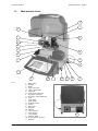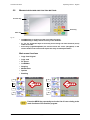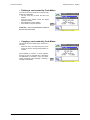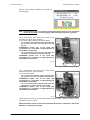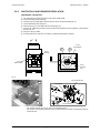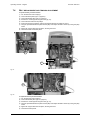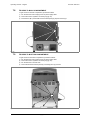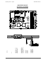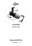
1
Operating manual
D434731XA
vers. 1.0
®
(c) 2008 SILCA S.p.A. - Vittorio Veneto
This manual is written by SILCA S.p.A.
All rights reserved. No part of this publication may be reproduced or used in any form or by any means (photocopying,
microfilm or other) without the written permission of SILCA S.p.A.
Edition: july 2008
Printed in Vittorio Veneto
by SILCA S.p.A.
via Podgora, 20 (Z.I.)
31029 VITTORIO VENETO (TV) - Italy
IMPORTANT NOTE: in compliance with current regulations relating to industrial property, we hereby state that the
trade-marks or trade names mentioned in our documentation are the exclusive property of authorized
manufacturers of locks and users.
Said trade-marks or trade names are nominated only for the purposes of information so that any lock for which our
keys are made can be rapidly identified.
INDEX
REFERENCE GUIDE .............................................................................................1
GENERAL ...............................................................................................................2
1
2
3
4
MACHINE DESCRIPTION ...............................................................................4
1.1
MAIN CHARACTERISTICS ................................................................................ 4
1.2
SAFETY ........................................................................................................ 5
1.3
MAIN WORKING PARTS .................................................................................. 6
1.4
TECHNICAL DATA .......................................................................................... 7
1.5
ACCESSORIES PROVIDED .............................................................................. 8
TRANSPORT ...................................................................................................9
2.1
PACKING ...................................................................................................... 9
2.2
UNPACKING ................................................................................................ 10
2.3
MACHINE HANDLING .................................................................................... 10
MACHINE INSTALLATION AND PREPARATION .......................................11
3.1
CHECKING FOR DAMAGE ............................................................................. 11
3.2
ENVIRONMENTAL CONDITIONS ..................................................................... 11
3.3
POSITIONING AND INSTALLATION .................................................................. 11
3.4
DESCRIPTION OF WORK STATION ................................................................. 12
3.5
GRAPHICS .................................................................................................. 12
“SET UP” AND USE OF THE MACHINE .....................................................13
4.1
USE OF THE CLAMP .................................................................................... 13
4.2
CUTTING BY ELECTRIC CONTACT ................................................................. 15
4.2.1
5
IMPROPER USE OF ELECTRIC CONTACT .................................................. 15
4.3
FITTING THE CLAMP TO THE MACHINE .......................................................... 16
4.4
CUTTER ..................................................................................................... 16
4.5
CHANGING THE CUTTER .............................................................................. 16
OPERATING GUIDE .....................................................................................17
5.1
INITIAL OPERATIONS .................................................................................... 17
5.2
MACHINE KEYBOARD AND FUNCTION BUTTONS ............................................. 18
5.3
COPY FROM ORIGINAL ................................................................................ 19
5.4
COPY WITH ADJUSTMENTS .......................................................................... 20
5.5
COPY FROM CUTTING CARD ........................................................................ 23
5.5.1
5.5.2
5.6
SPECIAL CASES ................................................................................ 29
LIMITED ACCESS TO DATA (PROTECTED SYSTEMS) .................................. 31
PC QUEUE ................................................................................................. 33
5.7
CODE MAKER ............................................................................................. 36
5.8
GAUGING ................................................................................................. 39
5.8.1
5.8.2
5.8.3
5.9
MAINTENANCE ....................................................................................... 45
5.9.1
5.9.2
5.9.3
5.9.4
5.9.5
5.9.6
5.9.7
5.9.8
5.9.9
5.10
CALIBRATE JAWS ................................................................................. 40
CALIBRATE CUTTERS .......................................................................... 44
CALIBRATE ADAPTERS ........................................................................ 44
OPTIC READER TEST ........................................................................ 45
MOTOR TESTS ................................................................................... 45
DIGITAL INLETS TEST ....................................................................... 45
DIGITAL OUTLETS TESTS ................................................................. 46
KEYPAD TEST .................................................................................... 46
DISPLAY TEST ................................................................................... 46
SERIAL PORT ..................................................................................... 47
MACHINE ZERO POINTS ................................................................... 47
PHOTOCELLS AND SENSORS REGULATION ................................. 50
OPTIONS ................................................................................................. 53
5.11
ENABLING ............................................................................................... 55
5.12
MESSAGES ............................................................................................. 56
5.12.1 ATTENTION MESSAGES ........................................................................... 56
5.12.2 ERROR MESSAGES ................................................................................. 57
5.12.3 ALARM MESSAGES ................................................................................. 58
6
CLEANING ....................................................................................................59
7
MAINTENANCE .............................................................................................60
7.1
TROUBLE SHOOTING ................................................................................... 60
7.2
MAINTENANCE OPERATIONS ........................................................................ 62
7.3
CUTTER REPLACEMENT ............................................................................... 62
7.4
BELT REPLACEMENT AND TENSION ADJUSTMENT .......................................... 63
7.5
CHECKING AND/OR REPLACING FUSES ......................................................... 64
7.6
ELECTRONIC CIRCUIT BOARD REPLACEMENT ................................................ 65
7.7
KEYBOARD/DISPLAY REPLACEMENT ............................................................. 66
7.8
ACCESS TO BACK COMPARTMENT ................................................................ 67
7.9
ACCESS TO BOTTOM COMPARTMENT ........................................................... 67
7.10
SENSOR REPLACEMENT .............................................................................. 68
7.11
PHOTOCELL REPLACEMENT ......................................................................... 70
7.12
BRUSH REPLACEMENT ................................................................................ 71
7.13
BATTERY REPLACEMENT ............................................................................. 71
7.14
WIN-TRANSFER PROGRAM ...................................................................... 72
8
DISPOSING OF MACHINE ...........................................................................73
9
ASSISTANCE ................................................................................................74
9.1
HOW TO REQUEST SERVICE ........................................................................ 74
Appendix 1 - ELECTRICAL DIAGRAM .......................................................... I - VIII
Appendix 2 - DECLARATION COMPLIANCE
Operating manual - English
Unocode 399 EVO
REFERENCE GUIDE
This manual has been produced to serve as a guide for users of the UNOCODE 399 EVO electronic keycutting machine. Read it carefully; it is essential if you wish to operate your machine safely and efficiently.
CONSULTATION
The contents of the manual are divided into sections relating to:
• Machine description Chapter ......................................................................1
• Transport and installation Chapters...............................................................
• Regulation and use Chapters ....................................................................
• Maintenance
Chapters ....................................................................
2-3
4-5-6
7-8-9
TECHNICAL TERMS
Common technical terms are used in this manual.
To assist those with little experience of keys and key-cutting, below is an illustration of the terms most
frequently used.
1
1
2
3
4
2
7
6
3
5
7
5
Fig. 1
1)
2)
3)
4)
5)
6)
7)
Head
Rim
Stop
Stem
Tip
Back
Cuts
Copyright Silca 2008
1
Unocode 399 EVO
Operating manual - English
GENERAL
UNOCODE 399 EVO has been designed in compliance to the European Community normative (CE).
From the design stage, risks for the operator have been eliminated in all areas: transport, regulation, cutting
and maintenance.
Further risks have been eliminated by means of protective devices.
The materials used to manufacture this machine and all its components are not hazardous.
USE
UNOCODE 399 EVO is designed for cutting keys of ferrous materials: brass, silver nickel, etc.
It must be installed and used according to the instructions indicated by the manufacturer.
If the key-cutting machine is used differently or for purposes different from those described in this manual,
the customer will forego any rights he may have over Silca S.p.A. Furthermore, unforeseen danger to the
operator or any third parties may arise from incorrect use of the machine.
INSTRUCTIONS MANUAL
The instructions manual provided with the machine is essential to its proper use and to carry out the
necessary maintenance.
We therefore recommend protecting the manual from damage in a safe sheltered place, easily to hand
for quick consultation.
INCORRECT USE
Operator negligence resulting in improper use of this machine or failure of the operator to observe the
instructions written in this manual. The manufacturer may decline all guarantees and responsibilities.
It is therefore essential to carefully read this operating manual.
IMPROPER USE OF ELECTRIC CONTACT
•
•
it is not permitted to cut ultralite anodized aluminium keys, plastic keys or any keys with materials
that do not have electrical conductivity by means of electric contact.
cuts cannot be repeated on the same side of the key when electric contact cutting is used.
FURTHER RISKS
No further risks will arise when properly using the UNOCODE 399 EVO.
PROTECTION AND SAFETY PRECAUTIONS FOR THE OPERATOR
UNOCODE 399 EVO is entirely built in compliance to the Machine Directives. The operations for which it
has been designed are easily carried out with no risk to the operator.
The adoption of general safety precautions and observation of the instructions provided by the
manufacturer in this manual eliminate all human error, unless deliberate.
UNOCODE 399 EVO is designed with features which make it completely safe.
• Power supply
UNOCODE 399 EVO is supplied with electricity by means of a grounded plug and differential switch.
• Pneumatic power
With compressed air.
• Start-up
The machine is turned on by means of a master switch that is located on the Unocode’s lower left back side.
• Maintenance
The operations to regulate, service, repair and clean the machine are structured in the simplest and safest
way possible. Parts that the operator can dismount cannot be incorrectly replaced therefore avoiding any
risks.
2
Copyright Silca 2008
Operating manual - English
Unocode 399 EVO
• Machine identification
The machine is provided with an identification label which includes the machine’s serial number (fig. 2).
Fig. 2
(*) see chap.8 "DISPOSING OF MACHINE", page 73.
Copyright Silca 2008
3
Unocode 399 EVO
1
Operating manual - English
MACHINE DESCRIPTION
UNOCODE 399 EVO is an electronic machine operating on two axes (3rd axis optional) with controlled
movement. Accurately studied, it adds a high degree of cutting precision to operating speed and ease
of use.
UNOCODE can be used in 3 different ways:
•
entering the key code directly by means of the machine keyboard
•
reading the key with a laser reader and reproducing it
•
linking to a PC and Silca software
Fig. 3
1.1
MAIN CHARACTERISTICS
• Movements
Movement of the two axes (X-Y) operates on ball screws activated by step motors, on rectified roller guides.
• Clamp
Standard four-sided clamp, specially designed to grip most flat keys.
• Working tool
Consists of a cutter in hard metal carbide, that is easily replaced.
Suitable to the type of work and speed rotation needed.
• Display
Placed on the front of the machine.
Its technical features and positioning make it highly practical in use.
• Laser reader
Designed to read cuts on keys to be reproduced.
4
Copyright Silca 2008
Operating manual - English
1.2
Unocode 399 EVO
SAFETY
• Protective shield
The transparent protective shield is designed to cover the working parts as completely as possible,
ensuring operator safety.
The shield (U) (fig. 5, page 6) must be raised in order to fit keys for cutting or carry out other operations.
Raising of the shield is controlled by a microswitch and disactivates the operating and movement
functions, including the cutter. A special message appears on the display to warn that the shield is not
closed.
To re-start the work cycle, place the shield in its original position and press START on the machine’s
keyboard.
• Emergency stops
The red emergency button (N) (fig. 5, page 6) placed on the right-hand side of the machine is used to
stop it immediately in the event of faulty operation or danger for the operator.
When the cause of the emergency has been eliminated, turn the button 45° clockwise to disactivate it.
Note: the operator is responsible for keeping the area around the button clear so that it can be reached
as quickly as possible.
• Laser warning
Regulations require that warning labels in the language to be used be attached to the laser reader, as
shown in fig. 4.
The adhesives are in the accessories kit provided (chap.1.5, page 8).
Fig. 4 - laser warning
• Cutter motor protection
The cutter motor is protected against overheating by a cut-out switch (located inside the motor) that will
automatically stop the motor if it reaches a certain temperature. Should the switch activate:
1) turn the machine off and disconnect the power supply cable.
2) contact Silca’s Technical Assistance Dept.
Copyright Silca 2008
5
Unocode 399 EVO
1.3
Operating manual - English
MAIN WORKING PARTS
U
L
E
I
E1
H
D
F
D1
F1
V
Q
Q1
C
B
S
T
N
P
O
R
Fig. 5
A - master switch
B - keyboard
C - display
D - clamp - cutter side
D1 - clamp - optical reader
E - clamp knob
E1 - optical reader clamp knob
F - key gauge - cutter side
F1 - key gauge - optical reader side
H - cutter
I - cutter shield
L - optical reader
N - emergency button
O - 3rd axis
P - IN/OUT port
Q - serial port
Q1- USB port
R - Y axis connector
S - X axis carriage
T - Y axis carriage
U - protective shield
U2 - vacuum systems connector
V - swarf tray
6
Copyright Silca 2008
A
Operating manual - English
1.4
Unocode 399 EVO
TECHNICAL DATA
Electricity supply:
230V-50Hz
Maximum absorbed power:
230V: 2 Amp. 250 Watt
cutter motor:
single phase and speed
cutter:
hard metal
Tool speed:
•
50Hz: 2370 rpm (+/- 10%)
Movements:
on 2 axes with ball screws activated by step motors, on rectified roller guides.
Possibility to add a 3rd axis to activate the optional tilting and rotating clamps.
Clamp:
universal 4 sided clamp to grip flat, car and cruciform keys
Runs:
X axis: 57 mm
Y axis:: 32 mm
Dimensions:
width: 450 mm depth: 600 mm height: 440 mm (with raised shield 680 mm)
Mass:
Kg. 38
Noise level:
sound pressure Lp(A) = 80 dB(A) (cutting iron keys)
77 dB(A) (cutting brass keys)
Copyright Silca 2008
7
Unocode 399 EVO
1.5
Operating manual - English
ACCESSORIES PROVIDED
UNOCODE 399 EVO comes with a set of accessories for its operation and maintenance (tools, hex
wrenches, fuses) supplied in a special tool kit comprising:
tool kit
10 mm spanner
D916657ZR
Z1 template
(regulating disk)
D931090ZR
13 mm spanner
Z20 setting template
tip stop bar
D912423ZR
2 Amp fuse
- delayed
D916658ZR
Z3 template
(regulating key)
D900754ZR
cutter release
rod
D901185ZR
4 Amp fuse
- rapid
Z4 serial test connector
D931082ZR
D916568ZR
10 Amp fuse
- delayed
belt tension
plate
2,5 mm allen key
D908726ZR
4 Amp fuse
- delayed
D908699ZR
Anti-tilting device
D910652ZR
6,3 Amp fuse
- delayed
D933777ZR
3 mm allen key
tip stop bar with notch
2 mm allen key
4 mm allen key
8
D906963ZR
19 mm
socket wrench
ø 1,7 mm steel pin
ø 1,2 mm steel pin
5 mm allen key
D906935ZR
slanted
brush
D909281ZR
serial cable 9/9
6 mm allen
key
laser
warning labels
D929095ZR
USB cable
Copyright Silca 2008
Operating manual - English
2
Unocode 399 EVO
TRANSPORT
The key-cutting machine is easily transported and is not dangerous to handle.
The packed machine should be carried by at least two people.
2.1
PACKING
The packing for UNOCODE 399 EVO is designed to ensure safe transportation and to protect the machine
and all its parts.
It comprises a pallet base (b) to which the machine is attached, and a cardboard box as a cover (a).
The machine is fixed to the base of the pallet with screwed down brackets that hold it firm into place. This
prevents the machine and its protective shield from any damage.
The closed packing is held in place by two straps which hold the cardboard box firmly on the pallet.
Symbols are printed on the outside of the cardboard box to give instructions and warnings for
transportation.
a
b
Fig. 6
Keep dry
Handle with care
This side up
Use no hooks
To prevent any damage to the machine it is advisable to save and use the brackets provided for future
transportation.
Copyright Silca 2008
9
Unocode 399 EVO
2.2
Operating manual - English
UNPACKING
To remove the machine from the packing box:
1)
2)
3)
4)
5)
6)
cut the straps with scissors and remove
raise the top part of the cardboard box
loosen the screws, both on the front and back brackets that hold the machine to the pallet
use the special spanner (provided in the tool kit), to loosen the nuts on the machine’s feet
remove the metal brackets and re-tighten the nuts on the feet.
check the contents in the box, that should comprise with the following:
1 UNOCODE 399 EVO key-cutting machine
1 set of documents, including: an operating manual, a spare parts list and a guarantee
1 power supply cable
1 tool kit
Note: we strongly recommend you keep the packing intact for future transportation
2.3
MACHINE HANDLING
When the UNOCODE 399 EVO has been unpacked, place it directly on its workbench; this operation
should be carried out by at least two people.
Take care to lift the machine firmly holding the base, and no other part.
ATTENTION: never lift the machine by holding the keyboard stand (fig. 7).
CORRECT!
INCORRECT!
Fig. 7
10
Copyright Silca 2008
Operating manual - English
3
Unocode 399 EVO
MACHINE INSTALLATION AND PREPARATION
The key-cutting machine can be installed by the purchaser and does not require any special skills.
It is supplied ready for use and does not need any special set up. However, the operator may have to
control a few things before operating the machine.
3.1
CHECKING FOR DAMAGE
UNOCODE 399 EVO is solid and compact and will not normally damage if transport, unpacking and
installation have all been carried out according to the instructions in this manual. However, it is always
advisable to check that the machine has not suffered any damage.
3.2
ENVIRONMENTAL CONDITIONS
To ensure that the best use is made of the key-cutting machine, it is important to place it in a well-aired
area which is not too damp.
The ideal conditions for the machine are:
temperature between 10°C and 40°C; relative humidity: approx 60%
3.3
POSITIONING AND INSTALLATION
1) Place the machine on a horizontal surface, solid enough to support the weight of 38 Kg.
- to work with ease, we suggest that the workbench be approximately the height of the operator’s
hip.
- it is important to leave clearance of at least 30 cm behind the machine and on each side to
ensure proper ventilation.
2) Ensure that the machines voltage is the same as that of the mains power supply, which must be
properly earthed and provided with a differential switch.
3) Connect the power supply cable to the power supply socket.
30 cm
30 cm
30 cm
100 cm
Fig. 8
Copyright Silca 2008
11
Unocode 399 EVO
3.4
Operating manual - English
DESCRIPTION OF WORK STATION
The machine needs only one operator, who has the following controls at his/her disposal (fig. 5, page 6):
• master switch placed on the back of the machine
• key-positioning clamp
• keyboard
• display
• emergency button
3.5
GRAPHICS
•
•
There is a prohibition warning label on the front side of the reader (fig. 9). This label must never be
removed.
Two laser warning labels must be attached to the optical reader (chap.1.2, page 5).
Do not use compressed air
for cleaning
laser warning labels
Fig. 9
12
Copyright Silca 2008
Operating manual - English
4
Unocode 399 EVO
“SET UP” AND USE OF THE MACHINE
USE OF THE CLAMP
1
2
3
4
1
2
3
4
4.1
V100
Clamp - cutter side
R100
Clamp - Optic Reader side
Fig. 10
The four-sided clamp ensures excellent grip on the keys placed on their back or profile sides (fig. 11).
• Keys with 1 or 2 cuts to reproduce by code should be fitted mainly on the A and/or B side of the clamp.
• When copying with the optical reader the key can be fitted to any side (A, B, C or D) of the clamp.
4
3
2
1
D
2
3
B
1
2
Fig. 11
3
4
A
4
-
D side
1
-
For keys to be cut by code the
side of the clamp on which to
place the key is shown on the
machines display.
For keys to be copied with the
optical reader the side of the
clamp to be used is at the
discretion of the operator.
To fit keys with tip stops on the
optic reader clamp, fit the bar
provided into the special
grooves (fig. 12).
C
-
A side
C side
B side
4
3
D
C
3
1
6
4
2
1
1
2
3
B
1
3
4
A
4
0
Fig. 12 - key stops
Copyright Silca 2008
13
Unocode 399 EVO
Operating manual - English
ATTENTION: the knobs are gauged so that they do not exert
too much pressure for closing (if pressure is too high they only
idle), which would damage the key and the parts of the clamp
(including the knob).
E
To turn the clamps:
With loosened handle (E) a light rotation of the clamp is
sufficient (gripping by the 2 jaws) to turn it to the required
side. Alignment is automatic and guaranteed by the mobile
pressure device (D5) (fig. 13).
D5
Fig. 13
Note: before starting to cut a key the V100 clamp gauge goes automatically to the idle position so there
is no need to lower it, but the R100 clamp gauge must be lowered manually.
USING THE PINS
Copying with the optical reader
For keys with narrow stems the pins must be placed between
the bottom of the clamp and the back of the key so that the
key protrudes sufficiently out of the clamp and therefore can
be properly read and cut.
If the key has a narrow stem and is also very thin, 2 pins must
be used (fig. 14).
Fig. 14
If the original key is broken, place a suitable sized pin in the groove of the keys stem so that it is properly
held in place and therefore can be copied (fig. 15).
Note: the diameter of the pin used for the original key must be the same as that of the pin used for the
blank key; only in this way will the two keys be locked in the same position.
pin
4
3
Attention: the pin
should be placed
vertically
B
3
2
1
C
1
2
2
1
A
3
D
4
4
broken keys
Fig. 15
14
Copyright Silca 2008
Operating manual - English
4.2
Unocode 399 EVO
CUTTING BY ELECTRIC CONTACT
The UNOCODE 399 EVO key-cutting machine is equipped with a low voltage electrical contact device
which permits the cutter to individualize the key blank as it approaches the cutter during the cutting phase
(fig. 16).
Fig. 16
This technical solution permits the operator to secure the key to the more appropriate side of the 4 faced
clamp (A, B, C or D) therefore improving the grip on the key and eliminating the need of pins and/or
adaptors.
With the electrical contact card enabled, depth calibration is automatically calculated when the cutter
touches the keys profile during the cutting process.
Electrical contact is guaranteed for keys in steel, brass, silver nickel, Zamak or iron (with or without nickelplating).
F1
F2
F3
F4
•
Press F2 to enable or disable the electrical contact function to read the key blank measurements.
The symbol * in the clamp field means that the key will be cut
reading the key blank measurements by electrical contact.
A red “X” on the electrical contact icon means that it has been
disabled.
Note: some cutting cards do not include electrical contact. In such cases the software
does not allow editing.
4.2.1
IMPROPER USE OF ELECTRIC CONTACT
It is not permitted to cut ultralite anodized aluminium keys, plastic keys or any keys with
materials that do not have electrical conductivity by means of electric contact.
ATTENTION:for these types of materials, insert standard cutting.
Cuts cannot be repeated on the same side of the key when electric contact cutting is
used.
All data cards provided by Silca are in the machine’s memory. The cards are enabled or disabled for code
cutting by electric contact at Silca’s discretion.
Copyright Silca 2008
15
Unocode 399 EVO
4.3
Operating manual - English
FITTING THE CLAMP TO THE MACHINE
To remove the clamp unit:
-
loosen the grub screw (D2) (fig. 17) and slide the
clamp out of the dovetail guide.
To install the clamp unit on the machine:
-
slide the clamp into the dovetail guide, pushing it all
the way in, then secure it by tightening the grub
screw (D2).
These instructions refer exclusively to the standard
clamp (V100). For the use of optional clamps please
refer to the instructions provided along with them.
Fig. 17
D2
4.4
CUTTER
The majority of keys utilize the standard cutter for code cutting. Only in certain cases some special keys
with particular type cuts require different cutters.
To change the cutter see chapter 4.5.
4.5
CHANGING THE CUTTER
1) raise the protective shield.
2) remove the cutter protective shield (i) by loosening the screw (i2).
3) slide the cutter release rod (X) into the hole located on the left side of the machines cutter shaft chassis
(fig. 18).
4) loosen the cutter locking nut (turning it clockwise) with the19 mm socket wrench (X1) provided with the
machine.
ATTENTION: the thread is left-handed.
5) replace the cutter, then tighten the nut (turning it counter-clockwise) and remove the rod from its hole.
6) place the cutters protective shield (i) back into position securing it with the screw (i2).
X
i2
i
X1
Fig. 18
ATTENTION: when replacing a worn cutter with a new one or with a re-sharpened cutter consult
chap.5.8 "GAUGING", page 39.
16
Copyright Silca 2008
Operating manual - English
5
Unocode 399 EVO
OPERATING GUIDE
Introduction
The Operating Guide below explains how to use the UNOCODE 399 EVO without a Personal
Computer.
All operations to manually use the key-cutting machine are explained step by step.
The programs available for Personal Computers connected to the key-cutting machine are able to
transmit data for cutting, reading or decoding keys.
Programs for Personal Computer eliminate manual procedures of certain functions, once the data has
been transmitted to the machine it bypasses some of the operating guides screens.
When the UNOCODE 399 EVO is used with a Personal Computer, the operating guide does not change
its displays logic, with the exception of all the screens that are rendered unnecessary.
5.1
INITIAL OPERATIONS
When the key-cutting machine has been placed on its workbench and connected to the mains
(cap.3.3, page 11), proceed as follows:
1) make sure that the emergency button is not turned on.
2) turn the machine on by means of the main switch that is located on the back of the machine.
3) to check or alter the parameters for use of the machine, consult the "OPTIONS" menu (chap.5.10,
page 53).
When the machine is turned on the display shows the following screen:
Fig. 19
Besides the first 4 icons relating to the main functions, listed on the left, the following information
appears:
•
Name of the key-cutting machine
•
Serial number of the key-cutting machine
•
SW version: machine program version
•
DB version: version of the cutting card Database on board the machine
•
Date
•
Time
•
Flashing word MENU (press MENU to view the other main functions)
Copyright Silca 2008
17
Unocode 399 EVO
5.2
Operating manual - English
MACHINE KEYBOARD AND FUNCTION BUTTONS
Function key
Arrow key
Menu key
Fig. 20
•
The MENU key is used to view the list of main functions.
The MENU key is always active from any of the windows.
• F1 - F2 - F3 - F4 function keys are used only for accessing one of the functions (icons)
listed on the side.
•
Arrow keys (right/left/up/down) are used to move the cursor (navigation) in the
various fields on the screen that require the entry of values/parameters.
Main menu functions
• Copy from Original
• Copy card
• PC queue
• CodeMaker
• Gauging
• Maintenance
• Options
• Enabling
F1
F1
F2
F2
F3
F3
F4
F4
Press the MENU key repeatedly to view the list of icons relating to the
main functions of the machine program.
18
Copyright Silca 2008
Operating manual - English
5.3
Unocode 399 EVO
COPY FROM ORIGINAL
In the initial screen press F1 to use the function.
This function is used to make a direct copy from the
key, without further stages.
The “Copy from Original” window shows certain data
and icons:
•
Cutter to use (cannot be edited)
•
Clamp to use (cannot be edited)
•
Stop position (settings go from 0 to 6; other
values can be written but will not be confirmed)
•
Pieces = 1 / 1(up to 999 pcs. can be set)
Minimum distance:
The number shown on the machine’s display
represents the X axis distance between the key blank
shoulder and the beginning of the first cut.
This function is extremely important with keys that
require cuts on both sides as it ensures precise
positioning on the key 2nd side.
Gauge
0
1
2 3
4
Stop 2
A
The set figure is 50 hundredths of a mm, which can be
varied:
• min.0 - max. 99 hundredths of a mm.
ATTENTION: settings that are too high may render
precise cuts impossible, with the following message
on the display:
MIN. Parameter of
DISTANCE FROM STOP
is incompatible with
selected card!
Note: the icon in the lower left corner of the menu can be activated by the F4 key (see
chap.5.4 "Copy with adjustments", page 20).
Set the number of pieces to be cut, the type of Stop to use (up/down arrow keys to move and numerical
keys for entry). As illustrated in the figure, with Stop 0 and pieces 1, fit the key blank into the clamp on
the cutter side and the original key into the clamp on the reader side. Lower the right-hand clamp gauge
and press START to begin.
Note: after placing the original key in the r/h clamp,
remember to lower the gauge. If this is not done, when
reading starts the machine will stop and show the
following message on the display:
In this case lower the gauge and press START to
continue.
Copyright Silca 2008
19
Unocode 399 EVO
Operating manual - English
First the display will show:
and then:
-
5.4
Press STOP to confirm the end of the operation.
Press ENTER if you wish to cut other keys.
COPY WITH ADJUSTMENTS
In this mode an original key is copied in 3
stages:
• Reading
F1
F2
• Setting up of adjustments
• Cutting
F3
The icon in the lower left corner of the menu
can be activated by the F4 key.
Press F4 again to return to the “Copy from
Original” menu.
When you click on F4 the screen changes:
- The icon/figure of the original key placed in the
right/hand clamp (reader side) and an empty
left-hand clamp (cutter side:
A box appears containing adjustments in depth
and spaces.
- Press START to start reading.
F4
F1
F2
F3
F4
20
Copyright Silca 2008
Operating manual - English
Unocode 399 EVO
Note: after placing the original key in the r/h
clamp, remember to lower the gauge. If this is not
done, when reading starts the machine will stop
and show the following message on the display:
In this case lower the gauge and press START
to continue.
When reading is finished, to enter the
adjustments, use the “up/down” arrow keys over
the fields (Depths and Spaces) in which the
adjustments are to be made:
•
•
•
Press F1 to get positive values (+).
Press F2 to get negative values (-).
Press F3 to cancel the set adjustments.
Adjustments possible for Depth (-30 to
+30 hundredths of a millimetre):
-
F2
One value (positive or negative) raises or lowers all cuts.
Adjustments possible for Spaces (-30 to
+30 hundredths of a millimetre):
-
F1
One value (positive or negative) moves all the
cuts (from the stop) to the right or left.
F3
F4
Warning! The presence of this symbol indicates that adjustments to the card
have been applied!
Copyright Silca 2008
21
Unocode 399 EVO
Operating manual - English
Press ENTER to view the “new” key with the
adjustments made.The display will show:
- a black outline of the original key (key read).
- a blue outline of the key to be cut, with the adjustments made.
Fit the key blank into the clamp on the cutter side
and secure. Lower the safety shield and press
START to proceed with cutting.
Warning! The presence of this symbol indicates that adjustments to the card
have been applied!
First the display will show:
and then:
•
•
22
Press STOP to confirm the end of the operation.
Press ENTER if you wish to cut other keys.
Copyright Silca 2008
Operating manual - English
5.5
Unocode 399 EVO
COPY FROM CUTTING CARD
From the initial screen press F2 to use the function.
One part of the machine’s internal memory is used as a cutting card archive.
A cutting card is a database of “Spaces”, “Depths” and cutting angles for all the keys Silca considers
can be taken into consideration.
SILCA and USER cutting cards can be selected by pressing F1.
• SILCA cutting cards
F1
SILCA cards are found in:
- Paper catalogues
- Electronic catalogue
- Silca Key Programs
F2
Certain parameters on SILCA cards can
be edited, but the adjustments CANNOT
BE SAVED in the machine memory.
The number of SILCA cards is periodically
increased with the “Silca Code Program”
update, which can be purchased separately.
Through the Silca Code Program the user can
update the program and data on the machine.
F3
F4
• USER cutting cards
Cards customized using Silca Key Programs on
the PC and sent to the machine. They can be:
- Created with Code Maker of SKP
- Silca SKP cards with certain parameters
edited.
Certain parameters on USER cards can be
edited and editing CAN BE SAVED in the
machine memory.
F1
F2
F3
F4
•
Press F3 to view the list of User cutting cards.
Operational keys:
Up/Down arrows: to scroll cards
ENTER:
to select
CLEAR:
to delete selected card
Copyright Silca 2008
23
Unocode 399 EVO
Operating manual - English
• CODEMAKER cutting cards:
Customized cards created using CODE MAKER
on the machine.
F1
F2
F3
F4
•
Press F3 to view a list of CodeMaker cards.
EXAMPLE: Copy from SILCA cutting Card
1) Digit the card number (e.g.: 50):
Press ENTER, the display shows:
.......
The dots shown represent possible cuts. The same
card can be used for a number of keys with a different
number of cuts.
If a key is used with fewer cuts than the dots on the
display, just digit a partial combination.
2)
•
•
•
24
Digit the cuts.
Single side
Double symmetric
Double asymmetric
Side 1
Side 1x2
Side 1 / Side 2
Copyright Silca 2008
Operating manual - English
Unocode 399 EVO
Card No
Symbols associated to cutting depths
Clamp to use
Adapter if applicable
Number of cuts per side for current key
Cutting
Symbols allowed
Fig. 21
•
Press F1 to consult the cutting parameters
on the card.
F1
Key blank measurements
Cutting angle
Key stop
Symbols associated to cutting depths
Cutting spaces
Measuring unit
Base of the cuts
Press STOP to exit.
•
Press F2 to set up manual adjustment of
cutting depths and spaces.
F2
Copyright Silca 2008
25
Unocode 399 EVO
•
•
•
Operating manual - English
Press F1 to set positive values (+).
Press F2 to set negative values (-).
Press F3 to cancel the adjustments made.
Adjustments possible for depth (-30 to
+30 hundredths of a mm):
-
one value (positive or negative) raises or lowers all cuts.
F1
F2
F3
Adjustments possible for spaces (-30 to
+30 hundredths of a mm):
-
one value (positive or negative) moves all
cuts (from the stop) to the left or right.
F4
Press STOP to exit.
Warning! The presence of this symbol indicates that adjustments to the card
have been applied!
3) Press ENTER to continue.
Clamp: V100/*
The special symbol (asterisk) means that the cuts will be
made by electric contact therefore it is unnecessary to select the clamp side.
Pos.: 0
Place the key to be cut into the V100 clamp (cutter side)
using the stop that is shown.
Cutter: U01W
cutter to use.
Pieces:
enter the quantity of keys to be cut (max.999).
26
Copyright Silca 2008
Operating manual - English
Unocode 399 EVO
Modify cutting method
F1
•
By pressing F1 it is possible to view the cutting method set by Silca for the card and to modify it when
possible (chap.5.5.1, page 29).
Use of Electric Contact
F2
•
Press F2 to enable or disable the electrical contact function to read the key blank measurements.
The symbol * in the clamp field means that the key will be cut reading the
key blank measurements by electrical contact.
A red “X” on the electrical contact icon means that it has been disabled.
Note: some cutting cards do not include electrical contact. In such cases the software
does not allow editing.
F3
•
Press F3 to vary the setting for the value of the key blank measurements.
Note: when electrical contact is used it is advisable to set key blank measurements that
are the same as those of the key to be cut.
Copyright Silca 2008
27
Unocode 399 EVO
Operating manual - English
4) proceed with cutting the first side by pressing the
START key.
5) Turn the key and cut the second side if the key is
symmetrical, as in this case. Press START.
When the last side of the last key has been cut, the
screen shows:
28
Copyright Silca 2008
Operating manual - English
5.5.1
Unocode 399 EVO
SPECIAL CASES
• Cutting a key with two asymmetrical sides
Operational keys: use the [up/down] arrow keys to be able to visualize all data.
Proceed with the cutting process.
• Cuts not allowed
When the machine is used manually with certain data cards, it may not be possible to carry out certain
entered combinations. This happens when the cutting depths are not compatible in the order the user
entered the possible cuts.
Example:
After entering the cutting combination the Silca
software calculates the validity of the data. If there is
inconsistency, when the ENTER key is pressed the
following message appears:
NON-FEASIBLE
COMBINATION
This message is explained below.
The reason for the conflict between certain cuts is
explained simply in the case shown.
With regard to the cut that originated the message
<NON-FEASIBLE COMBINATION> it can be seen
that between the two deep cuts (8) and the constant
angle (100°) the intermediate cut (0) would be
removed.
This happens when the cutting angle N (Normal) is not
made variable by means of the type of cut L (Laser).
?
8 0
8 4
α
α
α
6
α
Fig. 22
The new drawing of the key shows how for the same
cutting process (80846) the cutting angles are
automatically calculated by the conjunction of the
cutting base with a straight line.
This aspect, admissible with certain car keys, is more
commonly known as ‘the ideal cutting line’.
8
0
α β
8 4 6
β
γ δ
α
ATTENTION: in this example it can be seen that the ß
angle is less than 45°. This could cause serious
problems with a lock, making it difficult or impossible
to place the key into the cylinder or remove it.
Fig. 23
Control of the combinations in the Options menu can in any case be disabled.
Copyright Silca 2008
29
Unocode 399 EVO
Operating manual - English
• Changing the Types of Cut
All the data cards provided by Silca have the type of cut pre-set according to the original parameters.
The types of cut possible with UNOCODE 399 EVO are: Normal, Flat, Laser and Vertical.
EXAMPLE OF HOW TO CHANGE THE TYPE OF CUT:
-
Press F1 key.
F1
Current cut type
Cut type set by Silca
as original
Feasible and selectable
options for the
selected card
All the technical data regarding the types of cuts stored in the machine’s memory can be changed
according to the user’s requirements.
ATTENTION: for certain cutting methods the standard cutter U01W must be replaced with a specific
cutter.
N
NORMAL
For conventional car and door keys.
P
FLAT
Mainly used for car keys where the cut edges are rounded to
facilitate the movement of the blades when the key is put into
the lock.
L
LASER
Conjunction of the cutting angles is determined automatically
by the machine, allowing cuts to be made with variable angles;
this facilitates the smooth entry of the key into the lock,
prolonging the working life of the key.
V
VERTICAL
V
30
Necessary for special keys with small bits (Silca art. FO19P,
FO21P...) where a special cutter is required.
When this cutting method is used a special angled cutter is
needed.
Copyright Silca 2008
Operating manual - English
Unocode 399 EVO
• Changing the cutter
For certain cutting methods the standard cutter U01 must be replaced with a specific cutter.
EXAMPLE WITH
FO21P key:
Note: replace the cutter according to the instructions in chap.7.3, page 62.
• Use of Adaptors
Some of the data cards provided by Silca may show a new parameter (Adapt.:B...) which indicates the
type of accessory that is needed to cut the key in question (fig. 21, page 25).
See the leaflet included with thee UNOCODE 399 EVO machine.
5.5.2
LIMITED ACCESS TO DATA (PROTECTED SYSTEMS)
Silca has predisposed limited access to some of the data in the Database, in compliance with
agreements with some makers. Limitations apply to:
- DATA CARD: If the key-cutting card is protected, access is denied.
Gain access to protected data in the following way:
- request the maker’s authorization.
- communicate to Silca:
- The key-cutting machine SERIAL NUMBER
- The ACTIVATION CODE
- Key-cutting Machine ID
Silca will issue a Password to enter in order to enable
key-cutting of the protected system.
Example: Silca provides a protected data card No
2211.
When card 2211 is selected from menu F1 the
following appears on the screen:
When authorization has been received from the
maker, apply to Silca for a password, providing the
following information:
- Key-cutting machine serial No 1170145634567
Read the serial number of the ID plate located on the
back of the key-cutting machine or on the initial
screen on the display.
- Machine ID 12345
Visible in the password box.
- ACTIVATION Code WUCSC02211
shown ONLY when access to protected data is attempted.
Once obtained, enter the password on the Password
line, as shown in the example given.
Copyright Silca 2008
31
Unocode 399 EVO
Operating manual - English
If the correct password has been entered, the screen
shows:
The password can be saved so that it need not be
entered whenever the protected data card is used, or not
saved so that access is limited only to the person in
possession of the password.
32
Copyright Silca 2008
Operating manual - English
5.6
Unocode 399 EVO
PC QUEUE
• USE OF THE MACHINE WITH A PERSONAL COMPUTER
Taken for granted that the user is in possession of some Silca software, the following are the
possibilities available.
The ‘Silca Code Program’ makes it possible to carry out searches by code for cutting data and to store
the information in a special work queue (or file).
This is a special function which has been created to help those users who wish to work with a number
of simultaneous searches. After having carried out a code search, the information is simply filed in the
special work queue then everything is transferred to the UNOCODE 399 EVO.
The information transmitted by the Personal Computer cannot be altered manually. Each line
transmitted corresponds to a stage in the cutting process for one or more keys.
As described above, for each cutting process transmitted the number of pieces to be cut is set¸ a ‘+’ sign
shows when the cycle is finished.
The ‘+’ sign warns the operator that the last cutting operation has been carried out.
Should a work queue be interrupted, turn off the UNOCODE 399 EVO. When the machine is turned on
again and the <PC queue> is called up, the list reappears, starting from the first line.
From the initial screen press F3 to enable the function.
• PC queue
The data received from the PC is presented as a list:
- No. of jobs received
- Indirect cutting code
- Silca cutting card No.
- No. of pieces to be cut.
By means of the arrow keys (up and down) the user
can select the job to be done and confirm with the
ENTER key.
•
The “+” sign indicates that the set key has been
cut.
•
The “-” sign indicates that the set key has not
been cut yet.
card nr.
pieces
Data for the job, received from the PC program, CANNOT be edited manually (except for
Electrical contact and Key blank measurements).
For example, the following will appear on the display:
F1
F2
•
Press F1 to see the cutting parameters on the card in question.
Copyright Silca 2008
33
Unocode 399 EVO
Operating manual - English
F2
•
Press F2 to view any manual adjustments set up by the PC program.
Press ENTER to continue, the display will show:
F1
•
Press F1 to view the cutting method set up by Silca for the card in question.
1
F2
2
•
Press F2 to enable or disable the electrical contact function for reading the key blank measurements.
1 - A red “X” on the electrical contact icon means that it has been disabled.
2 - The symbol (*) in the clamp field means that the key will be cut reading the key blank measurements
by electrical contact.
Note: some cutting cards do not include electrical contact. In such cases the software does not allow
editing.
Note: when electrical contact is used it is advisable to set key blank measurements that
are the same as those of the key to be cut.
34
Copyright Silca 2008
Operating manual - English
Unocode 399 EVO
F3
•
Press F3 to vary the setting for the value of the key blank measurements.
Note: when electrical contact is used it is advisable to set key blank measurements that
are the same as those of the key to be cut.
When the key blank has been fitted into the clamp on the cutter side and the safety shield is down, press
START. The cutting process starts.
The display will show:
When the first side has been cut, the display will show:
-
Raise the safety shield and position the second side of
the key to be cut.
Lower the safety shield and press START, the display
will show:
When the second side has been cut, the display will show:
•
•
Press STOP to finish the job.
Press ENTER to continue cutting other keys with the
same cuts as the key just finished.
Copyright Silca 2008
35
Unocode 399 EVO
5.7
Operating manual - English
CODE MAKER
The Code Maker function is used to create a new cutting card with user-definable cutting parameters.
From the initial screen press F4 to enable the
function.
The display shows a list of user-created cards (on
F1
a new machine the display is empty).
F2
F3
F4
The functions included in CodeMaker are represented by the 4 icons on the left.
•
Create new card (press F1 to start)
•
Edit a user-created card (press F2 to start)
•
Delete card created (press F3 to start)
•
Copy a user-created card (press F4 to start)
NOTE: Creating of new cards is allowed for two key types:
-
SINGLE side
DOUBLE SYMMETRICAL side
• Creating a new card with Code Maker
Assign a name (description) to the new card. All
data except the card number can be edited.
Step 1
Operational keys (in Description field):
F1
F2
Left and right arrows: to move the cursor
SHIFT+ENTER:
to insert a space
F3
CLEAR:
to delete a character to the left of
the cursor (Backspace)
SHIFT + CLEAR: to delete a character to the right
of the cursor (Del)
F4
Once the values have been entered press F1 to
continue. The display will show:
F1
Step 2
This display screen can be used to edit:
• Type of cut (see chap. 5.5.1)
• Cutter (set automatically in relation to the type
of cut)
• Angle (can be set for types of cut different from
“V”)
Note: press F2 to go back to the previous screen.
F2
F3
F4
When editing is complete, press F1 to continue.
36
Copyright Silca 2008
Operating manual - English
Unocode 399 EVO
Step 3
Enter the depth symbols (numbers or letters) and
associate them to the required cutting depth.
Press ENTER to confirm the value and go from
one field to another. All measurements are
expressed in hundredths of a millimetre or
inches, according to the settings in the machine
Options (cap.5.10, page 53)
F1
F2
Note: press F2 to go back to the previous
screen.
When editing is complete, press F1 to continue.
number of
depths entered
depths
symbols associated
with depths
Step 4
Enter the cutting space values, from the key stop to the centre of the first cut, then from the centre of
the first cut to the centre of the second cut, and so on. The cut bases can vary from 0 to 200, which is
the width of the base of the cut. All measurements are expressed in hundredths of a millimetre or inches,
according to the settings in the machine Options (chap.5.10, page 53)
Note: press F2 to go back to the previous screen.
TIP stop
HEAD stop
When editing is complete, press F1 to continue. The
display will show:
•
•
Press ENTER to confirm editing.
Press STOP if you wish to return to the main menu
without saving the data.
• Editing a card created by Code Maker
This function is used to edit a card previously created by Code Maker. Use the arrow keys to select the
card to be edited.
- Press F2 for the editing controls.
- Follow the procedure described above.
Copyright Silca 2008
37
Unocode 399 EVO
Operating manual - English
• Deleting a card created by Code Maker
This function is used to eliminate a card previously
created by Code Maker.
• Use the arrow keys to select the card to be
deleted.
• Press F3 for the deletion control. The display
appears as follows:
• Press ENTER to confirm deletion.
• Press STOP to stop the operation.
F3
ATTENTION: when a card is deleted the number of
that card cannot be reused.
• Copying a card created by Code Maker
This function is used to speed up the creation of a
new card.
• Select the card to be copied and press F4; the
display will show a message asking whether to
proceed.
Press ENTER to proceed. A screen appears
showing the card to complete with a description
and adjustment, if necessary, of any key and/or
cutting parameters (see paragraph “Creating a
card with Code Maker”).
38
Copyright Silca 2008
F4
Operating manual - English
5.8
Unocode 399 EVO
GAUGING
The following components on the machine have a specific ‘self-setting’ procedure with the use of
regulating templates (chap.1.5 "Accessories provided", page 8):
- CLAMPS
- CUTTERS
ADAPTERS provided as optionals do not require calibrating. However, if necessary adjustments can be
made to the cutting data, according to the procedures described in chap.5.4 "Copy with adjustments",
page 20.
In the circumstances listed below (see events) it may be necessary to re-set one or all of the clamps
and/or cutters that the user has in possession. This operation is semi-automatic and requires close
attention to the instructions listed below.
MACHINE
ZEROES
EVENT
CALIBRATION
CLAMPS
CUTTERS
Replacement of photocells
YES
YES
NO
Electronic board replacement
YES
YES
NO
Replacement of the Optical Reader unit
NO
YES
NO
Replacement of sensors
YES
YES
NO
Replacement of the cutter shaft
YES
YES
NO
Replacement of the ball screws
YES
YES
NO
Clamp replacement Cutter side
(with a new one of the same type)
NO
NO
NO
Clamp replacement Lector side
(with a new one of the same type)
NO
NO
NO
Re-sharpening of existing cutter and/or cutter
replacement (with a new one of the same type)
NO
YES
YES
Installation of optional clamps
NO
YES
(if applicable)
NO
From the initial screen press MENU then F1 to
enable the function.
F1
F2
F3
F4
•
Clamps ->
•
Cutters ->
•
Adapters ->
Copyright Silca 2008
39
Unocode 399 EVO
5.8.1
Operating manual - English
CALIBRATE JAWS
Press F1 to access the list of clamps.
Use the up/down arrow keys to select clamp 3V100, then press ENTER.
F1
F2
F3
The display will show:
Some manual adjustments can be made from this
screen.
ATTENTION: adjustments are made only if necessary
and only after automatic gauging.
Press START to proceed with automatic gauging; the
display will show:
ATTENTION: before
operating flow below.
gauging
carefully
read
the
Press ENTER, the display will show:
Make sure the U01W standard prismatic cutter is
installed.
Z3
Press ENTER, the display will show:
- Fit the test key blank (Z3 template) into side A of the
left-hand clamp (Stop 0).
Fig. 24
-
40
Lower the safety shield and press START. When cutting is complete the display will show:
Copyright Silca 2008
Operating manual - English
Unocode 399 EVO
Fit the test key (Z3 template) cut and carefully cleaned
into side A of the right-hand clamp (Stop 0).
-
Lower the safety shield and press START. When
reading is complete the display will show:
-
Raise the safety shield, remove the Z3 template from
the right-hand clamp and replace with a carefully
cleaned Z20 template (Stop 0).
-
Lower the safety shield and press START.
After an intermediate message “Reading template
measurements” the display will show:
•
•
Press ENTER to confirm the data.
Press STOP to exit without confirming.
Z3
-
Fig. 25
Fig. 26
Note: acceptable value range: +/- 40 hundredths
of a millimetre.
Press ENTER, the display will show:
As the Z20 template is already on the reading clamp,
just press START.
Copyright Silca 2008
41
Unocode 399 EVO
Operating manual - English
After an initial message of “Reading” the display will
show (example):
Note: discrepancies in X of +/-0.03 mm from theoretical measurements can be considered
normal. Press STOP to confirm gauging without making mechanical regulations.
The X measurement read should be the same as the
theoretical one (value= 400 in brackets).
If not, raise the safety shield and proceed as follows:
•
For an X value lower than 400, loosen the grub screw
(P1) and use a hex. wrench to tighten the screw (P2)
(fig. 27).
ATTENTION:a quarter turn of the screw (P2)
corresponds to a movement of approximately 19
hundredths of a millimetre.
•
For an X value above 400, loosen the grub screw (P1)
and use a hex. wrench to loosen the screw (P2).
ATTENTION: quarter turn of the screw (P2)
corresponds to a movement of approximately 19
hundredths of a millimetre.
Fig. 27
P2
P1
The Y measurement read should be the same as the
theoretical one (value = 500 in brackets).
If not, proceed as follows:
•
For a Y value lower than 500, loosen the grub screw
(P3) and use a hex. wrench to tighten the screw (P4).
ATTENTION:a quarter turn of the screw (P4)
corresponds to a movement of approximately 19
hundredths of a millimetre.
•
For a Y value above 500, loosen the grub screw (P3)
and use a hex. wrench to loosen the screw (P4).
ATTENTION:a quarter turn of the screw (P4)
corresponds to a movement of approximately 19
hundredths of a millimetre.
P3
P4
Fig. 28
Tighten the grub screw (P3), lower the safety shield and press START; repeat the operation until the
right values of X and Y are set.
When the X and Y values are the same as the theoretical ones (in brackets or with errors
between +/- 0.03mm) press STOP.
42
Copyright Silca 2008
Operating manual - English
Unocode 399 EVO
The display will show:
-
•
Press ENTER to confirm the gauging values just
read.
Press STOP to go back to the previous step without
confirming the gauging values.
Press ENTER to go back to the gauging menu for the
3-V100-Standard clamp.
Note: besides automatic gauging, the operator can make manual adjustments by entering
the values in the X and Y parameters.
ATTENTION:such adjustments (if necessary) are to be entered only after automatic
gauging, if applicable.
Adjustments can be made within a range of +30 and -30 hundredths of a mm.
- To adjust clamps and adapters the positive values of X will give the result shown.
- To adjust cutters, clamps and adapters the positive values of Y will give the result shown.
•
Press STOP to go back to the main menu.
Copyright Silca 2008
43
Unocode 399 EVO
5.8.2
Operating manual - English
CALIBRATE CUTTERS
From the Gauging menu press F2 to enable the
cutter gauging function.
F1
With the up/down arrow keys select the U01W
standard cutter and press ENTER.
F2
F3
The display will show:
F1
F2
•
•
The positive or negative values are obtained by
pressing F1 (+) or F2 (-).
Press F3 to cancel the adjustments made.
F3
Adjustments can be made within a range
between +30 and –30 hundredths of a mm.
5.8.3
CALIBRATE ADAPTERS
From the Gauging menu press F3 to enable the
Adapter gauging function.
F1
Use the up/down arrow keys to select the
adapter to be gauged and press ENTER.
F2
F3
The display will show:
• Use the “right or left” arrow keys to change the
adjustment field (X or Y).
• Positive or negative values are obtained by
pressing F1 (+) or F2 (-).
• Press F3 to cancel the adjustments made.
Adjustments can be made within a range
between +30 and -30 hundredths of a mm.
44
F1
F2
F3
Copyright Silca 2008
Operating manual - English
5.9
Unocode 399 EVO
MAINTENANCE
From the initial screen press MENU then F2 to enable the function.
Use the up/down arrow keys to select the option and
press ENTER, or directly press the key relating to the
option number.
5.9.1
OPTIC READER TEST
Lower the safety shield and hold down the START
button.
The status of the optic reader will go from --- to ON.
If it goes to OFF it is faulty. The comparison levels
will indicate values between 140 and 240 to the right
and 50 and 90 to the left.
5.9.2
•
If the value to the right is 255 it means the
reader is faulty or the light beam is interrupted
(check that there are no objects in the way of
the conical slide). If the value to the left is 0 the
reader is inactive. Contact Silca after-sales
service.
•
If the value to the left is higher than 90 clean
the reader glass slide with a clean cloth.
•
If the value remains over 90 (or lower 50)
contact Silca after-sales Service.
MOTOR TESTS
Read the instructions on the display carefully and
check that the carriage (or optional clamp in the case
of B) for the axis involved moves.
ATTENTION: during this test function all end of run
controls are disactivated; avoid moving the carriage
up against its mechanical stops.
5.9.3
DIGITAL INLETS TEST
-
Lift and lower the protective shield checking that
the machine’s display indicates OFF (with shield
raised) to ON (with shield lowered).
Note: if the ON/OFF transition is not made, contact
Silca’s Technical Assistance Dept.
-
Use any metal conductor to contact clamp to
cutter, checking that the machine’s display indicates OFF to ON.
Note: if the ON/OFF transition is not made, contact
Silca’s Technical Assistance Dept.
Jaw acknowledgement: operational only with electrically connected device.
Copyright Silca 2008
45
Unocode 399 EVO
Operating manual - English
This test can be carried out only when an automatic
feeder (or other optional component) is installed on
the machine.
5.9.4
DIGITAL OUTLETS TESTS
Use the up/down arrow keys to move onto the
required field, lower the safety shield and press
START; it will go from OFF to ON.
- In the case of the cutter, the motor will also start.
- In the case of the cutting side or reading lamp, the
one in question will illuminate momentarily.
Note: if this is not so, contact Silca’s Technical
Assistance Dept.
This test (Exit...) can be carried out only when an
automatic feeder (or other optional component) is
installed on the machine.
5.9.5
KEYPAD TEST
Press all keys (except STOP) one at time and verify
that for every key pressed the display shows the
same key circled. Press STOP at the end of the
operation to quit the test.
Note: if this is not so, contact Silca’s Technical
Assistance Dept.
5.9.6
DISPLAY TEST
Press ENTER repeatedly to verify changes in the
background colour.
Note: if no changes are noticed, contact Silca’s
technical assistance department.
Press STOP to exit Test.
46
Copyright Silca 2008
Operating manual - English
5.9.7
Unocode 399 EVO
SERIAL PORT
Check that the machine’s display indicates OFF.
Fit the special (Z4) serial test connector (accessories
provided) to the machine’s serial port.
Press START and check that the machine’s display
indicates OFF to ON.
Note: if the ON/OFF transition is not made, contact
Silca’s Technical Assistance Dept.
5.9.8
MACHINE ZERO POINTS
With the use of regulating templates (chap.1.5 "Accessories provided", page 8) the machine provides a
‘self-setting’ procedure. These procedures must be carefully carried out following the descriptions and
illustrations indicated below.
The table below indicates the situations where the Machine Zeroes function must be activated.
MACHINE ZEROES
EVENT
CALIBRATING
CLAMPS
CUTTERS
Replacement of
photocells
YES
YES
NO
Replacement of
the electronic board
YES
YES
NO
Replacement of
the Optical Reader unit
NO
YES
NO
Replacement of sensors
YES
YES
NO
Replacement of the cutter shaft
YES
YES
NO
Replacement of the ball
screws
YES
YES
NO
Fit the template (Z1) in the place of the cutter; (to
remove the cutter read the instructions in chap.7.3).
Copyright Silca 2008
47
Unocode 399 EVO
Operating manual - English
Press ENTER to continue, the display shows:
Read the instructions on the display and fit the Z20
template into the cutter side of the clamp, with Stop
0 as the reference.
Fig. 29
Lower the gauge and press ENTER to continue.
The display shows:
Read the instructions on the display, move the
carriages manually so that the Z20 template is taken
into contact with the Z1 template (fig. 30) in the
vertical zone after the stop, up against the front and
up against the stem.
Fig. 30
When the given position is reached, lower the safety
shield and press START.
First the display will show: “Positioning” (**)
And then:
48
Copyright Silca 2008
Operating manual - English
Unocode 399 EVO
Press START, the display will show:
Press ENTER to confirm, only if the previous
parameters were ON (***).
Press STOP to cancel the operation and not confirm
the adjustments made (if there is one value or more
on OFF). The previous values remain valid (already
in the machine’s memory).
ATTENTION: if the STOP key is pressed, the new
settings will be lost. If so, only the previous setting
values will remain valid.
(**) If the templates have not been properly
positioned the following ERROR message appears:
(***) If one or both the photocells or one or both the sensors are OFF, repeat the operation following the
procedure described in chap. 5.9.9, page 50.
Copyright Silca 2008
49
Unocode 399 EVO
5.9.9
Operating manual - English
PHOTOCELLS AND SENSORS REGULATION
PRELIMINARY OPERATIONS
1)
2)
3)
4)
5)
7)
turn the machine off and unplug it from its power supply cable.
remove the back panel (chap.7.8).
loosen the (G1) and (G2) grub screws that secure the X axis photocell disk (fig. 31).
remove the bottom panel (chap.7.9).
disconnect the (J1) Y axis cable from the carriage (fig. 32).
unscrew the 3 (B5) fixing screws and remove the Y axis protective cover by pulling it in the direction
shown in fig. 33.
8) plug the Y axis (J1) cable.
9) turn the machine on and carry on with the procedures described on page 51 .
X axis
photocell disk
G1
G2
X axis
photocell
X axis
photocell disk
X axis
photocell
card
Fig. 31
Y axis photocell disk
B5
Y axis sensor
J1
Y axis photocell
Fig. 32
- the machine will take the X and Y axes to a predefined position.
- the operator must manually rotate the X and Y photocell disks up until the cut in the disks face the
photocells card.
50
Copyright Silca 2008
Operating manual - English
Unocode 399 EVO
Y axis photocell:
•
•
manually turn the Y axis disk (fig. 33) up until the display’s description changes from OFF to ON.
use the provided allen key to tighten the (G3) grub screw.
X axis photocell:
• manually turn the X axis disk (fig. 31) up until the display’s description changes from OFF to ON.
• use the provided allen key to tighten the (G1) grub screw (fig. 31).
9) lower the protective shield.
10) press START.
- the machine goes on to a new position and is ready for regulating the sensors.
G3
G4
Y axis sensor
Y axis photocell
Fig. 33
Regulating the Y axis sensor:
•
•
•
raise the protective shield.
use the provided allen key to loosen the (C1) grub screw; manually rotate the (C2) rod in both directions
up until the changeover point from OFF to ON is found.
tighten the (C1) grub screw to secure the rod.
Regulating the X axis sensor:
•
•
•
•
•
•
carefully tip the machine over.
remove the bottom panel by unscrewing all 8 securing screws.
loosen the (C3) screw that secures the sensor support plate. Manually move the sensor support plate
up until the display’s description goes from OFF to ON.
tighten the (C3) screw to secure the plate back into place.
re-position the machine back on its workbench and lower the protective shield.
press START.
Copyright Silca 2008
51
Unocode 399 EVO
Operating manual - English
Y axis sensor
C2
C1
Figura 34
C3
bottomview
ATTENTION: if it is necessary
to work close to this area with
the machine turned on (e.g. to
regulate the X axis sensor) take
great care not to touch any
components on the machine’s
electronic boards as it is
connected to 230 Volts.
Figura 35
X axis sensor
C3
Fig. 36
52
Copyright Silca 2008
C2
Operating manual - English
5.10
Unocode 399 EVO
OPTIONS
From the initial screen, press MENU then F3 to enable the function.
There are 4 machine option windows that are selected by pressing F4.
Machine Options
[page 1/4]
The display shows: Preferences
Current language:
use the arrow keys (rh/lh) to select the measuring unit
required (mm = millimetres, inches) then press ENTER to
confirm.
Measuring unit:
use the arrow keys (rh/lh) to select the measuring unit
required (mm = millimetres, inches) then press ENTER to
confirm.
Key pad inversion:
this function is normally disabled. Use the arrow keys (rh/
lh) to select enabled or disabled then press ENTER to
confirm.
The operation is used to invert the function of the
alphanumerical keys.
With “Key pad inversion” disabled:
• To digit number 3 press 3/K
• To digit the letter K: press SHIFT + 3/K
With “Key pad inversion” enabled:
• To digit number 3: press SHIFT + 3/K
• To digit the letter K: press 3/K
Cutting control:
This option is used to enable and disable control of the combinations entered on the cutting card, by pressing
SHIFT + [up arrow].
Default is enabled, i.e. there is constant control that the combination entered is compatible with the cutting
path.
Such control has certain rules that prevent the operator from creating keys which are not guaranteed to work.
Electrical contact:
This function is normally enabled. Use the arrow keys (rh/lh) to select enabled or disabled then press ENTER
to confirm (chap.4.2, page 15)
Machine options
[page 2/4]
the display shows: Machine data
Model:
machine model.
Serial No:
the serial number corresponding to that on the ID plate
located on the back of the machine.
Keys cut:
cutting completed.
Operating System Version:
version of the machine operating system.
Carriage speed
Fast speed:
the speed at which the carriages approach the cutting
zone before cutting is started. The set speed is that for
ideal conditions, but the operator can change it from a
minimum of 1000 to a maximum of 5000.
Cutting speed:
corresponds to the speed at which the carriage advances during key-cutting. The set speed (400) is that for
ideal conditions, but the operator can change it from a minimum of 200 to a maximum of 700.
Reading speed:
Recommended reading speed is 350; the operator can change from a minimum of 100 to a maximum of 350.
Copyright Silca 2008
53
Unocode 399 EVO
Operating manual - English
Machine options
[page 3/4]
The display shows: Head stop processing
The number shown on the machine’s display
represents the X axis distance between the key blank
shoulder and the beginning of the first cut (fig. 37).
This function is extremely important with keys that
require cuts on both sides as it ensures precise
positioning on the key 2nd side.
The set figure is 50 hundredths of a mm, which can be
varied between min.0 - max. 90 hundredths of a mm.
ATTENTION: settings that are too high may render
precise cuts impossible, with the following message
on the display:
MIN. Parameter of
DISTANCE FROM STOP
is incompatible with
selected card!
Fig. 37
Rectify Key Stop:
The machine does not normally allow for key stop rectification.
However, it is possible, when necessary, to rectify the stop by removing a part of it, and arrange cutting
according to the new key stop created.
If the operation is enabled, 4 items are required:
Rectification thickness X:
thickness of the part to be removed, quantified in hundredths of a mm (min. 0 - max.90)
Key stop height Y:
height of the stop read by a gauge on the key, quantified in hundredths of a mm. E.g.: Y = 3 mm = 300
hundredths of a mm (min.100 - max.999).
Depth H:
depth of the part to be removed, quantified in hundredths of a mm, relating to the key blank measurements
(min.0 - max.600).
Length L:
distance in hundredths of a mm of the axis from the cutter, relating to X (min.0 - max.4000).
Machine options
[page 4/4]
The display shows: Clock management
Date and time format:
use the arrow keys (rh/lh) to select the DATE format (DD/
MM/YY by default, or MM/DD/YY or YY/MM/DD) and
TIME format (0 - 24 by default or am - pm) required, then
press ENTER to confirm.
Setup date and time:
use the up/down arrow keys to enter the field to be edited
and use the arrow keys (rh/lh) to go to the item to be
edited. Edit with the numerical keys and press ENTER to
confirm each item. Press F4 for overall validation of the
edited string. The same preset data will also be shown
along the bottom.
Battery status: CHARGED
Automatically reads whether the battery is charged or
flat. The battery is used exclusively for the date function.
54
Copyright Silca 2008
Operating manual - English
5.11
Unocode 399 EVO
ENABLING
From the screen, press MENU and/or F4 to enable the function.
This display shows all the protected systems enabled and allows them to be protected again, if
necessary.
E.g.:
In this case a single protected card has been
previously enabled.
As explained on the display, use the arrow keys (up
and down) to select the enabled protected system.
Press F1 to make it protected again.
The display shows a further message requiring
confirmation of removal. Press STOP to quit the
operation without making alterations, press F1 to
protect the selected card.
the display will show:
Copyright Silca 2008
55
Unocode 399 EVO
5.12
Operating manual - English
MESSAGES
5.12.1 ATTENTION MESSAGES
Data card not
compatible with
clamp installed!
•
The selected data card is for a different clamp from the one installed on the machine. Install proper
clamp.
Data card
not available!
•
The entered data card number is not available in the machine’s data base.
Non-feasible
combination!
•
The entered cuts cannot be carried out (see chap.5.5.1, page 29).
ATTENTION!!
Install cutter:
U01
•
This message appears when the cutter must be changed with one that is compatible to the type
of cuts required for the entered data card number.
Clamp not
available!
•
This clamp is not available in the machine’s data base.
Cutter not
available!
•
This cutter is not available in the machine’s data base.
Adaptor not
available!
•
This adapter is not available in the machine’s data base.
Type of cut
not available!
•
56
The entered data card number requires a type of cut that is not available in the machine’s data base.
Copyright Silca 2008
Operating manual - English
Unocode 399 EVO
MIN. Parameter of
DISTANCE FROM STOP
is incompatible with
selected card!
•
The minimum distance from the key stop position overlaps the first cut on the key (chap.5.10, page 53).
ATTENTION
Depth limit
exceeded!
•
During the cutting cycle one or more depth exceeded the maximum limit. These depths are
automatically aligned to the maximum permitted depth.
Non-feasible
function !
•
Indicates that the entered function is not yet available.
5.12.2 ERROR MESSAGES
ERROR 1
Key not
properly installed!
•
This message appears when the cutter is unable to identify the keys measurements when cutting by
means of electric contact.
ERROR 2
key gauge out
of place!
•
During the reading or decoding cycle the machine’s optical reader verified that the key gauge had not
been lowered.
ERROR 3
Exceeded setting
tolerance limit
See operating manual
•
The automatic setting revealed a variation that exceeded the permitted nominal figure setting
reference. Carefully repeat the setting procedure.
ERROR 4
No template
contact made.
See operating manual
•
During the setting of the “machine’s zero points” there is a contact failure between the two templates
(see chap.5.9.8, page 47).
Copyright Silca 2008
57
Unocode 399 EVO
Operating manual - English
ERROR 5
Key cannot be
copied
•
This message indicates that during the reading cycle an anomalous form has been revealed that cannot
be reproduced with the cutters provided.
ERROR 6
Machine ID
not defined
See operating manual
•
The Machine ID has not been set. In such cases access cannot be gained to Protected Systems until
the Machine ID is set. Select menu 5.11 "ENABLING"and check that the Machine ID is different from
0. To set Machine ID ask for a Software update valid for your machine and install with the SILCA
WinTransfer Program or SILCA Code Program.
5.12.3 ALARM MESSAGES
ALARM 1
OPTICAL READER
ERROR
See operating manual
•
This message indicates that there is a fault in the optical reader or that something is obstructing its laser
beam before starting the reading or decoding cycle.
ALARM 2
TEMPERATURE ALARM
Turn the machine off!
•
The electronic control board has exceeded the maximum permitted temperature. Check the cooling fan
(SEE chap.7.1 "Trouble shooting", page 60).
ALARM 3
I/O POWER ALARM
Check fuse F4!
•
Indicates that the fuse has blown due to a short circuit in an inlet or outlet (see chap.7.1 "Trouble
shooting", page 60).
ALARM 4
DIGITAL OUTLET
PROTECTION ALARM
Turn the machine off!
•
Indicates a short circuit in port P (IN/OUT) (see chap.7.1 "Trouble shooting", page 60).
ALARM 5
CUTTER MOTOR
ALARM
Check fuse F1!
•
Indicates that the fuse has probably blown (see chap.7.1 "Trouble shooting", page 60).
ALARM 6
CUTTER MOTOR
Fault on motor circuit!
•
58
Indicates a fault on the electronic control board.
Copyright Silca 2008
Operating manual - English
6
Unocode 399 EVO
CLEANING
•
•
keep the operational parts of the machine as clean as possible by brushing away the chippings
in areas where they accumulate during cutting operations.
under no circumstances must compressed air be used to clear the work zone of chippings as
this will blow them onto the moving parts.
•
Never use oil-based products or solvents to clean painted surfaces, jaws, electric or electronic
connections, display and/or safety screens.
•
Do not use alcohol to clean plexiglass carters and display.
Copyright Silca 2008
59
Unocode 399 EVO
7
Operating manual - English
MAINTENANCE
ATTENTION: for repairs or replacement of parts for maintenance, the ‘CE’ mark is guaranteed only if
original spare parts provided by the manufacturer are used.
Although the UNOCODE 399 EVO key-cutting machine does not require special maintenance, it is
advisable to check and, if necessary, replace the parts subject to wear and electric/electronic parts (fuses,
circuit boards, etc.) in the event of faulty operation.
ATTENTION: for normal servicing of the burnished mechanical parts, we recommend using lubricants
or protective oil, e.g. WD40 or similar. Do not apply to the parts used for electrical contact (clamps,
decoders, cutters, gauging templates, etc.). Do not contaminate the electronic parts with the oil.
Replacement is simple and can be carried out by the operator consulting the instructions.
Before starting any type of maintenance (controls or replacements), read the instructions below:
• never carry out maintenance with the machine switched on
• always remove the main power supply cable
• strictly follow all the instructions in the manual
• use original spare parts (see Spare Parts sheet provided).
7.1
TROUBLE SHOOTING
FAULT
Machine is on, with no
message on its display:
PROBABLE CAUSE
check to see if the back fan is working
Not working
a) emergency button activated
b) general fuses in the power socket are faulty
Working
a) fuse F3 on electronic control board is faulty
b) connection wire between display and electronic circuit board loose
c) defective display
cutter motor not working:
a) the closed protective shield is not making proper contact with the safety microswitch (fig. 39).
b) the F1 fuse on the electronic control board is faulty
c) motor wire not properly attached to the connector
d) defective electronic control board
e) motor cut-off
WARNING: this may derive from inappropriate or heavy use of the key-cutting machine or a fault
with the motor itself. DO NOT USE THE MACHINE and call Technical Silca Dept. to determing the
cause of activation of the cut-off.
X, Y and B axes motors
are not working
None of the motors
working:
a) fuse F2 on the electronic control board faulty
b) the wiring between the transformer and electronic control board is loose
or the connector is not seeded properly.
c) defective electronic control board
Only one motor is
not working:
a) the connection wires between the motor and the electronic control
board are loose or the connector is not seeded properly
b) defective electronic control board
Protective shield is
closed but the display
reads “‘close shield”
a) the closed protective shield is not making proper contact with the microswitch (D3) (fig. 39)
Keyboard not working
(partially or completely)
a) the keyboard connector is not properly connected to the interface board (fig. )
b) the F4 fuse on the electronic control board is faulty
b) the wiring between the keyboard/display unit and electronic control board is not properly
attached to the relative connectors
c) defective keyboard
d) defective electronic control board
Electric contact not
working
(during
calibrating or cutting)
a) wiring between the J14 connector on the electronic control board and cutter shaft is loose or
disconnected
b) wiring inside the Y axis carriage is not seeded properly or disconnected
c) defective electronic control board
d) wear on the brushes (7.12, page 71)
60
Copyright Silca 2008
Operating manual - English
Unocode 399 EVO
FAULT
Optical
working
reader
PROBABLE CAUSE
not
a) glass lent on the optical reader is dirty
b) wiring between optical reader and the electronic control board is not seeded properly
c) defective optical reader
d) defective electronic control board
Key-cutting
machine
fails to communicate
with computer
a) wiring between 9-pin serial port and electronic circuit board not seeded properly or disconnected
b) serial cable between key-cutting machine and computer is faulty
c) computer serial port is not functional
d) defective electronic control board
The display shows the
message:
‘TEMPERATURE
ALARM - turn the
machine off’.
check that the fan on the back of the key-cutting machine is working:
The display shows the
message: ‘I/O POWER
ALARM – check fuse
F4”.
a) fuse F4 on the electronic control board faulty.
The display shows the
message:
‘DIGITAL
OUTLET
PROTECTION ALARM turn the machine off’.
a) short circuit on the outlets. To find which outlet is causing the error message, disconnect the J45 connectors one at a time and check each time whether the alarm disappears.
The display shows the
message:
‘CUTTER
MOTOR ALARM check fuse F1’.
a) fuse F1 on the electronic control board faulty.
Not working:
a) fan faulty
b) electronic control board faulty
Working:
electronic control board faulty
b) short circuit on inlets or outlets. To find which inlet or outlet is causing the error message, disconnect the J4-5-7-8-12-14-15-20 connectors one at a time and check each time whether the
alarm disappears.
b) internal fault on the electronic control board.
b) cutter microswitch on protective cover triggered or disconnected (D4) (fig. 39).
c) cutter motor wiring disconnected.
d) internal fault on the electronic control board.
D3
D4
Fig. 38
Fig. 39
Copyright Silca 2008
61
Unocode 399 EVO
7.2
Operating manual - English
MAINTENANCE OPERATIONS
•
•
•
•
•
•
•
•
•
Cutter replacement
Belt replacement and tension adjustment
Fuse check and replacement
Electronic circuit board replacement
Keyboard/display replacement
Access to back compartment
Access to bottom compartment
Sensor replacement
Photocell replacement
•
Brush replacement
•
Battery replacement
•
WIN-TRANSFER program for loading/updating the machine program
SAFETY MEASURES TO TAKE WHEN MANAGING ELECTRICAL / ELECTRONIC PARTS
ATTENTION: these operations must be carried out by trained qualified personnel.
Special care must always be taken in replacing electronic components. Observe closely the
instructions below.
7.3
•
Read the instructions carefully before proceeding with replacement.
•
Work in an environment with a temperature of 10° to 40° C and relative humidity of
approximately 60%.
•
The workbench must be clean, free of foreign bodies and covered in shockproof material.
•
Do not use compressed air.
•
Do not work with wet or greasy hands.
•
Ensure there are no static charges.
CUTTER REPLACEMENT
1) turn the machine off and unplug it.
2) remove the cutter protective shield (i) by loosening the screw (i2).
3) slide the cutter release rod (X) into the hole located on the left side of the machines cutter shaft chassis
(fig. 40).
4) loosen the cutter locking nut (turning it clockwise) with the19 mm socket wrench (X1) provided with the
machine.
ATTENTION: the thread is left-handed (reversed.
5) replace the cutter, then tighten the nut (turning it counter-clockwise) and remove the rod from its hole.
6) place the cutters protective shield (i) back into position securing it with the screw (i2).
X
i2
i
X1
Fig. 40
ATTENTION: when replacing a worn cutter with a new one or with a re-sharpened cutter consult 5.8
"GAUGING".
62
Copyright Silca 2008
Operating manual - English
7.4
Unocode 399 EVO
BELT REPLACEMENT AND TENSION ADJUSTMENT
To replace the belt, proceed as follows:
1)
2)
3)
4)
5)
6)
7)
turn the machine off and unplug it.
remove the back panel (cap.7.8, page 67).
remove the bottom panel (cap.7.9, page 67).
loosen the 4 screws (W) securing the motor (fig. 41).
remove the worn belt from the pulleys.
fit the new belt onto the pulleys, making sure that the direction of rotation is correct.
using the provided belt tension plate and the (W2) screw adjust the belt’s tension by turning the (W2)
screw.
8) tighten the 4 (W) screws back into place, securing the motor.
9) remount the back and bottom panel.
W
W2
Fig. 41
W2
Fig. 42
To adjust belt tension proceed as follows:
1)
2)
3)
4)
turn the machine off and unplug it.
remove the bottom panel (cap.7.9, page 67).
loosen the 4 screws (W) securing the motor (fig. 41).
using the provided belt tension plate and the (W2) screw adjust the belt’s tension by turning the (W2)
screw.
5) tighten the 4 (W) screws back into place, securing the motor.
6) remount the bottom panel.
Copyright Silca 2008
63
Unocode 399 EVO
7.5
Operating manual - English
CHECKING AND/OR REPLACING FUSES
Fuses should be checked with a tester (ohmmeter, multimeter, etc.) as they may appear to be in good
condition even when they are electrically faulty. Fuses must always be replaced with the same amperage
and type (rapid or delayed), as indicated in this manual.
There are 6 fuses in the UNOCODE 399 EVO.
• 2 fuses: 4 Amps rapid (230V)
located next to the power socket on the back of the
machine, next to the main switch (fig. 43). These
fuses protect the machine from power surges and/or
spikes in the electricity supply.
To check and/or replace the fuses proceed as follows:
1) turn the machine off and unplug it from its power
supply cable.
2) use a flat screwdriver to open the flap covering the
socket, remove and check the fuses, replacing
them if necessary.
Fig. 43
• 4 fuses: F1, F2, F3 e F4
F1: 10 Amps delayed
- protects the cutter motor and its electronic controls (230V a.c.)
F2: 6,3 Amps delayed
- protects the step motors and their electronic controls (+32V d.c.)
F3: 4 Amps delayed
- protects the logic control circuits on the microprocessor board (+5V d.c.)
F4: 2 Amps delayed
- protects the digital output circuits for the low voltage controls and the sensor inlets (+24V d.c.)
Situated on the electronic circuit board inside the base of the machine (fig. 44), protecting the board from
short circuits.
To check and/or replace the fuses proceed as follows:
1) turn the machine off and unplug it from its power supply cable.
2) remove the bottom panel (cap.7.9, page 67).
3) check and, if necessary, replace the fuses in the way described below:
to remove the fuse:
-
press the fuse cap with your fingers and turn it counter clockwise.
To fit the new fuse:
-
carefully position the fuse back into place, then gently press the fuse cap downwards turning it clockwise.
F1
10A
F1
to open
F4
2A
electronic circuit board
F2
Fig. 44
64
Copyright Silca 2008
F3
4A
F2
6.3A
to close
F3
F4
Operating manual - English
7.6
Unocode 399 EVO
ELECTRONIC CIRCUIT BOARD REPLACEMENT
Proceed as follows:
1) turn the machine off and unplug it from its power supply cable.
2) remove the bottom panel (ch.7.9, page 67).
3) disconnect all cable connectors from the electronic circuit board (fig. 45).
F1
10A
F4
2A
F3
4A
F2
6.3A
electronic circuit board
Fig. 45
4) take the electronic circuit board off by unscrewing the (Y1)
nuts off (fig. 46).
5) mount the new electronic circuit board and re-connect all
cables (all cable connections are polarised therefore
cannot be connected incorrectly).
6) re-fit the bottom panel and re-position the machine on its
workbench.
7) turn the machine on and launch the WIN-TRANSFER
program (chap.7.14, page 72).
Y1
Fig. 46
Copyright Silca 2008
65
Unocode 399 EVO
7.7
Operating manual - English
KEYBOARD/DISPLAY REPLACEMENT
1)
2)
3)
4)
5)
turn the machine off and unplug it from its power supply cable.
remove the display’s support, by unscrewing the 2 (B1) fixing screws (fig. 47 and fig. 48).
detach the flat cable and ground wire from the keyboard (fig. 49).
unscrew the keyboard’s fixing nuts and remove the keyboard from its support.
fit the new keyboard/display, repeating the operations described above, backwards.
B1
Fig. 47
Fig. 48
Fig. 49
66
Copyright Silca 2008
Operating manual - English
7.8
Unocode 399 EVO
ACCESS TO BACK COMPARTMENT
To gain access to the back compartment, proceed as follows:
1) turn the machine off and unplug it from its power supply cable.
2) remove the vacuum system’s connector (U2) (fig. 50).
3) unscrew the 6 (M1) screws that secure the back panel (fig. 50) thus removing it.
M1
U2
Fig. 50
7.9
ACCESS TO BOTTOM COMPARTMENT
To gain access to the bottom compartment, proceed as follows:
1)
2)
3)
4)
turn the machine off and unplug it from its power supply cable.
remove the vacuum system’s connector (U2) (fig. 50).
turn the machine on its back side.
remove the machine’s bottom panel by unscrewing the 8 (L1) screws.
L1
Fig. 51
Copyright Silca 2008
67
Unocode 399 EVO
7.10
Operating manual - English
SENSOR REPLACEMENT
X AXIS SENSOR REPLACEMENT
1)
2)
3)
4)
5)
6)
turn the machine off and unplug it from its power supply cable.
remove the bottom panel (chap.7.9 "Access to bottom compartment").
disconnect the X axis sensor’s connector from the electronic circuit board (fig. 52).
loosen the (L3) nut. Unscrew the sensor from the plate and remove (fig. 53).
remove the front cover on the (X axis) lower carriage by unscrewing the 3 (B4) screws (fig. 54).
fit the new sensor in position, tightening it until it almost touches the (L2) screw (fig. 53) thus securing
it with the (L3) nut.
7) connect the sensor’s connector to the electronic circuit board.
8) remount the bottom panel and front cover.
Fig. 52
X axis sensor
L2
0,1 - 0,4 mm
L3
Fig. 53
B4
Fig. 54
68
Copyright Silca 2008
Operating manual - English
Unocode 399 EVO
Y AXIS SENSOR REPLACEMENT
1) turn the machine off and unplug it from its power
supply cable.
2) raise the protective shield.
3) disconnect the (J1) Y axis cable from the carriage
(fig. 55).
4) remove the Y axis carriage cover by unscrewing
the 3 (B5) locking screws and pull the cover in the
direction shown in fig. 55.
5) disconnect the (M3) sensor’s connector (fig. 56).
6) slightly loosen the (M2) grub screw with the
provided allen key.
7) remove the faulty sensor and replace it with a new
one. Screw it in until it almost touches the
underlying rod (fig. 57). Tighten the (M2) grub
screw to lock the sensor into place.
B5
J1
Fig. 55
8) connect the (M3) sensor’s connector.
9) replace the Y axis carriage cover.
10) connect the (J1) Y axis connecting wire to the carriage.
M3
M2
Y axis sensor
Fig. 56
Y axis sensor
0,1 - 0,4 mm
Fig. 57
Copyright Silca 2008
69
Unocode 399 EVO
7.11
Operating manual - English
PHOTOCELL REPLACEMENT
REPLACING THE X AXIS PHOTOCELL
1)
2)
3)
4)
5)
6)
7)
8)
9)
turn the machine off and unplug it from its power supply cable.
remove the back panel (cap.7.8 "Access to back compartment").
unscrew the 2 (G) screws that secure the photocell card and remove.
disconnect the (G5) photocell cable (fig. 58).
connect the photocell cable to the new photocell card.
replace the photocell in position securing it with the (G) screws.
remount the back panel.
plug the machine back in and turn it on.
proceed with machine settings (chap.5.9.8 "MACHINE ZERO POINTS", page 47).
X axis photocell card
G
G5
Fig. 58
REPLACING THE Y AXIS PHOTOCELL
1) turn the machine off and unplug it from its power supply cable.
2) disconnect the (J1) Y axis cable from the carriage (fig. 59).
3) remove the Y axis carriage cover by unscrewing the 3 (B5) locking screws and pull the cover in the
direction shown in fig. 59.
4) disconnect the (J2) photocell cable and (J) sensor cable (fig. 59).
5) unscrew the 2 (K) screws that hold the photocell card and remove it from the carriage.
6) place the new photocell card in the carriage and tighten the 2 (K) supporting screws.
7) reconnect both the photocell and sensor cables.
8) remount the Y axis protective cover.
9) connect the (J1) Y axis cable back on the carriage.
10) plug the machine back in and turn it on.
11) proceed with machine settings (chap.5.9.8 "MACHINE ZERO POINTS", page 47).
Y axis photocell card
B5
J
J1
M2
Fig. 59
70
Copyright Silca 2008
K
J2
Operating manual - English
7.12
Unocode 399 EVO
BRUSH REPLACEMENT
1)
2)
3)
4)
5)
open the rear compartment (cap.7.8, page 67).
unscrew the two brush caps (M4) (fig. 60), remove and fit two new brushes.
replace the two caps (M4).
close the rear compartment.
carry out Test 7 to check proper operation (cap.5.9, page 45).
M4
Fig. 60
7.13
BATTERY REPLACEMENT
Replacing the battery is a simple operation but must be carried out with care.
1) Disconnect the power lead from the key-cutting machine.
2) Gain access to the bottom compartment.
3) Use pliers with insulated tips to grip the battery and pull it out, taking care to push towards the pressure
tab to remove from its shaped housing.
4) Use the pliers with insulated tips to introduce the new battery, inclining it and pushing against the tab
to help it enter the shaped housing.
5) Close up the machine and connect to the mains.
6) Reconfigure the date and time on the machine (chap.5.10, page 53)
insulated points
with adhesive tape
Fig. 61
Copyright Silca 2008
71
Unocode 399 EVO
7.14
Operating manual - English
WIN-TRANSFER PROGRAM FOR LOADING/UPDATING THE INTERNAL MACHINE
PROGRAM
The machine is supplied with an internal program already loaded and tested in our workshops. The user
therefore does not need to carry out any operations.
Only in the situations described below can the WIN-TRANSFER program be used to re-start the machine.
The following is a list of situations where the use of the WIN-TRANSFER program is required.
• Replacement of the electronic board (see chap. 7.6, page 65) or loss of the
internal machine program.
1) replace the board with a new one, if necessary.
2) install on your personal computer the latest version received of the WinTransfer program.
3) read the serial number on the data plate on the back of the machine (cap.5.10, page 53) and enter on
the machine.
4) gauge the machine according to the instructions in the manual, as follows:
- gauge as explained in chapter 5.9.8 "MACHINE ZERO POINTS" and chap.5.8.1 "Calibrate
JAWS"” in the user’s manual.
- first gauge the V100 clamp (chap. 5.8.1, page 40) then the R100 clamp.
- continue with the gauging of remaining jaws used.
At this point the machine is set up and ready for operation.
•
SILCA update for the program or machine data
1) Install the WinTransfer Program update on your personal computer, following the instructions in the
program.
72
Copyright Silca 2008
Operating manual - English
8
Unocode 399 EVO
DISPOSING OF MACHINE
To dispose the machine, it must be rendered unusable by carrying out the operations listed below:
• deactivation of the electricity supply;
• separation of the plastic and metal parts;
• remove the lithium battery from the electronic board;
ATTENTION: the lithium battery must be disposed in the special containers.
When these operations have been carried out, the machine can be disposed of according to the current
regulations in the country of use.
WASTE DISPOSAL
CEE standards state special regulations for waste disposal (**).
Machine
The UNOCODE 399 EVO, is made up of recyclable parts.
Recycling is ecologically recommended.
Packing
The packing in which the machine is transported is made of cardboard and wood therefore can be re-used
if intact or if dismantled used as combustible materials.
Warning! Take great care when dismantling the packing as it contains nails, which could cause injuries. We
recommend to bend the nails downwards into the wood with a hammer or to completely remove the nails
disposing them in authorized metal recycling centres.
The packing is considered solid urban waste and must not be thrown into the environment but placed in
special cardboard collection bins.
Waste deriving from key cutting
The waste deriving from key cutting is classified special waste, but is still classified as solid urban waste,
as metal wool. Such waste must be disposed of in special collection centres according to the classification
assigned to them by the current EEC law. The circumstances which transform metal residue from solid
urban waste into contaminated or toxic noxious waste are listed in the appendices to the current European
Union regulations regarding disposal of such waste.
INFORMATION FOR USERS
as per art. 10 of Directive 2002/96/CE of 27/01/2003
regarding waste from electric and electronic appliances (RAEE),
•
•
•
•
•
The symbol illustrated above, also found on the machine, indicates that it has been placed on the market
and must be included in separate rubbish collection when the user wishes to dispose of it (including all
components, sub-assemblies and consumables that are integrated in the product).
For information about the collection system for such appliances please contact SILCA S.p.A. or another
subject registered in the various National Rolls for other countries in the European Union. Household
waste (or of similar origin) can be included in the separate collection system for urban waste.
On purchasing a new appliance of equivalent type, the old one can be consigned to the dealer. The
dealer will then contact whoever is responsible for collecting the appliance.
Suitable separate collection of the unused appliance and its dispatch for treatment, recovery and
environmentally compatible disposal, makes it possible to avoid potential negative effects on the
environment and human health, and aids recycling and the recovery of the materials used.
Unauthorised disposal of the product by users involves the application of the sanctions provided for in
received Directives 91/156/CE and 91/689/CE.
(**) Waste is any substance or object deriving from human activity or natural cycles, disposed off or to be disposed off.
Copyright Silca 2008
73
Unocode 399 EVO
9
Operating manual - English
ASSISTANCE
Silca provides full service to purchasers of the UNOCODE 399 EVO key-cutting machine. To ensure
complete safety to the operator and machine, any job not specified in this manual should only be carried
out by the manufacturer or recommended Silca Service Centres.
On the back cover of this manual is a list of the manufacturer’s addresses; listed below are the addresses
of specialized service centres.
9.1
HOW TO REQUEST SERVICE
The guarantee attached to the 399 UNOCODE EVO ensures free repairs or replacements of faulty parts
within 12 months of the date of purchase. All other service calls must be arranged by the customer with
Silca or specialized Silca service centres.
74
Copyright Silca 2008
Operating manual - English
UNOCODE 399 EVO
Appendix 1 - ELECTRICAL DIAGRAMS
The following pages contain the electrical diagrams for the UNOCODE 399 EVO key-cutting machine described in this manual.
Copyright Silca 2008
Appendix - I
F1
10A
Copyright Silca 2008
TRASFORMATORE
TRANSFORMER
TRANSFORMATEUR
TRANSFORMADOR
TRASFORMATOR
VENTILATORE
VENTILATOR
VENTILATEUR
VENTILADOR
VENTILATOR
PULSANTE EMERGENZA
EMERGENCY PUSH BUTTON
POUSSOIR D’URGENCE
PULSADOR DE EMERGENCIA
NOTSTOPTASTE
INTERRUTTORE + FILTRO
SWITCH + FILTER
INTERRUPTEUR + FILTRE
INTERRUPTOR + FILTRO
SCHALTER + FILTER
F 4A
230V-50Hz
Operating manual - English
UNOCODE 399 EVO
UNOCODE 399 EVO
ELECTRICAL DIAGRAMS
F4
2A
F3
4A
F2
6.3A
L
N
L1
GND
GND
N1
J 16
GND
1
24 Vac
2
24 Vac
3
GND
4
18 Vac
5
18 Vac
Appendix - III
Operating manual - English
UNOCODE 399 EVO
J1
N1
1
L1
2
GND
1
2
1
2
MICROINTERRUTTORE CARTER
MICROSWITCH SHIELD
MICROINTERRUPTEUR ECRAN
MICROINTERRUPTOR CARTER
MIKROSCHALTER SCHUTZ
8 uF
MOTORE FRESA
CUTTING TOOL MOTOR
MOTEUR FRAISE
MOTOR FRESA
MOTOR FRAESER
M
J17
1
NE NERO
BLACK
NOIR
NEGRO
SCHWARZ
MA MARRONE
BROWN
BRUN
MARRON
BRAUN
AZ AZZURRO
BLUE
AZUR
AZUL
BLAU
2
-
3
NE
4
BI
5
RO
6
GI
A+
AB+
B-
M
PP
MX
J7
+24V
INSX
GND
+12V
INFX
GND
2
3
4
5
6
7
8
MA
NE
AZ
MA
RO
AZ
+
OUT
GND
Appendix - IV
JA1
JA1
1
2
3
4
Copyright Silca 2008
GND
INFX
+12V
FOTOCELLULA ASSE X
PHOTOCELL X AXIS
PHOTOCELLULE AXE X
FOTOCELULA EJE X
FOTOZELLE X-ACHSE
RO ROSSO
RED
ROUGE
ROJO
ROT
BI BIANCO
WHITE
BLANC
BLANCO
WEISS
AR ARANCIO
ORANGE
ORANGE
ANARANJADO
ORANGE
-
1
2
3
4
Operating manual - English
NE NERO
BLACK
NOIR
NEGRO
SCHWARZ
MA MARRONE
BROWN
BRUN
MARRON
BRAUN
AZ AZZURRO
BLUE
AZUR
AZUL
BLAU
BI BIANCO
WHITE
BLANC
BLANCO
WEISS
RO GRIGIO
GREY
GRIS
GRIS
GRAU
RO
VE
11
9
BI
NE
6
8
-
4
B+
5
B-
6
5
15
8
8
6
1
2
NE
7
5
7
GI
5
9
1
8
-
3
1
2
9
RO
1
A-
1
9
A+
15
AR ARANCIO
ORANGE
ORANGE
ANARANJADO
ORANGE
AZ
12
10
8
GI GIALLO
YELLOW
JAUNE
AMARILLO
GLEB
11
9
12
10
J18
15
RO ROSSO
RED
ROUGE
ROJO
ROT
UNOCODE 399 EVO
4
3
4
13
14
J8
15
1
2
3
4
5
6
7
8
+24V
INSY
GND
+12V
INFY
GND
BI
NE
GND
VE
RO
JA2
4
3
2
1
FOTOCELLULA ASSE Y
PHOTOCELL Y AXIS
PHOTOCELLULE AXE Y
FOTOCELULA EJE Y
FOTOZELLE Y-ACHSE
4
3
2
1
JA2
1
2
3
4
INSY
GND
INFY
+12V
GR
AZ
AR
MA
M
PP
MY
SENSORE Y
SENSOR Y
SENSEUR Y
DETECTOR Y
SENSOR Y
JA3
JA3
Y
+12V
INS
GND
-
1
2
3
4
MA
NE
AZ
+
OUT
GND
VE VERDE
GREEN
VERT
VERDE
GRUN
J19
RO ROSSO
RED
ROUGE
ROJO
ROT
BI
BIANCO
WHITE
BLANC
BLANCO
WEISS
AR ARANCIO
ORANGE
ORANGE
ANARANJADO
ORANGE
NE NERO
BLACK
NOIR
NEGRO
SCHWARZ
MA MARRONE
BROWN
BRUN
MARRON
BRAUN
AZ AZZURRO
BLUE
AZUR
AZUL
BLAU
1
RO
10
2
BI
9
3
GI
12
4
NE
11
A+
AB+
B-
5
6
6
5
-
8
15
8
7
14
9
13
1
2
1
15
J12
3
4
1
2
3
4
5
6
7
8
+24V
INSB
GND
+12V
INFB
GND
-
BI
NE
VE
RO
AZ AZZURRO
BLUE
AZUR
AZUL
BLAU
J15
+24V
INSB
GND
+12V
INFB
GND
1
2
3
4
5
6
BI
VE
RO
MA
ASSE B
AXIS B
AXE B
EJE B
ACHSE B
VE VERDE
GREEN
VERT
VERDE
GRUN
GI GIALLO
YELLOW
JAUNE
AMARILLO
GLEB
NE
Copyright Silca 2008
Appendix - V
Operating manual - English
UNOCODE 399 EVO
SCHEDA RS232/USB
CARD RS232/USB
FICHE RS232/USB
FICHA RS232/USB
KARTE RS232/USB
J2
1
20
20
1
14
25
J4
13
INAUX 3 26
INAUX 1 25
INAUX 2 24
3 23
2 22
OUT 1 21
0 20
OUTAUX 0 19
GND 18
GND 17
GND 16
GND 15
IN 8 14
OUTAUX 1 13
+24V 12
+24V 11
+24V 10
+24V 9
IN 7 8
IN 6 7
IN 5 6
IN 4 5
IN 3 4
IN 2 3
IN 1 2
IN 0 1
J3
Appendix - VI
Copyright Silca 2008
13 INAUX 1
25 INAUX 2
12 OUT
24 OUT
11 OUT
23 OUT
10 OUTAUX 0
22 GND
9 GND
21 GND
8 GND
20 IN 8
7 OUTAUX 1
19 +24V
6 +24V
18 +24V
5 +24V
17 IN 7
4 IN6
16 IN 5
3 IN 4
15 IN 3
2 IN 2
14 IN 1
1 IN 0
ALIMENTATORE AUTOMATICO
AUTOMATIC FEEDER
ALIMENTATEUR AUTOMATIQUE
ALIMENTADOR AUTOMATICO
AUTOMATISCHE ZUFUHRER
Operating manual - English
UNOCODE 399 EVO
J5
24V/1.5A
GND
1
9
2
10
15
9
8
1
ELETTROVALVOLA ASPIRAZIONE
VACUUM SOLENOID VALVE
ELECTROVANNE ASPIRATION
ELECTROVALVULA ASPIRADOR
ELEKTROVENTIL SPANEABSAUGANLAGE
J14
CONTATTO ELETTRICO CHIAVE
ELECTRIC CONTACT
CONTACT ELECTRIQUE
CONTACTO ELECTRICO
ELEKTRISCH KONTAKT
1
INPKEY
GND
2
J20
(IN7)
GND
(IN8)
GND
1
2
3
4
MICROINTERRUTTORE CARTER
MICROSWITCH SHIELD
MICRO-INTERRUPTEUR ECRAN
MICROINTERRUPTOR CARTER
MIKROSCHALTER SCHUTZ
RO
NE
LASER
J6
Vcc
GND
ENA-CHARGE
COMP1
COMP2
-
LETTORE OTTICO
OPTIC READER
LECTEUR OPTOQUE
LECTOR OPTICO
OPTISCHER LESER
Copyright Silca 2008
Appendix - VII
Operating manual - English
UNOCODE 399 EVO
LAMPADA LED
LED LAMPE
LAMPE LED
LAMPARA LED
LAMPE LED
J24
Appendix - VIII
Copyright Silca 2008
VITTORIO VENETO 25/08/2008
CE DECLARATION OF MACHINE COMPLIANCE
SILCA S.p.A. - VIA PODGORA 20 ( Z.I.)
31029 VITTORIO VENETO (TV) - (ITALY)
TEL. 0438 9136 - FAX. 0438 913800
Declares under its own responsibility that the Key-cutting machine model
UNOCODE 399 EVO
complies with the requirements of the following European Directives:
European Union DIRECTIVE 98/37/CE (Machines)
and with the EN 12100 – 1
/
EN 12100 – 2
Standards
European Union DIRECTIVE 2004/108/CE (Electromagnetic Compatibility)
and with the EN 55022 / EN 55024
EN 61000 – 3 – 2
/ EN 61000 – 3 – 3
Standards
European Union DIRECTIVE 2006/95/CE (Low Voltage)
and with the EN 60950 – 1
/
EN 60825 – 1 Standards
General Manager Basic Production Center
| 08 |