1
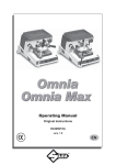
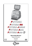
®
OPTIONAL
Universal Loader
D708097ZB
D736245ZB
Automatic feeder
Alimentatore automatico
Automatisches Zuführmagazin
Chargeur automatique
Alimentador automático
Alimentador automático
Automatische toevoereenheid
code: D436250XA - vers.4
(c) 2010 SILCA S.p.A - Vittorio Veneto
All rights reserved. No part of this publication may be reproduced or used in any form or by any means (photocopying,
microfilm or other) without the permission of SILCA S.p.A
Edition: May 2013
Printed in Vittorio Veneto
by SILCA S.p.A.
Via Podgora, 20 (Z.I.)
31029 VITTORIO VENETO (TV)
Italy
Operating manual - English
Automatic Feeder - Unocode 399 PLUS
IMPORTANT NOTE: some of the pictures in this manual show the Unocode 399 PLUS key-cutting machine complete with the following options:
•
Automatic feeder
•
•
Swarf suction unit
Sorter
GENERAL
ATTENTION: the automatic feeder (code D736245ZB) can be run only with a Unocode 399 PLUS keycutting machine which has version 2.1.032 or higher software installed; the version installed on the
key-cutting machine appears on the display when it is turned on.
With the standard machine keys can be cut that normally use side “A” of the base clamp on the
Unocode 399, that is to say, with a maximum cutting depth of no less than 3.9 mm.
Keys with a maximum cutting depth of less than 3.9 mm use side “B” of the standard clamp, and
for these the top and bottom jaws must be replaced with those in the optional set.
Fig. 1
Copyright Silca 2013
3
Automatic Feeder - Unocode 399 PLUS
1
Operating manual - English
FEEDER DESCRIPTION
The feeder is an accessory used to cut flat keys automatically with the Unocode 399 PLUS keycutting machine; keys that require double cuts or have plastic heads cannot be cut.
The feeder holds keys with a thickness of min. 2,1 mm - max. 3,1mm
The machine detects the feeder automatically.
1.1
1.2
Technical data
•
Feeder dimensions (without slide and tray):
depth 390 mm; width 210 mm; height 150 mm
•
Weight
feeder: 6,8 kg - top loader: 0,7 Kg
•
Motion: pneumatic (5 atm min / 6 atm max) with position control sensors and regulation of piston
speed
•
Feeder empty signal sensor
•
Tray full sensor
•
Microprocessor for cycle control
•
Electricity supply: low voltage (24 V)
Accessories provided
Cutter nut
1.3
Main working parts (fig. 2)
C1 D1 G H I1 I2 L L1 L2 K N O O1 P Q R Z -
4
Pin
Top loader
Key unloading unit
Key detection sensor
Feeder unit
Suction unit
Swarf collector (optional swarf suction unit only)
External START/STOP control connector
Tray filling sensor connector (optional sorter only)
Suction unit control connector (swarf suction unit only)
START button
Key tray filling sensor (optional sorter only)
Key tray (optional sorter only)
Key filling stop (optional sorter only)
Feeder serial cable connector
PC connections (serial/USB)
Emergency button
Compressed air pipe
Copyright Silca 2013
Z3 plate
code D939254ZR
Operating manual - English
Automatic Feeder - Unocode 399 PLUS
G
C1
H
N
D1
S2
O
O1
version with SORTER SET
L2
L1
L
version without SORTER SET
I1
P
Q
I2
R
J
L1
L
P
K
Z
Fig. 2
Copyright Silca 2013
5
Automatic Feeder - Unocode 399 PLUS
2
Operating manual - English
INSTALLATION
ATTENTION: turn off the machine before installing the automatic feeder:
Install the feeder in the following way:
1) Turn off the machine and disconnect from the mains;
2) Remove the cutter safety shield (see user’s manual) on the key-cutting
machine (fig. 3).
3) Replace the cutter locking nut (K1) on the machine with the one (K2) provided with the feeder kit.
4) loosen the grub screw (D2) (fig. 5-A) and remove the clamp;
5) install the feeder and take it up against the stop (F1) (fig. 5-B);
6) secure the feeder to the machine by tightening the grub screw (D2);
K2
Fig. 3
7) connect the serial connection cable on the feeder to
the connector (P) situated on the right-hand side of
the key-cutting machine (fig. 2, page 5) and secure by
tightening the two screws (P1) (fig. 7);
8) connect the pneumatic air supply (5 atm min / 6 atm
max) to the coupling;
9) Fix the slide (D1) with the 4 screws (D6) (and relative
nuts) taking care to align the key outlet with the tray
magnet (fig. 6).
K1
K2
Fig. 4
F1
A
D2
B
Fig. 5
D1
D6
D2
P1
P
Fig. 7
6
Copyright Silca 2013
Fig. 6
Operating manual - English
2.1
Automatic Feeder - Unocode 399 PLUS
TOP LOADER
REGULATION AND FITTING:
1) Use a gauge to measure the width of the stem on the key to be cut.
Adjust the slide (C4) position so that the distance (X) is the same as the width of the key stem + 1
mm; secure with the screw (B1).
Fit the loader to the feeder and engage it by moving the slide (C2) and turning the lever (C3) (fig.
9).
Adjust the position of the rear slide (see ) until side “A” of the slide is aligned with the edge of the
feeder plate; secure with the screw (B2).
B1
C4
C4
A
C5
B2
B1
B2
B1
X
Fig. 8
C2
B2
B1
C3
Fig. 9
Copyright Silca 2013
7
Automatic Feeder - Unocode 399 PLUS
Operating manual - English
FILLING THE LOADER:
1) Tip the top part (C5) of the loader so that the keys can be inserted from above (fig. 9) (pay attention
to the position of the key stop).
2) Lower the part (C5) so that the presser can descend and press down the inserted keys (fig. 12).
Note: the slide (C4) is reversible and can be secured to the base of
the loader with the screw (B1) on either the white or yellow reference
point. The choice depends on the thickness of the key to be cut:
place one key on top of another; if measurement “A” (fig. 10) is less
than 3,5 mm secure the slide with the yellow reference point
downwards, if it is over 3,5 mm secure with the white reference point
downwards.
Fig. 10
C5
I
C4
Fig. 11
C5
Fig. 12
8
Copyright Silca 2013
A
Operating manual - English
2.2
Automatic Feeder - Unocode 399 PLUS
REPLACING THE FEEDER GUIDE PLATE
According to the head of the keys to be cut, it may be necessary to replace the feeder guide plate
(optional) (fig. 14).
Proceed as follows:
1) Remove the top loader by turning lever (C3) towards the operator and moving the lever (C2).
1) Loosen the two screws (W2).
2) Pull the feeder guide plate (W1) out through the slot.
3) Slide the new feeder guide plate in and secure in position with the two screws (W2).
W2
W1
Fig. 13
EXAMPLES OF OPTIONAL PLATES
Fig. 14
C2
C3
Fig. 15
Copyright Silca 2013
9
Automatic Feeder - Unocode 399 PLUS
Operating manual - English
3
OPERATING GUIDE
3.1
Gauging Unocode 399 PLUS
F1
From the first display press the MENU key then F1 to enable the function.
Use the “up/down” arrow keys to select the V51 clamp, then press ENTER.
From this display the following adjustments can be made manually.
ATTENTION: adjustments should be made only if necessary and only after automatic gauging.
-
Press START then ENTER.
Press ENTER; the display will show:
Make sure the U01W standard prismatic cutter is fitted.
10
Copyright Silca 2013
Operating manual - English
-
Automatic Feeder - Unocode 399 PLUS
Press ENTER; the display will show:
Z3 plate (D939254ZR)
Z3 test key blank
-
Fit the guide plate for Z3 (D939254ZR)
Fit the Z3 test key blank.
Press START.
When the cycle ends, the display will show:
-
Measure with suitable instruments, then press ENTER:
Values Theoretical
X
Y
-
1000
=
10 mm
450
=
4,5 mm
Enter in the special fields the values for A and B expressed in hundredths of a millimetre.
Note: measurements are accepted if they are the same as or are different by +/- 40 hundredths
of a millimetre from the theoretical values.
A: min. 960 max. 1040
B: min. 410 mx. 490
-
Press ENTER to save the data.
Press START.
-
Press ENTER. The operation is confirmed and the program goes back to the Gauging menu for
the V100 Standard clamp.
Copyright Silca 2013
11
Automatic Feeder - Unocode 399 PLUS
3.2
Operating manual - English
Copy by data card - Unocode 399 PLUS
Follow the instructions on the display. E.g.:
Enter the data card number and press ENTER.
Enter the cuts and number of pieces and press ENTER.
Press START.
-
12
Press STOP to confirm the end of the job.
Press ENTER to continue with other cutting operations.
Copyright Silca 2013
Operating manual - English
3.3
Automatic Feeder - Unocode 399 PLUS
Using the machine with a personal computer
Consult the key-cutting machine user’s manual for the use of a PC.
3.3.1
PC queue - Unocode 399 PLUS
Follow the instructions on the display.
F1
Press F1 to view data relating to the job selected.
-
Press ENTER.
Press F3 to change the type of cycle:
AUTOMATIC Cycle or MANUAL Cycle.
AUTOMATIC Cycle: at the end of a job the keycutting machine automatically goes on to the next
job in the queue and still active (-).
Attention: on the Automatic Cycle place the key
blanks in the feeder in the way required by the
operating sequence.
F3
MANUAL Cycle: at the end of a job the keycutting machine stops. To start the next job the
operator must confirm/choose the operation.
MANUAL Cycle
AUTOMATIC Cycle
Press STOP; the display will show:
-
“+” indicates that the job IS FINISHED.
“-” indicates that the job IS NOT FINISHED.
Copyright Silca 2013
13
Automatic Feeder - Unocode 399 PLUS
3.4
Operating manual - English
Running alarms with feeder - Unocode 399 PLUS
This message appears during the cutting cycle if there are no keys in the feeder.
-
Insert the key blanks and press START.
This message appears if the feeder is blocked and the key cannot be positioned properly.
- Check the position of the key and/or regulation of the loader.
This message appears if a data card not on the machine is selected.
This message appears when the limit switch sensor is unable to read the position of a key.
- Check the position of the key and/or regulation of the loader.
This message appears if the data card does not allow cutting with the feeder (e.g.: double cuts or
using dedicated clamps only).
ONLY WITH OPTIONAL SORTER
O1
This message appears when the key tray is full.
-
14
Unload the cut keys from the tray and move the key holder block
(O1) all the way to the right.
Copyright Silca 2013
Operating manual - English
3.4.1
Automatic Feeder - Unocode 399 PLUS
Test - Unocode 399 PLUS
F2
From the first display press the MENU key, then F2 to enable the function:
Select 3-DIGITAL INLETS and press ENTER. The display will appear:
F4
Press F4, will appear:
ATTENTION: disconnect the compressed air unit from the feeder before performing this test.
-
Input 1: check that the serial connection cable is connected to the key-cutting machine.
Disconnecting and re-connecting the cable will produce transition from OFF to ON.
If the OFF/ON transition is not made, contact Silca After-Sales Service.
-
Input 2: check the key detection sensor (G) on the clamp (fig. 16). To check operation of the
sensor place a key on the plate and move the key advancement slide manually.
If the OFF/ON transition is not made, contact Silca After-Sales Service.
Copyright Silca 2013
15
Automatic Feeder - Unocode 399 PLUS
Operating manual - English
-
Input 3: check the position sensor (C) (fig. 16) for the key slide. To check that the sensor works
properly, move the key slide manually.
If the OFF/ON transition is not made, contact Silca After-Sales Service.
-
Input 4: check the sensor (D) (fig. 16) used to position the slide back.
If there is no OFF/ON transition contact Silca After-Sales Service.
-
Input 5: check the sensor (B) (fig. 16) used to delay slide advancement.
If there is no OFF/ON transition contact Silca After-Sales Service.
-
Input 7: check the feeder guide plate back sensor (F) (fig. 16).
If there is no OFF/ON transition contact Silca After-Sales Service.
-
Input Aux 0: check the external push button (START/STOP).
Connected: ON
Disconnected: OFF
Input Aux 1: check the feeder guide plate sensor (E) forward to eject key.
Input Aux 3: check the tray filling sensor.
Move the key holder block manually towards the sensor.
Tray empty: OFF (block (O1) away from the sensor)
Tray full: ON (block (O1) over the sensor)
-
B
C
E
F
D
G
Fig. 16
Press STOP to go back to the previous menu.
From the initial menu select MAINTENANCE, the display will show:
16
Copyright Silca 2013
Operating manual - English
Automatic Feeder - Unocode 399 PLUS
Select 4-DIGITAL OUTPUTS and press ENTER, the display will show:
The loader outputs are as follows:
Output 1:
This test checks operation of the clamp closure and its solenoid valve (4).
Press START to open and close the clamp and observe on the display transition from OFF to ON.
If transition does not take place contact Silca After-Sales Service.
Output 2:
This test checks operation of the key advancement slide and its solenoid valve (1).
Press START to begin the test; the display will show transition from OFF to ON.
If transition does not take place contact Silca After-Sales Service.
Output 3:
This test checks operation of the key alignment gauge and its solenoid valve (5).
Press START to begin the test; the display will show transition from OFF to ON.
If transition does not take place contact Silca After-Sales Service.
Output 4:
This test checks operation of the key ejection slide and its solenoid valve (3).
Press START to begin the test; the display will show transition from OFF to ON.
If transition does not take place contact Silca After-Sales Service.
Auxiliary output 1:
This test checks operation of the key retraction slide and its solenoid valve (2).
Press START to begin the test; the display will show transition from OFF to ON.
If transition does not take place contact Silca After-Sales Service.
Auxiliary output 4:
This test checks operation of the key positioning piston in the tray.
Press START to begin the test; the display will show transition from OFF to ON.
If transition does not take place contact Silca After-Sales Service.
Swarf suction unit
With the unit connected to the power and air supplies, press START; the display will show transition from OFF to ON and the sound of suction air will be heard.
If transition does not take place contact Silca After-Sales Service.
Press STOP to go back to the previous menu.
Copyright Silca 2013
17
Automatic Feeder - Unocode 399 PLUS
18
Operating manual - English
Copyright Silca 2013
Operating manual - English
Automatic key feeder - Unocode 399 PLUS
Appendix 1 - ELECTRICAL DIAGRAMS
The following pages contain the electrical diagrams for the automatic key feeder for Unocode 399 PLUS
The following pages contain the electrical diagrams for the automatic key feeder.
Copyright Silca 2013
I
IN AUX 3 26
IN AUX 1 25
IN AUX 2 24
OUT 3 23
OUT 2 22
OUT 1 21
OUT 0 20
OUT AUX 0 19
GND 18
GND 17
GND 16
GND 15
IN 8 14
OUT AUX 1 13
+24V 12
+24V 11
+24V 10
+24V 9
IN 7 8
IN 6 7
IN 5 6
IN 4 5
IN 3 4
IN 2 3
IN 1 2
IN 0 1
J4
14
25
Copyright Silca 2013
13 IN AUX 1
25 IN AUX 2
12 OUT 3
24 OUT 2
11 OUT 1
23 OUT 0
10 OUT AUX 0
22 GND
9 GND
21 GND
8 GND
20 IN 8
7 OUT AUX 1
19 +24V
6 +24V
18 +24V
5 +24V
17 IN 7
4 IN6
16 IN 5
3 IN 4
15 IN 3
2 IN 2
14 IN 1
1 IN 0
13 25 SENSORE E
12 ELETTROVALVOLA 3
24 ELETTROVALVOLA 5
11 ELETTROVALVOLA 1
23 ELETTROVALVOLA 4
10 ELETTROVALVOLA 2
22 9 GND
21 8
20 7 19 +24
6 18 5 17 SENSORE F
4 16 SENSORE B
3 SENSORE D
15 SENSORE C
2 SENSORE G
14
1 8
1
8 - ELETTROVALVOLA 1
15 SENSORE F
7 ELETTROVALVOLA 3
14 SENSORE C
6 ELETTROVALVOLA 4
13 SENSORE E
5 ELETTROVALVOLA 5
12 SENSORE B
4 ELETTROVALVOLA 2
11 SENSORE D
3 GND 3
10
2 +24
9 GND
1 - SENSORE G
ALIMENTATORE AUTOMATICO
AUTOMATIC FEEDER
ALIMENTATEUR AUTOMATIQUE
ALIMENTADOR.. AUTOMATICO
AUTOMATISCHE ZUFUHRER
15
9
14
1
1
13
8
15
7
14
6
13
5
12
4
11
3
10
2
9
1
Operating manual - English
Automatic key feeder - Unocode 399 PLUS
25
13
III
IV
AIR INLET
at 5/6 atm
MARCA CAVO
14
8
5
Copyright Silca 2013
5
4
1
3
2
2
KEY GAUGE
14
3
4
1
5
4
1
CLAMPS
3
2
SUB-BASE
14
7
3
sensori
5
4
1
4
3
2
UNLOADING SLIDE
14
PNEUMATIC DIAGRAM FOR UNOCODE 399 PLUS LOADER
1
5
4
1
6
3
2
2
sensori
5
12
LOADING SLIDE
Automatic key feeder - Unocode 399 PLUS
Operating manual - English
PNEUMATIC SYSTEM DIAGRAMS