1
Software: Critical Motion Control System Component
Considerations Before You Buy
Click on Slide to start presentation
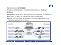
Nanopositioning System:
Precision Mechanics + Control Electronics + Software
Software
Enables the access to the full performance of the motion control system
Can make the life of the programmer easy or a nightmare
Should be independent of mechanics / controller hardware to allow
hassle free upgrades in the future
Previous Slide
Previous Chapter
Overview
Next Chapter
Next Slide
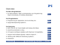
Overview
For Non-Programmers
1. PI Host Software: Start-up & Operation w/o Programming…
Macro Commands, for Simple Automation
More…
For Programmers:
2. Programming an Application can be As Easy As…
More…
3. Supported Operating Systems…
More…
For Everyone
4. GCS: One for all: Runs Digital and Analog Interfaces
More…
5. Good Documentation is Key…
More…
6. Firmware & Software Updates with Maximum Compatibility…
More…
7. Support and Software Quality: What to Expect? …
More…
8. Working with Different Positioning Systems…
More…
9. Disclaimer
More…
Previous Slide
Previous Chapter
Finish Presentation
Next Chapter
Next Slide
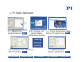
1. PI Host Software
Good Software ….
… guides the user through the installation
… includes quick start programs and simple system tests
… offers Online Help
Plus from PI:
• Macro Commands Allow Simple Automation Tasks
• In addition to terminal support and ASCII protocol ....
Previous Slide
Previous Chapter
Overview
Next Chapter
Next Slide
1. PI Host Software
1.1. Observe the
System Behavior
More…
Full CD Setup with 1.2. Simple Automation Tasks
Customizable
Without Programming More…
Installation Routine
Getting
Started
Quickly
1.4. Software-based
System optimization
1.3. Fast Basic And Advanced
Wave Definition More…
Previous Slide
Previous Chapter
Overview
Next Chapter
More…
Next Slide
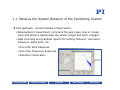
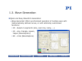
1.1. Observe the System Behavior of the Positioning System
First approach - System Behavior Observation:
• Nanocapture‘s Visual Panel: command the axis (open-loop or closedloop) and observe dynamically the sensor output and piezo voltages.
• Data recording and graphical reports for settling behavior, resonance
frequency, Bode plots, etc. :
One-Click Step Response
One-Click Frequency Response
Waveform Generation
Previous Slide
Previous Chapter
Overview
Next Chapter
Next Slide
1.2. Simple Automation Tasks with PIMikroMove
Example: How to save the current position and return later
External link, flash movie running in browser window:
with one single click
More…
Example: How to store different wave definitions and recall
later with one single click External link, flash movie running in browser window:
More…
Previous Slide
Previous Chapter
Overview
Next Chapter
Next Slide
1.3. Wave Generation
Quick and Easy Waveform Generation
• Wave Generator offers synchronized operation of multiple axes with
mathematically defined curves, or with arbitrarily customized
functions:
1D - based on segments (sine, scan line, ramp, ...)
1D - sine, triangle, square,
trapez (NanoCapture)
2D - circle (NanoCapture)
Previous Slide
Previous Chapter
Overview
Next Chapter
Next Slide
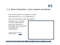
1.3. Wave Generation: more complex waveforms
• More specific waveform configuration possible.
• Import data files (e.g. .csv) (PIMikroMove)
• Save and load definition files (NanoCapture)
• Simulation w/o connected
controller (NanoCapture)
• Store wave definitions in
HostMacros and execute them
by a single click
(PIMikroMove)
External link, flash movie running
in browser window:
More…
Previous Slide
Previous Chapter
Overview
Next Chapter
Next Slide
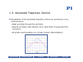
1.3. Advanced Trajectory Control
Visualization of the generated trajectory without an oscilloscop or any
external device
• Data recording through the controller.
• Reports of Target, Real Position, Error (and others if supported from
controller).
• 2D graph report possible (i.e. circular motion) (NanoCapture)
Previous Slide
Previous Chapter
Overview
Next Chapter
Next Slide
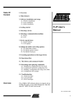
1.3. Advanced Trajectory Control
Tracking Errors:
• Controller option DDL reduces errors considerably
• This feature and its optimization is fully integrated in the software.
• Example curves (target, real position and error of a sine wave):
DDL
Previous Slide
Previous Chapter
Overview
Next Chapter
Next Slide
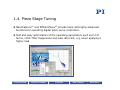
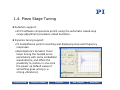
1.4. Piezo Stage Tuning
NanoCapture™ and PIMikroMove™ provide basic and highly advanced
functions for operating digital piezo servo-controllers.
Fast and easy optimization of the operating parameters such as P-I-D
terms, notch filter frequencies and slew rate limit, e.g. when applying a
higher load
Previous Slide
Previous Chapter
Overview
Next Chapter
Next Slide
1.4. Piezo Stage Tuning
AutoZero support:
• All PI software components permit using the automatic closed-loop
range adjustment procedure called AutoZero.
Dynamic tuning support:
• PI hostsoftware permit recording and displaying step and frequency
responses.
• NanoCapture‘s Dynamic Tuner
helps tuning the needed servo
parameters with some embedded
automatisms, and offers the
possibility to restore in one-click
the power up default values if
something goes wrong (i.e.
strong vibrations).
Previous Slide
Previous Chapter
Overview
Next Chapter
Next Slide
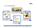
2. For Programmers
2.1. Full LabVIEW Support for
LabVIEW Programmers More…
2.3. Full MatLab Support
for MatLab Users More…
2.2. Full Support for Text
Based Programmers More…
2.4. Sample Code for All
Programmers More…
Previous Slide
Previous Chapter
Overview
Next Chapter
Next Slide
2.1. GCS LabVIEW Driver Libraries
Plus from PI: Not only sample VIs but: Full GCS LabVIEW driver set
Supports all PI controllers, independent of
positioner hardware and controller interface
(USB, TCP/IP, RS-232 and even analog!)
One software driver can run piezo, DC motor,
stepper, hybrid and hexapod controllers
together in one application.
Quick and easy setup with special
Configuration Setup VI (executed only once):
• Gathers all necessary system information for LabVIEW, including:
Communication parameters
Connected controller(s)
Types & configurations of the connected stages/axes
• Performs all necessary initialization steps.
Previous Slide
Previous Chapter
Overview
Next Chapter
Next Slide
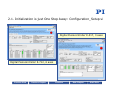
2.1. Initialization is just One Step Away: Configuration_Setup.vi
Digital Piezocontroller E-517, 3 axes
Digital Piezocontroller E-712, 6 axes
Previous Slide
Previous Chapter
Overview
Next Chapter
Next Slide
2.1. GCS LabVIEW Driver Libraries
GCS LabVIEW driver set consists of:
High Level VIs
Low Level VIs, consisting of Libraries (LLBs):
PI
POS?
» Communication.llb for all supported
interfaces including analog control w/ HyperBit
» Support.llb (programming support for common tasks)
» Different command LLBs supporting full controller functionality
• Unified icon and user interface (connector panel)
• All open source! (except Configuration_Setup.vis)
• including GUI programs like scanning routines, graphical
representation, wave generator samples, debugging routine,
merge tool, terminal application, configuration software etc.
• with Online help window for each VI
Previous Slide
Previous Chapter
Overview
Next Chapter
Next Slide
2.1. Special Routines Available in LabVIEW (Excerpt)
Previous Slide
Previous Chapter
Overview
Next Chapter
Next Slide
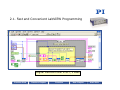
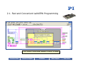
2.1. Fast and Convenient LabVIEW Programming
Digital Piezocontroller E-712, 6 axes
Previous Slide
Previous Chapter
Overview
Next Chapter
Next Slide
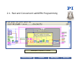
2.1. Fast and Convenient LabVIEW Programming
Digital Piezocontroller E-517, 3 axes
Previous Slide
Previous Chapter
Overview
Next Chapter
Next Slide
2.1. Fast and Convenient LabVIEW Programming
PCI Motor Controller Board C-843, 4 axes
Previous Slide
Previous Chapter
Overview
Next Chapter
Next Slide
2.1. Fast and Convenient LabVIEW Programming
z
Hexapod System M-850
Previous Chapter
Overview
Next Chapter
Next Slide
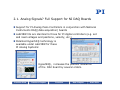
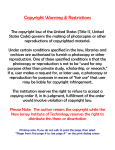
2.1. Analog Signals? Full Support for NI DAQ Boards
Support for PI Analog Piezo Controllers in conjunction with National
Instruments DAQ (data acquisition) boards
LabVIEW VIs are identical to those for PI digital controllers (e.g. set
and read voltages and positions, velocity, etc.)
Patented Hyperbit® technology is
available under LabVIEW for these
PI Analog Systems:
•
•
Previous Slide
HyperBit®, increases the position resolution
of the DAC board by several orders.
Previous Chapter
Overview
Next Chapter
Next Slide
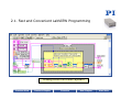
2.1. Fast and Convenient LabVIEW Programming
Analog Piezo Controller System
Previous Slide
Previous Chapter
Overview
Next Chapter
Next Slide
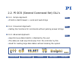
2.2. PI GCS (General Command Set) DLL‘s
2.2.1. Simple Approach:
More…
• PI GCS is ASCII based -> send and read strings
2.2.2. Convenient Approach:
More…
• Calling DLL functions for commands without parsing answer strings
2.2.3. Advanced Approach:
More…
• Asynchronous data transfer, initialized by the user
• The data are read asynchronously from the controller by DLL
• Good for reading large data tables without blocking the system
Previous Slide
Previous Chapter
Overview
Next Chapter
Next Slide
2.2.1. PI GCS is ASCII based -> sending and reading strings
int main ()
{
int iId;
int iCommPort = 1;
int iBaudRate = 115200;
char szAnswer[1024];
// Connect the controller using e.g. RS232.
iId = E7XX_ConnectRs232(iCommPort, iBaudRate);
// Send the command “POS?” to query the position of axis 1 and 2.
E7XX_GcsCommand(iId, „POS? 1 2“);
// Read the answer of the controller.
E7XX_GcsGetAnswer(iId, szAnswer, 1024);
printf(„%s“, szAnswer);
// 1 = 50.3
// 2 = 21.5
Good to display the
answer such as in a
terminal program
Uncomfortable for
programming sequences
because each answer
string has to be parsed.
// Parsing the answer string ‘szAnswer‘.
…
// Close the connection to the controller.
E7XX_CloseConnection(iId);
}
Previous Slide
Previous Chapter
Overview
Next Chapter
Next Slide
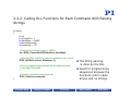
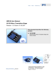
2.2.2. Calling DLL Functions for Each Command W/O Parsing
Strings
int main()
{
int iId;
int iCommPort = 1;
int iBaudRate = 115200;
double dPositions[2];
char szAxes[] = „1 2“;
// Connect the controller using e.g. RS232.
iId = E7XX_ConnectRs232(iCommPort, iBaudRate);
// Send the E7XX_qPOS() to querry the position of axis 1 and 2.
E7XX_qPOS(iId, szAxes, dPositions, 2);
// do your programming sequences with the positions stored
// in the array ‘dPositions’.
…
}
// Close the connection to the controller.
E7XX_CloseConnection(iId);
Previous Slide
Previous Chapter
Overview
The string parsing
is done by the DLL
Good for programming
sequences because the
functions return value
arrays and no strings.
Next Chapter
Next Slide
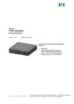
2.2.3. Asynchronous Data Transfer
int main ()
{
int iId, iIndex, iCommPort = 1, iBaudRate = 115200;
int iRecordChannelIds[] = {1, 2, 3};
double* dDataTable;
char szHeader[1024];
// Connect the controller using e.g. RS232.
iId = E7XX_ConnectRs232(iCommPort, iBaudRate);
// Initialize data transfer of 10000 values for the
// record channels 1, 2 and 3.
E7XX_qDRR(iId, iRecordCannelIds, 3, 1, 10000, &dDataTable,
szHeader, 1024 );
// Go on with your specific program sequences.
…
// Find our how many values are already read form the controller,
// where ‘iIndex’ is the current index in the data Table ‘dDataTable’.
iIndex = E7XX_GetAsyncBufferIndex(iId);
…
}
Previous Chapter
Allows reading large
data tables without
blocking the
application
Get data from the
DLL when needed
// Close the connection to the controller.
E7XX_CloseConnection(iId);
Previous Slide
Data are read and
stored
asynchronously by
DLL threads
Overview
Next Chapter
Next Slide
2.3. PI is Connections Partner of The Mathworks™
Previous Slide
Previous Chapter
Overview
Next Chapter
Next Slide
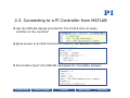
2.3. Connecting to a PI Controller from MATLAB
Use the MATLAB classes provided for the PI GCS DLLs to easily
interface to the controller
Quick access to all GCS functions of the DLL, like absolute motion
Direct data import into MATLAB workspace for immediate analysis
Previous Slide
Previous Chapter
Overview
Next Chapter
Next Slide
2.3. Motion Performance Data Recorded by Controller
Previous Slide
Previous Chapter
Overview
Next Chapter
Next Slide
2.3. Interactive Use of the Controller Class
You can use the Controller class in the Command window interactively
Use the TAB-Key to see functions available for a controller:
Previous Slide
Previous Chapter
Overview
Next Chapter
Next Slide
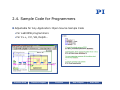
2.4. Sample Code for Programmers
Adjustable for Any Application: Open Source Sample Code
• For LabVIEW programmers
• For C++, C#, VB, Delphi…
Previous Slide
Previous Chapter
Overview
Next Chapter
Next Slide
3. Supported Operating Systems
Microsoft Windows:
Windows 2000, Windows XP, Windows VISTA, Windows 7
Plus from PI: Linux support, no ActiveX based software
• Linux libraries
• Linux LabVIEW drivers
Plus from PI: 64 bit components:
• 64 bit components for Microsoft VISTA 64bit.
Previous Slide
Previous Chapter
Overview
Next Chapter
Next Slide
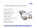
4. GCS: What does it mean for the User?
PI’s General Command Set (GCS) was designed for maximum
compatiblity of all motion systems and hassle free updates
Universal Command Set simplifies commissioning and programming
GCS operation is independent of the controller or drive principle used.
Different positioning systems can be run together from one software,
or new systems can be added with minimum programming effort.
Previous Slide
Previous Chapter
Overview
Next Chapter
Next Slide
4. GCS: What does it mean for the User?
Unified command syntax
Unified error codes
Unified parameter numbers
ONE LabVIEW driver set
Unified DLL objects
ONE host software
PIStages.dat parameter data base
Unified manuals
Unified setup procedure
Complete system tests
Previous Slide
Previous Chapter
Overview
Next Chapter
Next Slide
4. GCS is a Time Saver for Programmers
With GCS the development of custom application programs is simplified
and less prone to errors, because the commands for all supported
devices are identical in syntax and function
Through the use of the GCS command set with its convenient functions,
the orientation phase and application development process is
significantly accelerated.
Previous Slide
Previous Chapter
Overview
Next Chapter
Next Slide
5. Good Documentation is the Key
Comprehensive manuals for quick start-up, and detailed answers for
professional programmers
• Hardware User Manual
• Manuals for all software components
Full online-help available for
• PI Host Software
• PI GCS LabVIEW Driver Set
Free Manual Downloads, Free Software
Downloads for PI Customers
External link, will open
browser window:
Previous Slide
More…
Previous Chapter
Overview
Next Chapter
Next Slide
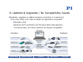
6. Updates & Upgrades / No Compatibility Issues
Updates, upgrades or added hardware (controller or mechanics):
How much effort will it take to adapt my application programs?
• Basically none!
• Because all PI controllers use the same GCS code (General
Command Set), all motion systems are always compatible.
Previous Slide
Previous Chapter
Overview
Next Chapter
Next Slide
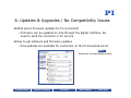
6. Updates & Upgrades / No Compatibility Issues
What about firmware updates for PI controllers?
• Firmware can be updated on-site through the digital interface. No
need to send the controller in for service.
How to get software and firmware updates
• Free updates are available for customers on the PI download server
More…
External link, will open browser window
Previous Slide
Previous Chapter
Overview
Next Chapter
Next Slide
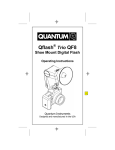
7. Application Support: Free of Charge
What about help with setting up the system, troubleshooting or
application programming?
• PI engineers help you with your application. Local support is available
in most countries as well as quick factory direct support.
PI Europe, USA, China, Japan
What about Remote Service?
• A number of PI controllers come with
TCP/IP interfaces and could even be
serviced / tuned through the internet.
Internet
PI customers
Previous Slide
Previous Chapter
Overview
Next Chapter
Next Slide
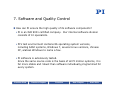
7. Software and Quality Control
How can PI ensure the high quality of its software components?
• PI is an ISO 9001 certified company. Our internal software division
consists of 10 specialists.
• PI‘s test environment contains 86 operating system versions,
including 64bit systems, Windows 7, several Linux versions, chinese
XP, arabian Windows to name a few.
• PI software is extensively tested.
Since the same source code is the basis of all PI motion systems, it is
far more stable and robust than software individually programmed for
every system.
Previous Slide
Previous Chapter
Overview
Next Chapter
Next Slide
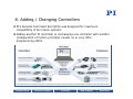
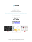
8. Adding / Changing Stages with a Controller
• Configuration is as easy as
picking a new stage from a list.
• No need to find parameters
through trial & error. No
manual typing of parameters.
• Third party stages can be added &
used as if they were PI stages.
• ID chip is available for piezo flexure positioning systems. These come
preconfigured and send all parameters to the controller once connected.
• In addition servo parameters can be changed online with guided
tuning. More…
Previous Slide
Previous Chapter
Overview
Next Chapter
Next Slide
8. Adding / Changing Controllers
PI‘s General Command Set (GCS) was designed for maximum
compatiblity of all motion systems
Adding another PI controller or exchanging one controller with another
(independent of motion principle) causes no or very little
programming effort.
Previous Slide
Previous Chapter
Overview
Next Chapter
Next Slide
9. Disclaimer
Physik Instrumente (PI) GmbH & Co. KG
Auf der Römerstrasse 1
D-76228 Karlsruhe/Palmbach
Tel.: (0721) 4846-0
Fax: (0721) 4846-100
E-Mail: [email protected]
Internet: www.pi.ws
The following designations are protected company names or registered
trademarks of third parties:
Microsoft, Windows, LabView
PI Software Overview V1.0.0
Previous Slide
Previous Chapter
Overview
Next Chapter
Next Slide