1
4-
Portable Base Assembly 6
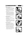
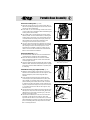
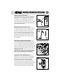
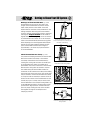
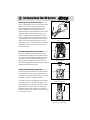
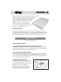
Attach the Locking Tabs (Fig. 6A&B)
1. Align the center-hole of each of the Locking Tabs to
the corresponding mounting hole on the rear vertical
surface of the Portable Base.
2. Insert a #6 x 3/8” screw through center-hole of each
of the Locking Tabs and tighten while still allowing the
Locking Tabs to move freely.
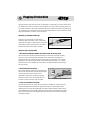
3. The smaller pad of the Premium Face Clamp will be
held in position on the Portable Base by rotating the
Locking Tabs so that they cover the outside surface
of the Premium Face Clamp pad. Proper position of
the Premium Face Clamp will be outlined in the
“Getting to Know Your K3 System” section.
4. You may notice that there are raised ribs on the rear
outside surface of the K3 Portable Base surrounding
the openings used for wood chip ejection. These
raised ribs are provided so that any clamp may be
used to secure the K3 Portable Base and Drill Guide
Block to the material to be drilled.
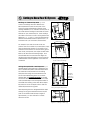
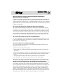
Attach the Index Pin (Fig. 6C)
1. Thread the Brass Index Pin into the threaded insert
contained in the upright of the Portable Base.
2. Back off the Brass Index Pin so that the rounded
point of the Brass Index Pin is flush with the inside
of the upright surface.
3. The Brass Index Pin will be seated fully when the Drill
Guide has been inserted in the opening of the upright
and used to hold the Drill Guide Block in position prior
to clamping.
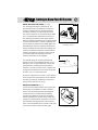
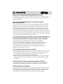
Assemble the Kreg Jig® Support/Stop (Fig. 6D)
1. Slide the center tongue of the Support/Stop Arm
between the outside extensions of the Support/Stop
Base and align the pivot hole through all three
surfaces.
2. Insert the Pivot Pin through one outside surface
of the Support/Stop Base and either tap into place
with a mallet or a hammer and a block of wood to
prevent marring the end of the Pivot Pin. Continue
to advance the Pivot Pin until it is fully seated in the
Support/Stop Base and Support/Stop Arm. Push the
1/4”-20 Hex Nut into the side of the Support/Stop
Arm hex recess.
3. Thread the Nylon Stop Bolt from either side through
the Support/Stop Arm into the Hex Nut. Which side
will depend on which side of the Kreg Jig® that the
Support/Stop will be used.
4. Thread the Knurled Nylon Lock Nut onto the Nylon
Stop Bolt on the side of the Support/Stop Arm
opposite the Hex Nut. It may be necessary to thread
the Knurled Nylon Lock Nut onto the Nylon Stop Bolt
prior to threading the Nylon Stop Bolt into the Hex
Nut in some applications.
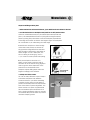
Fig. 6A
Locking Tabs on Portable Base.
Fig. 6B
Locking Tabs holding the Premium
Face Clamp in position.
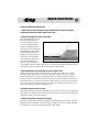
Fig. 6C
How to insert the Brass Index Pin.
Hex Recess
Knurled
Nylon
Lock
Nut
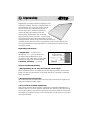
Fig. 6D
Nylon Bolt
Arm
Hex Nut
Base
Pivot Pin
Support/Stop assembly diagram