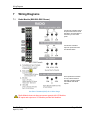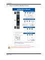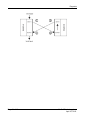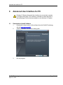
1
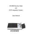
Wireless I/O System April 20, 2015 USER GUIDE User Guide Your Feedback Please We always want you to feel that you made the right decision to use our products. If you have suggestions, comments, compliments or complaints about our products, documentation, or support, please write or call us. How to Contact Us ProSoft Technology 5201 Truxtun Ave, 3rd Floor Bakersfield, CA 93309 +1 (661) 716-5100 +1 (661) 716-5101 (Fax) http://www.prosoft-technology.com [email protected] Copyright © 2015 ProSoft Technology, Inc. All rights reserved. Wireless I/O System User Guide April 20, 2015 ProSoft Technology® Product Documentation In an effort to conserve paper, ProSoft Technology no longer includes printed manuals with our product shipments. User Manuals, Datasheets, Sample Ladder Files, and Configuration Files are provided on the ® enclosed DVD in Adobe Acrobat Reader file format (.PDFs). These product documentation files may also be freely downloaded from our web site: www.prosoft-technology.com ProSoft Technology, Inc. April 20, 2015 Page 3 of 48 Wireless I/O System User Manual Page 4 of 48 ProSoft Technology, Inc. April 20, 2015 Wireless I/O System User Manual Contents Your Feedback Please ........................................................................................................................ 3 How to Contact Us .............................................................................................................................. 3 ® ProSoft Technology Product Documentation .................................................................................... 3 1 Preface 1.1 2 7 Compliances .............................................................................................................. 8 System Overview 2.1 2.2 2.3 2.4 2.5 2.6 2.7 3 Highlights ................................................................................................................. 11 Ease of Use ............................................................................................................. 12 Faster Deployment and Less Maintenance............................................................. 12 Faster, Smarter, Secure, Failsafe ........................................................................... 12 Customer, Scalable I/O Expansion ......................................................................... 12 Advanced Features ................................................................................................. 13 Hardware ................................................................................................................. 14 Specifications 3.1 3.2 3.3 3.4 3.5 3.6 3.7 4 11 15 Hardware and System ............................................................................................. 15 Safety and Compliance ........................................................................................... 15 Radio Module .......................................................................................................... 16 Digital I/O Module .................................................................................................... 17 4-20 mA I/O Module ................................................................................................ 17 0-10 V I/O Module ................................................................................................... 18 Ordering Information ............................................................................................... 18 Installation 4.1 4.2 4.3 19 Outdoor Enclosure Installation ................................................................................ 19 Wireless I/O System Assembly (attach from left to right) ........................................ 20 Detaching Components from the DataRail .............................................................. 24 5 Radio Setup 25 6 Signal Chain Diagram 27 7 Wiring Diagrams 29 7.1 7.2 7.3 7.4 8 Radio Module (BM-0900-RM1 Shown) ................................................................... 29 Digital Module (BM-D100-144 Shown) .................................................................... 30 Analog 4-20 mA Module (BM-A420-122 Shown) .................................................... 31 Analog 0-10 V Module (BM-A010-122 Shown) ....................................................... 32 Diagnostics 8.1 ProSoft Technology, Inc. April 20, 2015 33 Radio Module .......................................................................................................... 33 Page 5 of 48 Wireless I/O System User Manual 9 Advanced User Interface for PC 9.1 9.2 9.3 9.4 9.5 9.6 9.7 9.8 35 Download and Install Software ............................................................................... 35 Connect USB to Mini USB Cable (Included with Radio Kit) ................................... 36 View of Graphic User Interface (GUI) ..................................................................... 37 Main Window Guide ................................................................................................ 38 Additional Diagnostics ............................................................................................ 39 Digital Module Window Guide ................................................................................. 40 4-20 mA Module Window Guide ............................................................................. 41 0-10 V Module Window Guide ................................................................................ 42 10 Frequently Asked Questions 43 11 Support, Service & Warranty 47 11.1 Page 6 of 48 Warranty Information .............................................................................................. 48 ProSoft Technology, Inc. April 20, 2015 Preface 1 Preface Thank you for choosing the Wireless I/O System - an intelligent, bi-directional wireless I/O mirroring solution that is ideal for replacing hardwire and conduit or for implementing it into new infrastructures. The Wireless I/O System requires no software or programming and is extremely easy to install and use. It’s the easiest way from point A to point B, and back. This document is designed to guide you through setting up the system by familiarizing you with the hardware, installation, wiring, and overall system management. This guide also provides how to use the Wireless I/O System’s Advanced User Interface. If you have any questions about this product, please call or email: ProSoft Technology 5201 Truxtun Ave, 3rd Floor Bakersfield, CA 93309 +1 (661) 716-5100 +1 (661) 716-5101 (Fax) http://www.prosoft-technology.com [email protected] Warning: Ensure the installation of the system meets applicable state and national electrical code requirements. The installation of the system should only be performed by a qualified installer or a factory representative. Warning: To prevent ignition of flammable or combustible atmospheres, disconnect power before servicing. Warning: Power must be disconnected or turned off prior to attaching or removing any I/O Modules from the system – failure to comply may cause damage to the I/O Module(s). ProSoft Technology, Inc. April 21, 2015 Page 7 of 48 Preface 1.1 Compliances This device MUST be professionally installed by a factory representative or a trained authorized technician. Changes or modifications not expressly approved by the manufacturer may void the user’s authority to operate the equipment. This device complies with Part 15 of the FCC Rules. Operation is subject to the following two conditions: 1) this device may not cause harmful interference, and 2) this device must accept any interference received, including interference that may cause undesired operation. To reduce potential radio interference to other users, install and use only the antenna supplied by the manufacturer to ensure successful communications. FCC RF Exposure To comply with FCC RF exposure compliance requirements, a separation distance of at least 20 cm must be maintained between the antenna of this device and all persons. FCC Interfere This equipment has been tested and found to comply with the limits for a class B digital device, pursuant to Part 15 of the FCC Rules. These limits are designed to provide reasonable protection against harmful interference in a residential installation. This equipment generates, uses and can radiate radio frequency energy and if not installed and used in accordance with the instructions, may cause harmful communications to radio communications. However, there is no guarantee that interference will not occur in a particular installation. If this equipment does cause harmful interference to radio or television reception, which can be determined by turning the equipment off and on, the user is encouraged to try to correct the interference by one of the following measures: Page 8 of 48 ProSoft Technology, Inc. April 21, 2015 Preface Reorient or relocate the antenna. Increase the separation between the equipment and receiver. Consult the manufacturer for technical help. This equipment has been certified to comply with the limits for a class B computing device, pursuant to FCC Rules. In order to maintain compliance with FCC regulations, shielded cables must be used with this equipment. Operation with non-approved equipment or use of unshielded cables is likely to result in interference to radio and television reception. The user is cautioned that changes or modifications made to the equipment without the approval of the manufacturer could void the user’s authority to operate this equipment. ProSoft Technology, Inc. April 21, 2015 Page 9 of 48 System Overview 2 System Overview 2.1 Highlights Wireless hardwire replicator / rapid reliable wireless connectivity. Save money and time: Wireless I/O System eliminates trenching and running conduit / deploys in minutes. Easy to use: no software configuration needed. Easy to install: mounts onto a 35 mm DIN rail without any tools. Flexible: place inputs and output on both ends of radio. Customize I/O using Digital, 0-10 V, and/or 4-20 mA options. Isolated: each Module provides field isolated inputs and outputs. 24-bit high-resolution Analog inputs. Fast response time: 1 second default / turbo-mode up to 100 ms depending on number of connection I/O Modules. RF and I/O fail detection: NPN outputs on Radio Modules. Secure: factory paired, secure Radio System (128-bit AES) keeps network protected Less wire clutter: single power termination per station. Wiring label on each device for quick reference. Color-coded labels for easy device identification. FailSafe: user can defines how outputs are failed over when RF or I/O communication is ever lost. FailSafe output modes: Digital: On, off, last known value (default) Analog: Any value on scale (Advanced UI required), last known value (default) Provides manual FailSafe override function via dry contact input on Radio Module. Wireless I/O System can support multiple I/O Modules. System can support up to sixteen (16) Digital Modules max. System can support up to eight (8) 0-10 V Modules max. System can support up to five (5) 4-20 mA Modules max. Warning: When adding more than five (5) I/O Modules and creating different I/O Module combination, please determine maximum allowable I/O Module combination per system by utilizing the power budget calculator. See http://psft.com/A5D ProSoft Technology, Inc. April 21, 2015 Page 11 of 48 System Overview 2.2 Ease of Use When faced with having to replace an existing hardwired system or installing new infrastructure, the Wireless I/O System is the fastest, easiest, and most economical methods for wirelessly duplicating discrete, 4-20mA, or 0-10V signal wire. All I/O Modules feature isolated inputs and outputs. The Wireless I/O System requires no configuration or software and is extremely quick and easy to install. The Wireless I/O System mounts to 35 mm DIN rail. Then, you just need a screwdriver and a wire stripper to terminate input, outputs, and power. 2.3 Faster Deployment and Less Maintenance Significant amount of time and money can be saved by avoiding permitting and trenching to run wires. Because deployment time is so rapid using the Wireless I/O System, you can even use it as an emergency backup system when a hardwired system is down for repair or maintenance. And by removing the hardwire run, it also eliminates the potential cost for future wire failure replacement and maintenance due to natural disasters such as lightning. Troubleshooting also become much easier and quicker with the Wireless I/O System since there are less points of failure than a hardwire system. 2.4 Faster, Smarter, Secure, Failsafe In the Wireless I/O System, the Radio Modules control and power everything. They manage all signal traffic and provide critical alarms and diagnostics when either RF link failure or I/O mismatch is detected and trigger NPN digital outputs for notification. At the same time, the Radio Module overrides all outputs into the user’s predetermined FailSafe output states on each I/O Module. Each output is independently controlled. It also provides the ability to locally force outputs when setting up the system without needing a real signal source. The paired Radio Modules communicate at a default response time of 1 second. The Radio Modules can be put to Turbo Tx mode and the response time varies with the number of connected I/O Modules, up to 100 ms. The Radio Modules utilize AES encryption for securely delivering data and are offered in 900 MHz or 2.4 GHz (license-free ISM), in both domestic (US) and international versions. Antennas and antenna cables are sold separately so that you can select the appropriate antenna and cable lengths to fit your application. 2.5 Customer, Scalable I/O Expansion The Radio Kit is the foundation of the Wireless I/O System that allows you to build your custom I/O solution. The two (2) factory-paired Radio Modules are packaged in the Wireless I/O Radio Kit. The Kit also includes all the mounting hardware so you simply need to add the I/O Modules of your choice. Up to five (5) pairs of I/O Modules of any kind can be operated using the Radio Kit. If additional I/O Modules are needed for expansion, the Wireless I/O System can support many more pairs of I/O Modules using a longer DataRail. Page 12 of 48 ProSoft Technology, Inc. April 21, 2015 System Overview 2.6 Advanced Features The Wireless I/O System also offers an Advanced User Interface for PC. By connecting the PC to the Radio Module’s mini-USB port, you can check vital system health such as RSSI (Received Signal Strength Indication), view input/output status, adjust transmit power level, and adjust RF timeout interval. You can also locally force local outputs, set FailSafe settings individually for analog outputs. Digital outputs are set using DIP switches that are physically on the device. ProSoft Technology, Inc. April 21, 2015 Page 13 of 48 System Overview 2.7 Hardware 1. 2. 3. 4. 5. 6. 7. Page 14 of 48 Radio Module: BM-0900-RM1 (US), BM-0915-RM1 (Int), BM-2400-RM1 (US), BM-2410-RM1 (Int) Digital Module: BM-D100-144 (US); BM-D100-244 (International) 4-20 mA Analog Module: BM-A420-122 (US); BM-A420-122 (International) 0-10 V Analog Module: BM-A010-122 (US); BM-A010-122 (International) DataRail attaches onto 35 mm x 7.5 mm DIN rail (Standard length included in Radio Kit can support 1 Radio + 5 I/O Modules) End Terminal Bracket for securing DataRail and Modules to DIN Rail DataRail Cover for protecting empty DataRail slots ProSoft Technology, Inc. April 21, 2015 Specifications 3 Specifications 3.1 Hardware and System HARDWARE & SYSTEM Unique System Features Bi-Directional Wireless Communication System No Software or Programming Required Maximum Network Capacity* System can support up to sixteen (16) Digital Modules max System can support up to eight (8) 0-10 V Modules max System can support up to five (5) 4-20 mA Modules max When adding more than five (5) I/O Modules and creating different I/O Module combination, please determine maximum allowable I/O Module combination per system by utilizing the power budget calculator. Use Power Budget Calculator http://psft.com/A5D DIN Rail Mounting Compatibility 35 mm x 7.5 mm DIN Rail DataRail™ (Included with Radio Kit) 6.1" / 156 mm - Supports Up Five (5) I/O Modules, Other Lengths Also Available Module Slave ID Selection 16-Position Rotary Switch DataRail Mounting Hardware 4-Claw Attachment to 35 mm DIN Rail with End Terminal Bracket Built-In Mounting Hardware Spring-Loaded Clip-On System Wire Gauge Solid / Stranded (AWG) 28-12 Gauge Wire Rating UL: 300 V RMS, 80 °C and 300 V, 105 °C CSA: 300 V RMS, 105 °C Warranty 3.2 2-Year Limited Safety and Compliance SAFETY & COMPLIANCE RADIO Operational Temperature -40 °C to 85 °C / -40 °F to 185 °F Ambient Temperature -20 °C to 85 °C / -4 °F to 185 °F Humidity 0 to 99 %, Non-condensing Degree of Protection / Housing Type IP20 / Plastic Hazardous Locations Classifications Class I; Division 2 (Zone 2), Pending RF Emissions FCC Part 15/IC ProSoft Technology, Inc. April 21, 2015 Page 15 of 48 Specifications 3.3 Radio Module RADIO MODULE 900 MHz or 2.4 GHz Frequency 902-928 MHz or 2.4 GHz License-Free ISM Band Antenna Connector Type SMA (Female Connector) Default Transmit Speed / Update 1 Second Turbo Tx Speed Based on 1=100 ms, 2-3=200 ms, 4=250 ms, 5-6=333 ms, # of I/O Modules 7-11=500 ms, 12-16=1 second Outdoor / Line of Sight Max Range 900 MHz: 4 Miles (6.4 Km) / 2.4 GHz: 1 Mile (1.6 Km) / (900MHz@250mW/2.4GHz@63mW) 2.4 GHz International: 2500 ft (750 m) Indoor / Urban Max Range 900 MHz: 1000 ft (305 m) / 2.4 GHz: 300 ft (90 m) / (900MHz@250mW/2.4GHz@63mW) 2.4 GHz International: 200 ft (60 m) Maximum Transmit Power 900 MHz: 24 dBm (250 mW) / 2.4 GHz: 18 dBm (63 mW) / (Adjustable by Software) 2.4 GHz International: 10 dBm (10 mW) Receiver Sensitivity 900 MHz: -101 dBm / 2.4 GHz: -100 dBm Spread Spectrum 900 MHz: FHSS / 2.4 GHz DSSS RF Security 128-bit AES Manual FailSafe Override Yes, via Provided Dry Contact Input RF Link Alarm Digital Output 10-Second RF Timeout Trigger (NPN) - User Selectable I/O Link Alarm Digital Output I/O Mismatch, Bus or Module Failure (NPN) RF Link Diagnostics (Left LED) Green = RF Traffic / Yellow = RF Link Fail I/O Link Diagnostics (Right LED) Green = I/O OK, Modules Detected / Red = I/O Link Fail Supply Voltage Range 9 to 30 VDC (± 5 %) Protection Against Polarity Yes Advanced User Interface Features Test RSSI, Tx Power Adjustment, Force Local Output(s), Set FailSafe Parameters, and Additional Diagnostics Power Consumption 35 mA @ 12V AVG (10% Duty Cycle) Kit Packaging Dimensions (WxHxD) 5.5x10.1x2.8-in / 140x257x72mm Net Dimensions 0.7x3.9x4.5-in / 17.5x99x114mm Kit Packaging Weight 1.3 lbs / 590 g Net Weight (Single Radio) 0.3 lbs / 136 g Page 16 of 48 ProSoft Technology, Inc. April 21, 2015 Specifications 3.4 Digital I/O Module DIGITAL I/O MODULE Number of Inputs 4 Number of Outputs 4 Isolation Voltage 2500 V r.m.s. Input Voltage Range 3-30 VDC Input Voltage Threshold Output Rating 1 Signal ("H"): > 2.3 VDC 0 Signal ("L"): < 1.1 VDC 1 A Sink Current for Open-Drain Outputs / NPN 3.5 FailSafe Modes On, Off, or Last Known Value (default) Green LEDs Line Driven Input Indicators Red LEDs Output Indicators Power Consumption Typical: 18 mA / Max: 26 mA @12 VDC Packaging Dimensions (WxHxD) 4.8 x 5.1 x 2.8-in / 123 x 129 x 72mm Net Dimensions 0.7 x 3.9 x 4.5-in / 17.5 x 99 x 114mm Packaging Weight Single: 0.5 lbs / 227 g; Double: 0.8 lbs / 363 g Net Weight (Single) 0.3 lbs / 136 g 4-20 mA I/O Module ANALOG 4-20 mA I/O MODULE Number of Inputs 2 (24-bit Resolution) Number of Outputs 2 (16-bit Resolution) Isolation Voltage 2500 V r.m.s. Signal Range 4 mA to 20 mA Accuracy < 0.28 % of Full Scale Internal Loop Power +13.5 VDC AI Input Impedance (loop) 128 Ohm AO Terminal Voltage Range 10 VDC Min. / 31.5 VDC Max. Power Consumption Packaging Dimensions Typical: 50 mA / Max: 75 mA @12 VDC Any value on scale (Advanced UI required), or Last Known Value (default) (WxHxD) 4.8 x 5.1 x 2.8-in / 123 x 129 x 72mm Net Dimensions 0.7 x 3.9 x 4.5-in / 17.5 x 99 x 114mm Packaging Weight Single: 0.5 lbs / 227 g; Double: 0.8 lbs / 363 g Net Weight (Single) 0.3 lbs / 136 g FailSafe Modes ProSoft Technology, Inc. April 21, 2015 Page 17 of 48 Specifications 3.6 0-10 V I/O Module ANALOG 0-10 V I/O MODULE 3.7 Number of Inputs 2 (24-bit Resolution) Number of Outputs 2 (16-bit Resolution) Isolation Voltage 2500 V r.m.s. Signal Range 0 VDC to 10 VDC (10.5 V Max) Accuracy < 0.1 % of Full Scale AI Input Impedance 40K Ohm AO Output Impedance 10 Ohm Power Consumption Typical: 40 mA / Max: 45 mA @12 VDC FailSafe Modes Any value on scale (Advanced UI required), or Last Known Value (default) Packaging Dimensions (WxHxD) 4.8 x 5.1 x 2.8-in / 123 x 129 x 72mm Net Dimensions 0.7 x 3.9 x 4.5-in / 17.5 x 99 x 114mm Packaging Weight Single: 0.5 lbs / 227 g; Double: 0.8 lbs / 363 g Net Weight (Single) 0.3 lbs / 136 g Ordering Information ORDERING INFORMATION US/N.Am: 900 MHz BM-0900-RM1K Radio Kit US/N.Am: 2.4 GHz BM-2400-RM1K Intl: 900 MHz BM-0915-RM1K Intl: 2.4GHz BM-2410-RM1K 2x Radio Modules (Factory Paired) Radio Kit Content 2x DataRails, 4x End Terminal Brackets 2x DataRail Covers, USB to Mini USB Cable Quick Start Guide Digital I/O 4-20 mA I/O 0-10 V I/O Page 18 of 48 1-Pack: BM-D100-144S 2-Pack: BM-D100-144D 1-Pack: BM-A420-122S 2-Pack: BM-A420-122D 1-Pack: BM-A010-122S 2-Pack: BM-A010-122D ProSoft Technology, Inc. April 21, 2015 Installation 4 Installation 4.1 Outdoor Enclosure Installation 1. Install or use an existing outdoor NEMA-type enclosure. 2. Be sure the Wireless I/O System meets applicable grounding requirements. 3. Install a 35 mm x 7.5 mm DIN rail (at least 166 mm (6.5-inch) wide) inside the enclosure. 4. Provide external power supply: 9-30 VDC. 5. Provide antenna and antenna cable to connect to Wireless I/O Radio Module. a. There are various types of antennas including bulkhead, omni, and yagi. Please use the appropriate type for your application. 6. Connecting a lightning arrestor is highly recommended. 7. Install antenna (performing a RF site survey prior to installation is highly recommended). 8. Make a hole on the bottom of the enclosure to run wires. 9. Run conduit for power and antenna cable. 10. Connect antenna cable to antenna and then feed cable into enclosure. 11. Feed power wiring into enclosure. 12. Repeat above steps for other site locations. ProSoft Technology, Inc. April 21, 2015 Page 19 of 48 Installation 4.2 Wireless I/O System Assembly (attach from left to right) Warning: Power must be disconnected or turned off prior to attaching or removing any I/O Modules from the system – failure to comply may cause damage to the hardware. 1. Securely attach DataRail onto a 35 mm x 7.5 mm DIN rail by gently pressing on all four (4) corner clips. 2. Secure DataRail to DIN rail by attaching an End Terminal Bracket. a. First, hook the metal end of the Bracket to DIN rail and then snap the other end onto DIN rail into place. (Make sure to position the Bracket on the far left of the DataRail where the metal blades meet the plastic). Page 20 of 48 ProSoft Technology, Inc. April 21, 2015 Installation 3. Attach Radio Module to DataRail (next to the Bracket without any gap). a. First, latch the top hook onto the rail, then snap in the spring-loaded clip into place. b. Connect Antenna. The Radio Module is equipped with a SMA (female) connector. For outdoor installation, place a lightning arrestor between Antenna and Radio Module connection. 4. Attach I/O Module(s) to the system. a. Place Modules in any combination (do not leave gaps between Modules). b. When using more than five (5) I/O Modules, determine maximum I/O Module combination by using power budget calculator. http://psft.com/A5D ProSoft Technology, Inc. April 21, 2015 Page 21 of 48 Installation c. Use the 16-position switch located on the front of each I/O Module to set device ID(s). Each pair of Modules must have a unique ID. 5. Attach the other End Terminal Bracket to secure the Modules (place it next to the last module without leaving a gap). Page 22 of 48 ProSoft Technology, Inc. April 21, 2015 Installation 6. Protect any unused DataRail slots with a cover. Snap-off extra pieces and store for future use. 7. Terminate the I/O and supply power as required. Use solid or stranded wire (AWG) 28-12. ProSoft Technology, Inc. April 21, 2015 Page 23 of 48 Installation 4.3 Detaching Components from the DataRail Warning: All live wiring connections and power must be safely disconnected before taking any components off the DataRail or Wireless I/O System! 1. The End Terminal Bracket can be removed from DIN rail by inserting the tip of a flathead screwdriver into the removal slot. Control the direction with the screwdriver handle to pull the latch away from the DIN rail for safe removal. 2. Wireless I/O Modules can be removed from the DIN rail by inserting the tip of a flathead screwdriver into removal slot located on the metal clip. Lift-up on the screwdriver handle to pull the spring-loaded clip away from the DIN rail for safe removal. Page 24 of 48 ProSoft Technology, Inc. April 21, 2015 Radio Setup 5 Radio Setup 1. When installing antennas, avoid walls, tall buildings, trees, and other solid obstructions for improving RF signal quality. 2. Having a clear line of sight between antennas is ideal for best RF signal quality. 3. Use the appropriate antenna and use high quality antenna cables with the Wireless I/O System for best performance. 4. After the entire system is installed, verify if the RF LED on Radio Module is green, which serves as indication for good RF traffic. 5. Advanced: Run an RSSI test. Connect a PC to the Radio Module’s mini USB port and utilize the Wireless I/O System Advanced Software to evaluate Received Signal Strength. In general, achieving above -85 dBm is recommended for signal quality. In an environment with low interference, 90-100% packet throughput can be achieved at lower levels, as low as -100 dBm. ProSoft Technology, Inc. April 21, 2015 Page 25 of 48 Page 26 of 48 ProSoft Technology, Inc. April 21, 2015 Signal Chain Diagram 6 Signal Chain Diagram ProSoft Technology, Inc. April 21, 2015 Page 27 of 48 Page 28 of 48 ProSoft Technology, Inc. April 21, 2015 Wiring Diagrams 7 Wiring Diagrams 7.1 Radio Module (BM-0900-RM1 Shown) Connect I/O Link Alarm output to report when there is an I/O link failure. Once the failure is corrected, you must reset power. Connect RF Link Alarm output to report when there is an RF link failure. This Input allows connection of a dry contact switch for manually overriding system into FailSafe state for all outputs. Use Solid / Stranded (AWG) 28-12 Wire Gauge Radio Module does not share a common ground with I/O Modules. All inputs and outputs on I/O Modules provide field isolation. ProSoft Technology, Inc. April 21, 2015 Page 29 of 48 Wiring Diagrams 7.2 Digital Module (BM-D100-144 Shown) Use Solid / Stranded (AWG) 28-12 Wire Gauge Digital I/O Module does not share a common ground with Radio Module. All inputs and outputs on I/O Modules provide field isolation. If input sensor is powered from the same source as Radio Module, be sure to establish a common ground, otherwise sensor will not work properly. Page 30 of 48 ProSoft Technology, Inc. April 21, 2015 Wiring Diagrams 7.3 Analog 4-20 mA Module (BM-A420-122 Shown) VS/External Power (min) = 10 + Max Current (Amp) * Rloop Rloop = Total Loop Impedance Use Solid / Stranded (AWG) 28-12 Wire Gauge 4-20 mA I/O Module does not share a common ground with Radio Module. All inputs and outputs on I/O Modules provide field isolation. ProSoft Technology, Inc. April 21, 2015 Page 31 of 48 Wiring Diagrams 7.4 Analog 0-10 V Module (BM-A010-122 Shown) Use Solid / Stranded (AWG) 28-12 Wire Gauge 0-10 V I/O Module does not share a common ground with Radio Module. All inputs and outputs on I/O Modules provide field isolation. Page 32 of 48 ProSoft Technology, Inc. April 21, 2015 Diagnostics 8 Diagnostics 8.1 Radio Module 1. RF LED (Left): 2. Green: RF traffic / data rate a. Yellow: RF link failure i. Indication of RF link failure after 10 second RF timeout and showing the Wireless I/O System is operating in FailSafe mode. ii. RF Link Alarm Output (P2 - NPN) is triggered to report failure status. iii. Check antenna connections and power at both Radio stations. iv. Check for clear line of sight, any obstruction in the path may negatively impact RF signal quality. 3. I/O LED (Right): a. Green: Modules detected, I/O ok b. Red: I/O link failure i. Visual indication of I/O link failure. ii. I/O Link Alarm Output (P1 – NPN) is triggered to report failure status. iii. Functioning I/O will perform normally under alarm condition. iv. Any mismatched I/O Modules will be put to FailSafe mode. v. Check for I/O mismatch – check each pair of Modules is set to its own ID. vi. Check both Radio Stations have matching Modules. vii. Check DataRail condition – check for any sign of wear, debris, oxidation. viii. For signal integrity verification, perform Remote Loop Back diagnostics by wiring the based on diagram below. ProSoft Technology, Inc. April 21, 2015 Page 33 of 48 Diagnostics Page 34 of 48 ProSoft Technology, Inc. April 21, 2015 Advanced User Interface for PC 9 Advanced User Interface for PC Wireless I/O System Advanced User Interface is not required to operate or configure the system. This software is intended for users that want to take advantage of all the features available on the Wireless I/O System. 9.1 Download and Install Software 1. 2. Download the latest version of the software from the ProSoft Technology web site http://psft.com/A5D Install the software and follow the setup guide. 3. Run the program. ProSoft Technology, Inc. April 21, 2015 Page 35 of 48 Advanced User Interface for PC 9.2 Connect USB to Mini USB Cable (Included with Radio Kit) 1. 2. 3. First, connect USB end to PC. Connect Mini-USB to Radio Module’s Mini USB port. Wait for the completion of driver installation on PC (May take up to a few minutes). Avoid ESD damage! -Always connect Mini-USB LAST. -Always disconnect Mini-USB FIRST. Page 36 of 48 ProSoft Technology, Inc. April 21, 2015 Advanced User Interface for PC 9.3 View of Graphic User Interface (GUI) OFF - When PC is not connected to a Radio Module, all gauges and controls are disabled. ON - When PC is connected to a Radio Module (powered on), all gauges and controls will be enabled. OFF / DISCONNECTED ON / CONNECTED Click on WIO® button to view Radio Firmware Version, Radio Model, and Software Version. ProSoft Technology, Inc. April 21, 2015 Page 37 of 48 Advanced User Interface for PC 9.4 Main Window Guide 1. Screen Size – Zoom In/Out 2. Local RSSI (Received Signal Strength Indicator) a. 3. This level indicates the incoming signal strength received from remote Radio. Remote RSSI a. This level indicates the outgoing signal strength from local Radio to remote Radio. b. Adjusting Transmit Power will impact Remote RSSI. 4. Apply button – Appears when any setting is modified. Must click Apply in order for any changes to become effective on the local device. 5. RF Link Alarm Output and Operating in FailSafe mode is triggered by this RF timeout interval. a. 10-second default RF timeout (1-second increments: 2 to 30 second range). 6. Transmit Power Adjustor – for optimization of power level and power consumption. 7. I/O Module Tray – this tray displays all connected I/O Modules - use the arrow button to expand or minimize I/O Module Tray view. 8. Green color code indicates 0-10 V Analog Module. 9. Blue color code indicates 4-20 mA Analog Module. 10. Red color code indicates Digital Module. 11. Empty Module Slot Page 38 of 48 ProSoft Technology, Inc. April 21, 2015 Advanced User Interface for PC 9.5 Additional Diagnostics 1. RF Link Failure Indicator a. The RF Link Fail Output (NPN) is triggered when RF link failure occurs. 2. I/O Link Failure Indicator a. The I/O Link Fail Output (NPN) is triggered when I/O link failure occurs. 3. Red Border I/O Link Failure Indicator a. Indicates the specific Module that has failed or is mismatched. ProSoft Technology, Inc. April 21, 2015 Page 39 of 48 Advanced User Interface for PC 9.6 Digital Module Window Guide 1. Digital Input(s) Status: Green = On ; Dimmed = Off 2. Digital Output(s) Status 3. Red LED: displayed when output is normally operated; Dimmed = Off 4. Force Output Button – click the “F” button a. Once activated, the user has the option of turning output on or off by pressing on virtual output buttons. b. To disable forcing an output, click “F” again to deactivate force mode. c. Closing the User Interface or unplugging the mini USB cable will automatically deactivate any forced output(s). 5. Orange LED: displayed when output is forced on. 6. Displays FailSafe mode that has been set using DIP Switches located on the Digital Module. a. In the example shown, DO 1 output will turn on when RF or I/O link fail detected (Fs indication on). b. DO 2 output will turn off when RF link fail detected (Fs indication off). c. DO 3 and 4 will output last known value when RF link fail detected (No Fs indication). 7. Blue border indicates selected I/O Module. 8. Orange border indicates forced output is active. Page 40 of 48 ProSoft Technology, Inc. April 21, 2015 Advanced User Interface for PC 9.7 4-20 mA Module Window Guide 1. Input 1 Status 2. Input 2 Status 3. Output 1 Status (Red Needle) 4. Output 2 Status (Red Needle) 5. FailSafe 6. a. Without the User Interface (default), the output reports last known value when RF or I/O failure occurs. b. Click the “Fs” button and a specific value can be assigned for output when RF failure occurs: Use the Blue Triangle needle to set a specific value. Set value is indicated in blue on dial and numeric display including last known value. c. Apply button – must click apply for changes to take effect. Force Output Button a. Click “F” button to manually force a specific output. Forcing an output bypasses normal signal: Use the Yellow needle for adjustment. b. To disable forcing an output, click “F” again to deactivate force mode. c. Closing the User Interface or unplugging the mini USB cable will automatically deactivate any forced output(s). 7. Apply button – must click in order for changes to take effect. 8. Blue border indicates selected I/O Module. 9. Orange border indicates forced output is active. ProSoft Technology, Inc. April 21, 2015 Page 41 of 48 Advanced User Interface for PC 9.8 0-10 V Module Window Guide 1. Input 1 Status 2. Input 2 Status 3. Output 1 Status (Red Needle) 4. Output 2 Status (Red Needle) 5. FailSafe 6. a. Without the User Interface (default), the output reports last known value when RF or I/O failure occurs. b. Click the “Fs” button and specific value can be assigned for output when RF or I/O failure occurs: Use the Blue Triangle needle to set specific value. Set value is indicated in blue on dial and numeric display. c. Apply button – must click apply for changes to take effect. Force Output Button a. Click the “F” button to manually force a specific output. Forcing an output bypasses normal signal: Use the Yellow needle for adjustment. b. To disable forcing an output, click “F” again to deactivate force mode. c. Closing the User Interface or unplugging the mini USB cable will automatically deactivate any forced output(s). 7. Apply button – must click in order for changes to take effect. 8. Blue border indicates selected I/O Module. 9. Orange border indicates forced output is active. Page 42 of 48 ProSoft Technology, Inc. April 21, 2015 Frequently Asked Questions 10 Frequently Asked Questions 1. What does the Wireless I/O System do? a. It allows replacement of hardwires. b. Point-to-point / bi-directional system. c. Eliminate trenching and running conduit. d. Ultimately helps save money and time. e. It’s easy to use. 2. What type of I/O's are available? a. Digital/discrete b. Analog 4-20 mA c. Analog 0-10 V 3. Does Wireless I/O System follow a certain communication protocol? a. No, it’s simply an I/O mirroring solution. What comes in is what goes out. b. It does not speak Modbus or any other protocol. c. Inputs received are replicated on the end of the radio spectrum as outputs. 4. Does Wireless I/O System require any software for programming or configuration? a. No, it requires absolutely no software. It is ready out of the box to install. 5. Is Wireless I/O offered in 900 MHz license-free ISM band? a. Yes, both US and International versions are available. 6. Is Wireless I/O offered in 2.4 GHz license-free ISM band? a. Yes, both US and International versions are available. 7. At max RF power of 250 mW, what is the expected RF range? a. Up to 4 miles using 900 MHz b. Up to 1 mile using 2.4 GHz (65 mW) 8. Does the Wireless I/O System support point-to-multipoint communication? a. The Radios come paired and secured and is meant for point-to-point applications only. 9. How much power does Wireless I/O Modules consume? a. Radio 35 mA @ 12 VDC AVG (10% Duty Cycle) b. Digital 26 mA @ 12 VDC MAX c. 4-20 mA 82.5 mA @ 12 VDC MAX d. 0-10 V 58 mA @ 12 VDC MAX 10. How many I/O modules can be connected to a Radio Module? a. It depends on the type and number of Modules. b. Please use the Power Budget Calculator to determine maximum I/O Module capacity per Radio when using more than five (5) I/O Modules. http://psft.com/A5D ProSoft Technology, Inc. April 21, 2015 Page 43 of 48 Frequently Asked Questions 11. How many I/O modules can be connected with the standard DataRail (6.1”) shipped with Radio Kit? a. Standard DataRail supports up to five (5) I/O modules in addition to one Radio module. 12. How do I setup each I/O module once connected to the Radio module? a. Use a small flat screwdriver (technician’s screwdriver) and turn ID switch to select desired ID number. b. Be sure the matching module at the other Radio station is also assigned to the same device ID. 13. Does the Radio module automatically detect new I/O modules when connected to DataRail? a. Yes, but only during hardware reset by power cycling the Radio module. 14. What is the mini USB port on the Radio module used for? a. The mini USB port is designated to plug in a PC running Wireless I/O Software Tool for users wanting to take full advantage of all the features the Wireless I/O System has to offer. 15. What types of features are available with the Wireless I/O Advance User Interface? a. Perform RF strength test (RSSI), change RF channel, adjust RF power level to balance power consumption and performance, change RF timeout interval, force local outputs, or set FailSafe settings for Analog outputs. 16. Can the Wireless I/O System be used in hazardous locations? a. Yes, the system can be used in Class 1, Division 2 or Zone 2 locations. 17. Can Radio modules be reprogrammed? a. Radio Module firmware can be upgraded when updates become available via mini USB port. b. For security reasons, once two Radio modules are paired together from factory, they cannot be unpaired. 18. Is the Wireless I/O System compatible with Wireless HART protocol? a. No, the Wireless I/O System is a proprietary RF protocol developed to provide superior reliability and ease of use for the sake of replacing conduit and wires. 19. In case of an emergency, how can I manually force the Wireless I/O System into FailSafe condition for managing outputs (ESD)? a. Radio Module provides a discrete input for connecting a dry contact switch b. When dry contact is closed or active, Radio Module will instantly operate in the FailSafe mode. c. User can configure the Discrete Module by manipulating the FailSafe dip switches located directly on the device. d. Analog Modules defaults to last known value. The Advanced UI, the FailSafe output point can be set to any value. 20. In the unlikely event my Radio Module gets damaged, can I just buy one module to replace into my system? a. No. Since the Radio Modules are a fixed pair system, a new pair of Radio Modules is needed for replacement. Page 44 of 48 ProSoft Technology, Inc. April 21, 2015 Frequently Asked Questions 21. In the unlikely event one of my I/O Module gets damage, can I just buy one module to replace into my system? a. Yes. You do not need to purchase it in pairs like the Radio Modules. I/O Modules are sold as singles and pairs to fit your need. 22. How can I obtain tech support or RMA? a. Please email us at [email protected] or give us a call to begin the service process. You will be guided by our helpful customer service staff member to help you get through any issue you are having with the Wireless I/O System. ProSoft Technology, Inc. April 21, 2015 Page 45 of 48 Page 46 of 48 ProSoft Technology, Inc. April 21, 2015 Support, Service & Warranty 11 Support, Service & Warranty ProSoft Technology, Inc. (ProSoft) is committed to providing the most efficient and effective support possible. Before calling, please gather the following information to assist in expediting this process: 1 Product Version Number 2 System architecture 3 Network details If the issue is hardware related, we will also need information regarding: 1 Module configuration and associated ladder files, if any 2 Module operation and any unusual behavior 3 Configuration/Debug status information 4 LED patterns 5 Details about the serial, Ethernet or fieldbus devices interfaced to the module, if any. Note: For technical support calls within the United States, an after-hours answering system allows 24-hour/7-days-a-week pager access to one of our qualified Technical and/or Application Support Engineers. Detailed contact information for all our worldwide locations is available on the following page. ProSoft Technology, Inc. April 21, 2015 Page 47 of 48 Support, Service & Warranty 11.1 Internet Web Site: www.prosoft-technology.com/support E-mail address: [email protected] Asia Pacific (location in Malaysia) Tel: +603.7724.2080, E-mail: [email protected] Languages spoken include: Chinese, English Asia Pacific (location in China) Tel: +86.21.5187.7337 x888, E-mail: [email protected] Languages spoken include: Chinese, English Europe (location in Toulouse, France) Tel: +33 (0) 5.34.36.87.20, E-mail: [email protected] Languages spoken include: French, English Europe (location in Dubai, UAE) Tel: +971-4-214-6911, E-mail: [email protected] Languages spoken include: English, Hindi North America (location in California) Tel: +1.661.716.5100, E-mail: [email protected] Languages spoken include: English, Spanish Latin America (Oficina Regional) Tel: +1-281-2989109, E-Mail: [email protected] Languages spoken include: Spanish, English Latin America (location in Puebla, Mexico) Tel: +52-222-3-99-6565, E-mail: [email protected] Languages spoken include: Spanish Brasil (location in Sao Paulo) Tel: +55-11-5083-3776, E-mail: [email protected] Languages spoken include: Portuguese, English Warranty Information For complete details regarding ProSoft Technology’s TERMS & CONDITIONS OF SALE, WARRANTY, SUPPORT, SERVICE AND RETURN MATERIAL AUTHORIZATION INSTRUCTIONS please see the documents on the Product DVD or at www.prosoft-technology.com/warranty. All documentation is subject to change without notice. Page 48 of 48 ProSoft Technology, Inc. April 21, 2015