1
4002-ALM USER MANUAL
3.1
Power Supply
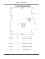
The power supply is connected into terminals 24 (negative) and 25 (positive). The supply voltage is indicated on the
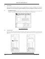
serial number label (Figure 2)
APPLICATION OF VOLTAGES HIGHER THAN THAT STATED FOR THE SUPPLY MAY CAUSE
DAMAGE TO THE INSTRUMENT.
3.2
Sensor Connections
All sensor connections are made to terminals numbered 10,11 & 12 on the instrument.
The inputs are connected as described below.
3.2.1
DC Voltage Inputs
This applies to the high level input device only (IIR-4002-ALM-HL). The signal should be connected between
terminals 11 (positive) and 10 (negative).
3.2.2
DC Current Inputs
This applies to the high-level input device only (IIR-4002-ALM-HL). The signal should be connected between
terminals 11 (positive) and 10 (negative). If the transmitter supply option is fitted, *connect transmitter positive
to terminal 14, transmitter negative to terminal 11 and link terminals 10 & 13.*
3.2.3
Thermocouple Inputs
This applies to the thermocouple input device only, (IIR-4002-ALM-TC). Thermocouples or mV sources are
connected to input terminals 10 (negative) and 11 (positive). The cold junction compensation, where
appropriate, is performed by an integral sensor located close, and thermally connected to, the input terminal.
3.2.4
RTD Inputs
This applies to the resistance thermometer input device only, (IIR-4002-ALM-RTD). RTD’s should be
connected using three identical wires in order that measurement errors due to lead wire resistances can be
eliminated. The sensor common wires should be connected to terminals 10 & 12, the remaining wire going to
terminal 11. If it is necessary to use a two wire sensor then it should be connected between terminals 10 and 11
and an internal link should be fitted (see section 4.0 Trip Configuration); alternatively terminals 10 & 12 can be
externally linked.
*
2 wire transmitter
IIG-9506-04
Page 7