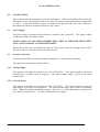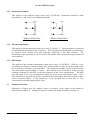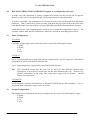
1
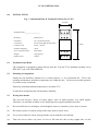
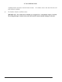
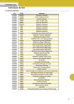
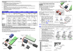
VCON USER MANUAL
IIR - ISOCON FAMILY
OF
ISOLATING SIGNAL CONDITIONERS
VCON
Whilst every effort has been taken to ensure the accuracy of this document, we accept no responsibility
for damage, injury, loss or expense resulting from errors or omissions, and reserve the right of
amendment without notice.
Industrial Interface Research Limited 1995
This document is issued by Industrial Interface Research Ltd and may not be reproduced in any way
without the prior written permission of the company
IIG-9501-03
Page 1
VCON USER MANUAL
CONTENTS
PAGE
Page 2
1.0
INTRODUCTION
3
2.0
UNPACKING
6
3.0
CONNECTIONS
7
4.0
RECONFIGURATION (applies
to re-configurable option units
only)
9
5.0
RECALIBRATION
13
6.0
INSTALLATION
14
7.0
SPECIFICATIONS
15
IIG-9501-03
VCON USER MANUAL
1.0
INTRODUCTION
The VCON range is a family of signal conditioners capable of accepting a wide variety of electrical input
types into an isolated input stage and providing a separate isolated re-transmitted output.
Each unit is a full 3-port isolating device, the input, output and power supply input being isolated from
each other.
In addition, an optional isolated transmitter power supply is available (VCON-HL only).
used to excite any standard 2-wire transmitter, having a maximum supply current of 25mA.
This can be
The instrument is available in three different formats each accepting an input from a different type of
sensor. The different formats are as shown below. Each is available in either MVCON or VCON form,
the MVCON being mains powered whilst the VCON is powered by a low voltage source. This manual
applies specifically to the VCON. Input signal, output signal and power supply information are required
to define any unit exactly. This information, together with a unique serial number, is printed on the side
label of each unit; records of the exact configuration of every product shipped are maintained at the
factory.
1.1
Input Types and Ranges
VCON-HL
Accepts either voltage or current (i.e. high level) inputs with optional transmitter supply or 2 wire
potentiometers (current excitation)/3 wire potentiometers (current or voltage excitation).
In general the limits on signals that can be handled with the accuracy specified in Section 7 are:
DC current
DC voltage
FULL SCALE INPUT
MIN
MAX
50mA
10/A
100mV
300V
MIN SPAN
NOTES
50% full scale
50% full scale
AC current
100mA RMS
10A RMS
50% full scale
Use VCON-TC for Vin <
100mV
45Hz < fin < 450Hz
AC voltage
200mV RMS
250V RMS
50% full scale
45Hz < fin < 450Hz
2 wire
Potentiometer
3 wire
Potentiometer
1 K ohm
1 M ohm
50% of travel
Use VCON RTD for R < 1
K ohm
10 ohm
10 M ohm
50% of travel
All the standard process ranges such as 0-10mA, 4-20mA, 0-20mA, 1-5V and 0-10V are of course
covered.
IIG-9501-03
Page 3
VCON USER MANUAL
VCON -TC
Accepts inputs directly from the following Thermocouple types: J, K, N, T, R, B, E, U, L and S,
alternatively a mV input may be specified. All specified ranges are zero referred - i.e. 0°F, 0°C
or 0 mV, although negative inputs will not damage the unit. Automatic cold junction
compensation will be fitted to thermocouple units, for which either upscale or downscale drive on
break detection are link selectable. The output is not linearised. For standard thermocouples
the operating range will be specified in °C or °F, as required. In general the limits on signals
that can be handled with the accuracy specified in Section 7 are:
INPUT TYPE
mV
J(L)
K
T(U)
E
N
R
S
B
FULL SCALE INPUT
MIN
MAX
4mV
100mV
80°C
1200°C
100°C
1372°C
95°C
400°C
65°C
1000°C
150°C
1300°C
460°C
1768°C
480°C
1760°C
910°C
1820°C
NOTES
Cold junction compensation
will not be fitted
VCON-RTD
Accepts inputs from resistance thermometers such as the PT100 type in 2 or 3 wire configuration.
Additionally 2 wire potentiometers less than 1 Kohm can be accommodated. In general the
measured resistance can be anywhere between zero and 1 K ohm and standard curves such as
PT100 can be linearised. The minimum span must be 10 ohm for the accuracy specified in
Section 7, which corresponds to roughly 30°C for a PT 100 sensor. For standard RTD sensor
types the operating range will be specified in °C and the output will be linearised; otherwise the
range will be specified in ohms without linearisation.
Page 4
IIG-9501-03
VCON USER MANUAL
1.2
Output Types and Ranges:
All members of the VCON family share the same output stage which can provide three types of
output:
OUTPUT FULL SCALE RANGE
MIN
MAX
i) Current Source
ii) Unbuffered voltage
source _
iii) Buffered voltage
source
1mA
into 15 K ohm
MAX
100mV
into 10 K ohm
MIN
100mV
into 100 ohm
MIN
20mA
into 750 ohm
MAX
15V
into 750 K ohm
MIN
20V
into 2K ohm
MIN
Over range limit
(approximate)
+ 10%
+10%
+10%
iv) Current sink*
This includes all standard output ranges such as 0-10mA, 4-20mA, 0-20mA, 1-5V and 0-10V.
_ Unbuffered voltage source outputs may be used with load resistances lower than minimum
specified values, but a span trim will be necessary to give the specified accuracy.
* Current sink option is available by special request - contact factory for details
1.3
Power Supply
Standard power supply requirement is for 24Vdc +/- 10% for specified performance. 5V DC,
12V DC and 24V AC supplies can be catered for by special request - contact factory for details.
Maximum current consumption at 24V DC depends on application as follows:
Current source output, no transmitter supply
Unbuffered voltage source output, no transmitter supply
Buffered voltage source output, no transmitter supply
Additional requirement for transmitter supply or 2/3 wire
potentiometer input (VCON HL only)
IIG-9501-03
I supply max
50mA
50mA
70mA
40mA
Page 5
VCON USER MANUAL
2.0
UNPACKING
Please inspect the instrument carefully for signs of shipping damage. The unit is packaged to
give maximum protection but we can not guarantee that undue mishandling will not have
damaged the instrument. In the case of this unlikely event, please contact your supplier
immediately and retain the packaging for our subsequent inspection.
2.1
Checking the Unit Type
Each unit has a unique serial number label (fig.1 below) on which full details of the configuration
are given. These details should be checked to ensure conformance with your requirement.
Fig. 1 - Serial Number Label
Fig. 2 - VCON Connection Details
Page 6
IIG-9501-03
VCON USER MANUAL
3.0
CONNECTIONS
This section details the instrument connection information. Before proceeding, please check the
information on the serial number label on one side of the unit to ensure that the unit configuration
is correct. Connection details are given on a label on the opposite side of the unit, referring to
the numbered connector terminals as shown in fig.2 above.
3.1
Power Supply
The power supply is connected into terminals 1 (negative) and 2 (positive).
is indicated on the serial number label.
The supply voltage
APPLICATION OF VOLTAGES HIGHER THAN THAT STATED FOR THE SUPPLY
MAY CAUSE DAMAGE TO THE INSTRUMENT.
Ensure that no bare wire protrudes from the rear of the power connector risking a short circuit.
We advise the use of bootlace ferrules on all bare wires.
3.2
Sensor Connections
All sensor connections are made to terminals numbered 4, 5 and 6 on the instrument.
The inputs are connected as described below.
3.2.1
Voltage Inputs
This applies to the high-level input device only (VCON-HL). The signal should be connected
between pins 5 (positive) and 4 (negative). The input voltage range is given on the serial
number label.
3.2.2
Current Inputs
This applies to the high-level input device only (VCON-HL). The signal should be connected
between pins 5 (positive) and 4 (negative). The input current range is given on the serial number
label. When the optional transmitter supply is used, the +ve of the transmitter is connected to
pin 3 and the return to pin 5. No other external links are required.
IIG-9501-03
Page 7
VCON USER MANUAL
3.2.3
Potentiometer Inputs
This applies to the high-level input device only (VCON-HL). Connections should be made
between pins 3, 4 & 5 as per the following diagrams.
3
Rmax
5
4
3.2.4
3
Rmax
5
Rmin
4
Rmin
3 WIRE CONNECTION
2 WIRE CONNECTION
(voltage/current excitation)
(current excitation only)
Thermocouple Inputs
This applies to the thermocouple input device only, (VCON-TC). Thermocouples are connected
to input terminals 4 (negative) and 5 (positive). The cold junction compensation is performed by
an integral sensor located close and thermally connected to the input terminal. The
thermocouple type and range are given on the serial number label, along with output response to
sensor burnout.
3.2.5 RTD Inputs
This applies to the resistance thermometer input device only, (VCON-RTD). RTDs or 2 wire
potentiometers should be connected using three identical wires in order for measurement errors
due to lead wire resistances to be eliminated. The connections should be made as shown on the
side panel label, using terminals 4, 5 and 6. Note that the wires connected to 4 and 6 are the
common connection for the RTD, or the end connection of the 2 wire potentiometer. The RTD
type and range, or the 2 wire potentiometer details are given on the serial number label. If a 2
wire connection is specified this will be recorded on the serial number label and terminals 4 and 6
will be internally linked. A unit shipped for 3 wire operation can be used with a 2 wire
connection by externally linking pins 4 and 6.
3.3
Output Connections
Regardless of output type the common, return or negative of the output circuit should be
connected to terminal 10. Similarly the positive connection should be made to terminal 12.
Page 8
IIG-9501-03
VCON USER MANUAL
4.0
RECONFIGURING THE INSTRUMENT (applies to reconfigurable units only)
In many cases the instrument is factory configured in which case this section can be ignored.
However, if the unit is reconfigurable this will be stated on the serial number label.
In order to reconfigure the instrument it is necessary to remove the circuit board from the plastic
enclosure. This is achieved by gently levering apart both the grey sides at the front of the unit,
such that the black connector pips are released, and sliding the black connector blocks forward.
Inside the unit are various handbag links which are set to obtain the performance required. The
positions of these links and the performance achieved is described in the diagrams overleaf.
4.1
Input Configuration
VCON-HL
Current or voltage input can be selected to achieve any of the following DC inputs:
0-20mA
4-20mA
0-1V
0-10V
VCON-TC
Up to 3 thermocouple types (with cold junction compensation), and mV input (no cold junction
compensation) can be specified for link selection
Up to 4 input temperature ranges can be specified for link selection.
NB.
This nominally means that the unit can be used for four different thermocouple
applications, at least two of which must use the same thermocouple type. However, by
parallel combination of the range links many more ranges may be possible - consult
factory for information.
VCON-RTD
PT100 platinum resistance thermometers to BS1904 or DIN43760 are link selectable. Up to 4
linearised input temperature ranges can be specified.
4.2
Output Configuration
The output of a reconfigurable unit may be configured to give any of the following DC ranges:
0-20mA
4-20mA
0-1V
0-10V
IIG-9501-03
Page 9
VCON USER MANUAL
VCON-HL Link Setting Diagram
S8
S3
S9
S4
S5
S7
S6
INPUT OUTPUT
0(4)-20mA0(4)-20mA
S3
S4
S5
S6
S7 S8 S9
INPUT OUTPUT
S3
S4
S5
S6
S7 S8 S9
0-20mA 4-20mA
4-20mA
0-10v
0-10v
0-10v
0-10v
0-1v
0-10v
4-20mA
4-20mA
0-1v
0-1v
4-20mA
0-20mA
0-10v
0-1v
0-10v
0-10v
0-20mA
0-1v
0-1v
0-20mA
0-1v
0-1v
0-20mA
4-20mA 0-20mA
= LINK POSITION
Page 10
IIG-9501-03
VCON USER MANUAL
VCON-TC Link Setting Diagram
L201
L106
L105
L104
J110
L112
L202
L109
L108
L107
L111
S5
S6
INPUT
T/C RANGE 1
L104 & L107 FITTED
T/C RANGE 2
L105 & L108 FITTED
T/C RANGE 3
L106 & L109 FITTED
mV RANGE
L201 & L202 FITTED
BURNOUT
UPSCALE
J110
DOWNSCALE
J110
OUTPUT
L112 L111
S5
S6
0-10V
4-20mA
= LINK POSITION
IIG-9501-03
Page 11
VCON USER MANUAL
VCON-RTD Link Setting Diagram
S10D
S10C
S10B
S10A
S9D
S9C
S9B
S9A
S8D
S8C
S8B
S8A
(LINEARITY)
L112
(ZERO)
L111
S5
(GAIN)
S6
INPUT
RTD RANGE 1
S8A; S9A & S10A LINKS FITTED
RTD RANGE 2
S8B; S9B & S10B LINKS FITTED
RTD RANGE 3
S8C; S9C & S10C LINKS FITTED
RTD RANGE 4
S8D; S9D & S10D LINKS FITTED
OUTPUT
L111 & L112
S5
S6
0-10V
4-20mA
= LINK POSITION
Page 12
IIG-9501-03
VCON USER MANUAL
5.
RECALIBRATION
All units are factory calibrated; although the user may wish to recalibrate with greater frequency,
a two yearly recalibration interval is adequate for most applications.
In the case of reconfigurable units, recalibration must be carried out after any change of
configuration.
5.1
VCON-HL
With appropriate input values use front panel zero and span pots to obtain desired zero scale and
full scale voltage or current output (preferably into the actual circuit load resistance, for greatest
accuracy). It may be necessary to repeat each adjustment to ensure correct calibration.
5.2
VCON-TC
Generally as for VCON-HL. However, for applications in which automatic cold junction
compensation is used it is necessary to ensure that the thermocouple simulator employed is
switched to automatic cold junction compensation and is at the same ambient temperature as the
VCON-TC. Note that this is not always easy to achieve, especially if the VCON-TC is mounted
in a warm cabinet. In such cases it is best either to calibrate the unit out of panel after allowing
it to reach thermal equilibrium with ambient and the thermocouple simulator (approx. 30 mins), or
to measure the temperature at the VCON-TC connector block and enter this as a manual cold
junction compensation figure in the simulator. (For the most critical applications the optimum
solution is to use a hot box / ice box arrangement, but this is seldom practicable.) If unit output
has been reconfigured to give 4-20mA*, it is necessary to adjust the internal 4mA potentiometer
to give 3.9mA with an input signal of -10mV applied to terminals 4 and 5 before carrying out the
calibration from the front panel pots*.
5.3
VCON-RTD
Generally as for VCON-HL. However, if unit output has been reconfigured to give 4-20mA*, it
is necessary to adjust the internal 4mA potentiometer to give 3.9mA with a short circuit between
input terminals 4 and 5 before carrying out the calibration from the front panel pots.
* Only applies to reconfigurable units.
IIG-9501-03
Page 13
VCON USER MANUAL
6.0
INSTALLATION
Fig. 3 - Installation Data & Terminal Positions For VCON
22.5mm
Installation Data___________________
6.1
Mounting
DIN Rail T35
Orientation
Any (Vertical Preferred)
Connections
Screw Clamp With Pressure Plate
Conductor Size
0.5mm - 4.0 mm
Insulation Stripping
10mm
Screw Terminal Torque
0.4Nm Max.
Weight
100g (approx.)
Depth Of Unit
100mm
1
2
3
4
5
6
75mm
7
8
9
10
11
12
Installation onto Rails
The instrument is designed to mount directly onto the "Top hat" TS35 standard assembly rail to
DIN 46277 part 3/EN 50022/BS5584.
5.2
Mounting Arrangements
Ideally the unit should be mounted in a vertical position, i.e. on a horizontal rail. This is the
optimum orientation to minimise temperature rise within the unit. However successful operation
is possible in any orientation.
Ensure the maximum ambient temperature is less than 55°C.
Good airflow around the unit will maximise reliability.
5.3
Wiring Precautions
The unit can accept a variety of sensor inputs, some of which produce very small signals.
Therefore it is advisable to adhere to the following rules of good installation practice.
(i)
Do not install close to switchgear, electromagnetic starters, contactors, power units or motors.
(ii)
Do not have power or control wiring in the same loom as sensor wires.
(iii)
Use screened cable for sensor wiring with the screen earthed at one end only.
(iv)
Take care not to allow cut pieces of wire to fall onto the unit as they might enter via the
Page 14
IIG-9501-03
VCON USER MANUAL
ventilation holes and cause electrical short circuits.
until wiring is complete.
(v)
if in doubt, remove the units from the rail
Use bootlace ferrules on all bare wires.
IMPORTANT: The connection terminals are designed for a maximum torque of 0.4Nm.
Exceeding this figure is unnecessary and will result in unwarrantable damage to the unit.
IIG-9501-03
Page 15
VCON USER MANUAL
SPECIFICATIONS
All specifications are at 20°C operating ambient with 250Ω output load (current output) unless
otherwise stated.
Accuracy and Response
VCON-HL
Calibration accuracy at zero and full scale
Linearity
Zero drift
Gain drift
Gain dependence on load resistance, RL
+/- 0.05% full scale
+/- 0.1% full scale
+ / - 50ppm full scale /°C
+/- 100ppm /°C
-10ppm / Ω, 0 ≤ RL ≤ 750Ω
Response Time (90% of step change)
30ms typical
VCON-TC
Calibration accuracy at zero and full scale
+/- 0.2% full scale
Cold junction compensation accuracy
+/- 2 ° C over operating temperature
range
Linearity (with respect to thermocouple voltage)
Zero drift
Gain drift
Gain dependence on load resistance, RL
+/- 0.1% full scale
+/- 50ppm full scale /°C
+/- 100ppm /°C
-10ppm / Ω, 0 ≤ RL ≤ 750Ω
Response time (90% of step change)
300ms typical
VCON-RTD
Page 16
Calibration accuracy (at zero and full scale)
Linearity
Zero drift
Gain drift
Gain dependence on load resistance, RL
+/- 0.3°C + / - 0.05% full scale
+/- 0.1% full scale
+/- 50ppm full scale /°C
+/- 100ppm /°C
-10ppm / Ω, 0 ≤ RL ≤ 750Ω
Response time (90% of step change)
40ms typical
IIG-9501-03
VCON USER MANUAL
Power Supply Isolation and Operating Ambient (all types)
Operating Voltage
24V DC +/- 10%
Current consumption *
45mA typical
Input to output to power supply isolation (3
port)
1kV DC
Operating temperature range
0-55°C
Storage temperature range
-40 - 100°C
Operating and storage humidity range
0 - 90% RH
* Upscale output (22mA)
RFI Immunity
All members of the VCON family have been tested, with 4-20mA outputs for RFI immunity to
IEC 801-3 as follows:
Pass condition: Output current varies by less than +/- 1% full scale, any field orientation.
VCON-HL
Field Strength Immunity Level/Vm-1
10
Frequency Range/MHz
27 - 500
Field Strength Immunity Level/Vm-1
10
Frequency Range/MHz
27-429; 441-500
3
27-500
Field Strength Immunity Level/Vm-1
10
Frequency Range/MHz
27-500
VCON-TC
VCON-RTD
50Hz Rejection (load resistance, RL = 500Ω)
VCON-TC
Common mode rejection ratio (CMRR)
130dB
Differential or normal mode rejection ratio
(NMRR)
50dB*
* N.B. 80dB NMRR is available as a special option.
IIG-9501-03
Response time is increased to 600ms typical
Page 17