1
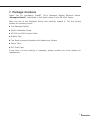
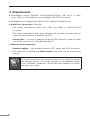
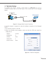
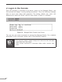
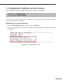
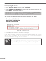
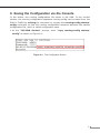
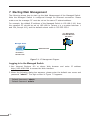
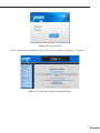
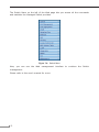
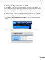
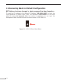
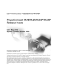
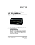
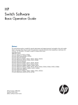
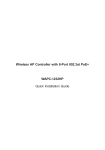
L2/L4 Managed Gigabit Ethernet Switch GS-4210 Series Quick Installation Guide Table of Contents 1. Package Contents........................................................................................ 3 2.Requirements.............................................................................................. 4 3. Terminal Setup............................................................................................ 5 4. Logon to the Console................................................................................... 6 5. Configuring IP Address via the Console......................................................... 7 6. Saving the Configuration via the Console....................................................... 9 7. Starting Web Management..........................................................................10 8. Saving Configuration via the Web................................................................13 9. Recovering Back to Default Configuration......................................................14 10. Customer Support......................................................................................15 1.Package Contents Thank you for purchasing PLANET L2/L4 Managed Gigabit Ethernet Switch. “Managed Switch” mentioned in this Guide refers to the GS-4210 Series. Open the box of the Managed Switch and carefully unpack it. The box should contain the following items: zz The Managed Switch zz Quick Installation Guide zz RS-232 to RJ45 Console Cable zz Rubber Feet zz Two Rack-mounting Brackets with Attachment Screws zz Power Cord zz SFP Dust Caps If any item is found missing or damaged, please contact your local reseller for replacement. 3 2.Requirements zz Workstations running Windows XP/2003/Vista/7/8/2008, MAC OS X or later, Linux, UNIX, or other platforms are compatible with TCP/IP protocols. zz Workstations are installed with Ethernet NIC (Network Interface Card) zz Serial Port Connection (Terminal) The above Workstations come with COM Port (DB9) or USB-to-RS-232 converter. The above Workstations have been installed with terminal emulator, such as Hyper Terminal included in Windows XP/2003. Serial cable -- one end is attached to the RS-232 serial port, while the other end to the console port of the Managed Switch. zz Ethernet Port Connection Network cables -- Use standard network (UTP) cables with RJ45 connectors. The above PC is installed with Web browser and JAVA runtime environment plug-in. Note 4 It is recommended to use Internet Explore 8.0 or above to access the Managed Switch. If the Web interface of the Managed Switch is not accessible, please turn off the anti-virus software or firewall and then try it again. 3.Terminal Setup To configure the system, connect a serial cable to a COM port on a PC or notebook computer and to the RJ45 type of the console port of the Managed Switch. PC / Workstation with Terminal Emulation Software Managed Switch RS-232 to RJ-45 Cable Serial Port RJ-45 Console Port Figure 3-1 Managed Switch Console Connectivity A terminal program is required to make the software connection to the Managed Switch. 1.Run terminal program on the OS. 2.When the following screen appears, make sure that the COM port should be configured as: Baud : 115200 Data bits : 8 Parity : None Stop bits : 1 Flow control : None Figure 3-2: COM Port Configuration 5 4.Logon to the Console Once the terminal is connected to the device, power on the Managed Switch, and the terminal will display “running testing procedures”. Then, the following message asks to log-in user name and password. The factory default user name and password are shown as follows, and the login screen in Figure 4-1 appears. Username: admin Password: admin Figure 4-1: Managed Switch Console Login Screen The user can now enter commands to manage the Managed Switch. For a detailed description of the commands, please refer to the following chapters. Note 6 1. For security reason, please change and memorize the new password after this first setup. 2. Only accept command in lowercase letter under console interface. 5.Configuring IP Address via the Console The Managed Switch is shipped with default IP address as follows: IP Address: 192.168.0.100 Subnet Mask: 255.255.255.0 To check the current IP address or modify a new IP address for the Switch, please use the procedures as follows: Show the current IP address 1.At the “GS-4210 Series#” prompt, enter “show ip”. 2.The screen displays the current IP address, Subnet Mask and Gateway as shown in Figure 5-1. Figure 5-1: IP Information Screen 7 Configuring IP address 3.At the “GS-4210 Series#” prompt, enter “configure”. 4.At the “GS-4210 Series(config)#” prompt, enter the following command and press <Enter> as shown in Figure 5-2. GS-4210 Series(config)# ip address 192.168.1.100 mask 255.255.255.0 GS-4210 Series(config)# ip default-gateway 192.168.1.254 The previous command would apply the following settings for the Switch. IP Address: 192.168.1.100 Subnet Mask: 255.255.255.0 Gateway: 192.168.1.254 Figure 5-2: IP Address Screen 5.Repeat Step 1 to check if the IP address is changed. If the IP is successfully configured, the Managed Switch will apply the new IP address setting immediately. You can access the Web interface of the GS-4210 Managed Switch Series through the new IP address. Note 8 If you are not familiar with console command or the related parameter, enter “?” anytime in console to get the help description. 6.Saving the Configuration via the Console In the switch, the running configuration file stores in the RAM. In the current version, the running configuration sequence running-config can be saved from the RAM to FLASH by writing the command or copying the running-config startupconfig command, so that the running configuration sequence becomes the startup configuration file, which is called configuration save. 1.At the “GS-4210 Series#” prompt, enter “copy running-config startupconfig” as shown in Figure 6-1. Figure 6-1: The Configuration Screen 9 7.Starting Web Management The following shows how to start up the Web Management of the Managed Switch. Note the Managed Switch is configured through an Ethernet connection. Please make sure the manager PC must be set on the same IP subnet address. For example, the default IP address of the Managed Switch is 192.168.0.100, then the manager PC should be set at 192.168.0.x (where x is a number between 1 and 254, except 100), and the default subnet mask is 255.255.255.0. PC / Workstation with Web Browser 192.168.0.x Managed Switch RJ45/UTP Cable IP Address: 192.168.0.100 Figure 7-1: IP Management Diagram Logging in to the Managed Switch 1.Use Internet Explorer 8.0 or above Web browser and enter IP address http://192.168.0.100 to access the Web interface. 2.When the following dialog box appears, please enter the default user name and password “admin”. The login screen in Figure 7-2 appears. Default Username: admin Default Password: admin 10 Figure 7-2: Login Screen 3.After entering the password, the main screen appears as Figure 7-3 shows. Figure 7-3: Web Main Screen of Managed Switch 11 The Switch Menu on the left of the Web page lets you access all the commands and statistics the Managed Switch provides. Figure 7-4: Switch Menu Now, you can use the Web management interface to continue the Switch management. Please refer to the user’s manual for more. 12 8.Saving Configuration via the Web In the Managed Switch, the running configuration file stores in the RAM. In the current version, the running configuration sequence of running-config can be saved from the RAM to FLASH by “Save Configurations to FLASH” function, so that the running configuration sequence becomes the startup configuration file, which is called configuration save. To save all applied changes and set the current configuration as a startup configuration, the startup-configuration file will be loaded automatically across a system reboot. 1.Click “Save > Save Configurations to FLASH” to login “Configuration Manager” Page. 2.Press the “Apply” button to save running configuration to start up configuration. 13 9.Recovering Back to Default Configuration IP Address has been changed or admin password has been forgotten – To reset the IP address to the default IP Address “192.168.0.100” or reset the login password to default value, press the hardware reset button on the front panel for about 10 seconds. After the device is rebooted, you can login the management Web interface within the same subnet of 192.168.0.xx. RESET Figure 9-1: GS-4210 Series Reset Button 14 10. Customer Support Thank you for purchasing PLANET products. You can browse our online FAQ resource and User’s Manual on PLANET Web site first to check if it could solve your issue. If you need more support information, please contact PLANET switch support team. PLANET online FAQ : http://www.planet.com.tw/en/support/faq.php?type=1 Switch support team mail address : [email protected] GS-4210 Series User’s Manual : http://www.planet.com.tw/en/support/download.php?type1=1&model=&type=3 (Please select your switch model name from Product Model drop down menu) Copyright © PLANET Technology Corp. 2014. Contents are subject to revision without prior notice. PLANET is a registered trademark of PLANET Technology Corp. All other trademarks belong to their respective owners. 15