1
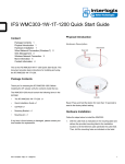
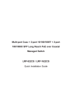
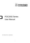
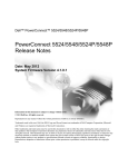
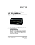
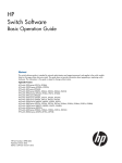
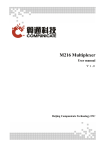
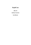
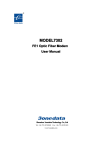
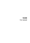
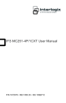
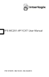
IFS POC2502 Series Quick Start Guide Content Package Contents 1 Requirements 1 Terminal Setup 2 Logon to Console 2 Configuring IP Address 2 Saving the Configuration via the Console 3 Starting Web Management 3 Starting Long Reach PoE Communication 4 Saving the Configuration via the Web 5 Recovering Back to Default Configuration 6 Contact information 6 • RS-232 to RJ45 Console Cable x 1 • SFP Dust Cap x 2 • BNC Female Dust Cap x 8 (POC2502-8CXP) • BNC Female Dust Cap x 16 (POC2502-16CXP) • Warning Sticker x 8 (POC2502-8CXP) • Warning Sticker x 16 (POC2502-16CXP) • Rack-mount Accessory Kit x 1 If any item is found missing or damaged, please contact your local reseller for replacement. Requirements This is the IFS NS4802-24P-4S-2X Quick Start Guide. This document provides basic instructions for installing and using the IFS NS4802-24P-4S-2X. • Package Contents • Workstations running Windows XP/2003/Vista/7/8/2008, or other platforms are compatible with TCP/IP protocols. Workstations are installed with Ethernet NIC (Network Interface Card) Thank you for purchasing IFS - Multi-port Coax + 2-port 10/100/1000T + 2-port 100/1000X SFP Long Reach PoE over Coaxial Managed Switch The description of this model is shown below: POC25028CXP-2T-2S 8-port Coax + 2-port 10/100/1000T + 2-port 100/1000X SFP Long Reach PoE over Coaxial Managed Switch POC250216CXP-2T-2S 16-port Coax + 2-port 10/100/1000T + 2-port 100/1000X SFP Long Reach PoE over Coaxial Managed Switch • Serial Port Connection (Terminal) • The above Workstations come with COM Port (DB9) or USB-to-RS232 converter. • The above Workstations have been installed with terminal emulator, such as Hyper Terminal included in Windows XP/2003. • Serial cable -- one end is attached to the RS232 serial port, while the others end to the console port of the Managed Switch. “POC2502 Managed Switch” is used as an alternative name in this Quick Installation Guide. Open the box of the POC2502 Managed Switch and carefully unpack it. The box should contain the following items: • The POC2502 Managed Switch x 1 • Quick Installation Guide x 1 • Rubber Feet x 4 • Power Cord x 1 P/N 1073046 • REV A • 10SEP15 • Ethernet Port Connection • Network cables -- Use standard network (UTP) cables with RJ45 connectors. • The above PC is installed with Web Browser and JAVA runtime environment plug-in. 1 It is recommended to use Internet Explore 8.0 or Logon to Console above to access the Managed Switch. If the Web interface of the Managed Switch is not accessible, please turn off the anti-virus software or firewall and then try it again. Terminal Setup To configure the system, connect a serial cable to a COM port on a PC or notebook computer and to RJ45 type of serial port of the Managed Switch. Once the terminal is connected to the device, power on the Managed Switch and the terminal will display “running testing procedures”. Then, the following message asks to log-in user name and password. The factory default user name and password are shown as follows and the login screen in Figure 3 appears. Username: admin Password: admin Figure 3: POC2502 Managed Switch Console Login Screen Figure 1: Managed Switch Console Connectivity The user can now enter commands to manage the Managed Switch. For a detailed description of the commands, please refer to the following chapters. 1. A terminal program is required to make the software connection to the Managed Switch. 1. Run terminal program on the OS. 2. When the following screen appears, make sure that the COM port should be configured as: For security reasons, please change and memorize the new password after this first setup. 2. Only accept command in lowercase letter under console interface. Configuring IP Address ♦ Baud : 115200 ♦ Data bits :8 The Managed Switch is shipped with default IP address shown ♦ Parity : None below. ♦ Stop bits :1 IP Address: 192.168.0.100 Subnet Mask: 255.255.255.0 ♦ Flow control : None To check the current IP address or modify a new IP address for the Switch, please use the procedures as follows: Figure 2: COM Port Configuration 2 Show the current IP Address 1. At the “POC2502 Series#” prompt, enter “show ip ”. 2. The screen displays the current IP address as shown in Figure 3. Figure 3: IP Information Screen IFS POC2502 Series Quick Start Guide Configuring IP Address 3. At the “POC2502 Series#” prompt, enter “configure”. 4. At the “POC2502 Series (config)#” prompt, enter the following command and press <Enter> as shown in Figure 4. POC2502 Series(config)# ip address 192.168.1.100 Figure 5: The Configuration Screen Starting Web Management mask 255.255.255.0 POC2502 Series(config)# ip default-gateway The following shows how to start up the Web Management of 192.168.1.254 the POC2502 Managed Switch. Note, the POC2502 Managed Switch is configured through an Ethernet connection. Please The previous command would apply the following settings for the Switch. IP Address: 192.168.1.100 Subnet Mask: 255.255.255.0 Gateway: 192.168.1.254 make sure the manager PC must be set on the same IP subnet address. For example, the default IP address of the POC2502 Managed Switch is 192.168.0.100, then the manager PC should be set at 192.168.0.x (where x is a number between 1 and 254, except 100), and the default subnet mask is 255.255.255.0. Figure 4: IP Address Screen 5. Repeat Step 1 to check if the IP address is changed. If the IP is successfully configured, the POC2502 Managed Switch will apply the new IP address setting immediately. You can access the Web interface of the POC2502 Managed Switch through the new IP address. Figure 6: IP Management Diagram Logging in to the Managed Switch 1. Use Internet Explorer 8.0 or above Web browser and enter IP address http://192.168.0.100 to access the Web interface. 2. When the following dialog box appears, please enter the default user name and password “admin”. The login screen in Figure 7 appears. If you are not familiar with the console command or the related parameter, enter “?” anytime in console to get the help description. Default Username: admin Saving the Configuration via the Console Default Password: admin In the switch, the running configuration file stores in the RAM. In the current version, the running configuration sequence running-config can be saved from the RAM to FLASH by writing the command or copying the running-config startupconfig command, so that the running configuration sequence becomes the startup configuration file, which is called configuration save. 1. At the “POC2502 Series#” prompt, enter “copy runningconfig startup-config” as shown in Figure 5. Figure 7: Login Screen IFS POC2502 Series Quick Start Guide 3 After entering the password, the main screen appears as Figure 8 shows. The POC2502 Managed Switch is configured DISABLED Long Reach PoE function as default. Connect the Coaxial Cable 1. Insert the coaxial cable with one side being the 75ΩBNC plug connector into the Long Reach Ethernet coaxial interface. 2. Connect the other end of the cable to a device with Long Reach Ethernet coaxial Extender installed. 3. Tight the BNC male connector gently. 4. Enable Long Reach Power over Ethernet function for the all POC2502 ports from Web UI. 5. Check the LNK LED of the Long Reach Power over Ethernet interface on the front of the POC2502 Managed Switch. Ensure that the Long Reach Power over Ethernet interface is operating correctly. Figure 8: Web Main Screen of POC2502 Managed Switch The Switch Menu on the left of the Web page lets you access all the commands and statistics the POC2502 Managed Switch provides. Figure 9: Switch Menu Now, you can use the Web management interface to continue the Switch management. Please refer to the user’s manual for more information. Now, you can use the Web management interface to continue the Switch management. For more detailed switch configuration, please refer to the user’s manual. Starting Long Reach PoE Communication The following shows how to start up the Long Reach PoE Communication of the POC2502 Managed Switch from Web Management. 4 1. Before installation, please consider the distance and watts value demand for PD devices. The POC2502 Managed Switch and POC2502 Extender PoE output capacity and upload / download performance depend on the length of coaxial cable. You can refer to user manual chapter 1.5 for more information. 2. As there are various resistance values in the category of RG-59/U or RG-6/U cable, the actual data rate will vary on the quality of the copper wire and environmental factors. IFS POC2502 Series Quick Start Guide Remove the connected the Coaxial Cable 1. 2. Make sure there is no network activity anymore Disable Long Reach Power over Ethernet function for the all POC2502 ports from Web UI. 1. The package contains warning stickers, which should be stuck on the coaxial cable connector before using IFS POC252-1CX-1P extender. If connected with Non-IFS POC252 series extender equipment, it might cause damage to the equipment. ! For connection to POC Extenders only. NOT for direct camera connections. Note: Power at BNC ports are off by default. To enable POC power at each BNC connector, please consult the manual. 2. After POC2502 PoE port enabled, the center pin of the coaxial cable is with electricity. Do not touch center pin or connect this end to any nonIFS POC2502 equipment. 3. 4. Loose the BNC male connector gently. Pull out the coaxial cable gently. Saving the Configuration via the Web In the POC2502 Managed Switch, the running configuration file stores in the RAM. In the current version, the running configuration sequence of running-config can be saved from the RAM to FLASH by ”Save Configurations to FLASH” function, so that the running configuration sequence becomes the startup configuration file, which is called configuration save. To save all applied changes and set the current configuration as a startup configuration, the startup-configuration file will be loaded automatically across a system reboot. Never pull out the coaxial cable without disabled Long Reach Power over Ethernet function for the port from Web UI. Directly pulling out the coaxial cable could damage the Long Reach Ethernet coaxial Extender and the BNC female connector of the POC2502 Managed Switch. IFS POC2502 Series Quick Start Guide 1. Click ”Save > Save Configurations to FLASH” to login to the “Configuration Manager” Page. 2. Press the “Apply” button to save running configuration to startup configuration. 5 Recovering Back to Default Configuration IP Address has been changed or admin password has been forgotten – To reset the IP address to the default IP Address “192.168.0.100” or reset the login password to default value, press the hardware reset button on the front panel for about 10 seconds. After the device is rebooted, you can login the management Web interface within the same subnet of 192.168.0.xx. Figure 10: POC2502-8CXP Reset Button This reset would be the same on the POC2502-16CXP-2T-2S. Contact information www.interlogix.com or www.utcfssecurityproducts.eu. For customer support, see www.interlogix.com/customersupport . © 2015 United Technologies Corporation Interlogix is part of UTC Climate Controls & Security, a unit of United Technologies Corporation. All rights reserved. 6 IFS POC2502 Series Quick Start Guide