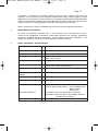
1
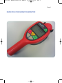
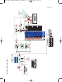
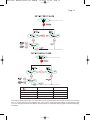
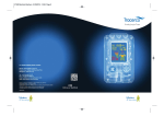
58209 T401 MANUAL:58209 T401 MANUAL 10/8/09 09:29 Page 1 TRACERCO™ Contamination Monitor Instruction and Maintenance Manual for Model No. T401 (Incorporating Model T403) Customer Notice: Please note that the T401 is NOT an Intrinsically Safe Monitor and should not be confused with the TRACERCO™ T201 Contamination Monitor which does meet Intrinsic Safety Standards. 58209 T401 MANUAL:58209 T401 MANUAL 10/8/09 09:29 Page 2 Page 2 CONTENTS 1. General Description 4 2. Operational Safety 4 3. Post-Delivery Checks 4 4. 4.1 4.2 4.3 4.4 4.5 4.6 4.7 Operational Features Switch On Speaker Backlight Low Battery Pre-Set Alarm Detector Probe Calibration 5 5 5 5 5 5 6 6 5. 5.1 5.2 5.3 5.4 5.5 5.6 5.7 5.8 5.9 5.10 5.11 Measurement of Radiation Contamination Procedure Bargraph Reading Digital Numeric Display Peak Display Mode / Select Nuclide Calibration Selection Carry Out a ‘Background Count’ Carry Out a ‘Nuclide Measurement’ Nuclide Options Operational Range Setting Alarm Trip Levels 7 7 7 7 7 8 8 8 8 9 9 11 6. 6.1 6.2 6.3 6.4 Detector Probe Probe Retained in Monitor Yoke Remote Probe / Yoke Assembly Remote Probe with Telescopic Extension Arm Remote Probe Cable Extension 13 13 13 13 13 7. 7.1 7.2 7.3 Maintenance & Calibration Battery Replacement General Maintenance Repair & Calibration 14 14 14 14 8. Information Database 15 9. 9.1 9.2 Basic Technical Specification Additional Information or Monitor Calibration Affects of Gamma Radiation 15 16 16 10. Hints for Radiation Contamination Monitoring 17 11. Warranty 17 12. Health & Safety 18 58209 T401 MANUAL:58209 T401 MANUAL 10/8/09 09:29 Page 3 Page 3 RADIATION CONTAMINATION MONITOR 58209 T401 MANUAL:58209 T401 MANUAL 10/8/09 09:29 Page 4 Page 4 1. GENERAL DESCRIPTION The T401 is a portable battery operated radiation contamination monitor, capable of measuring alpha, beta and gamma radiation over a wide range of energies. Radiation detection is carried out using a thin window Geiger Muller Tube located in a detachable probe adjacent to the head of the monitor. Tracerco has extensive experience of the practical difficulties which may be encountered when attempting to carry out contamination monitoring of both man-made and naturally occurring radioactivity under hostile and restrictive environmental conditions, particularly those which relate to the Chemical, Mining, Nuclear and Oil and Gas Industries. The T401 has been designed to address many of these practical issues in providing a monitor which is reliable, versatile, easy to use and capable of operating in adverse environmental conditions. The T403 is similar in all respects to the T401 with the exception that the probe can be deployed up to 10 metres from the body of the monitor (see Section 4.6). A key feature of the T401 is the capability to allow pre-programming of detection efficiency data for a wide range of radionuclides enabling recorded counts/sec to be automatically translated into more radiologically significant units of Bq/cm2. There are additional design elements which are fully described in this manual and combine to make the T401 an invaluable instrument for use in radiation contamination monitoring. 2. OPERATIONAL SAFETY The TRACERCO™ T401 Contamination Monitor is a portable battery operated device which has been designed to exacting standards to operate reliably in adverse environments. Typical battery life is around 100 hours. A ‘LO BATT’ warning appears on screen when the residual capacity reduces to about 4 hours. When the residual charge is exhausted, the screen clears. A selectable backlight facility allows measurements to be made under dark or low light conditions. (Note that the extended use of this function will significantly reduce battery life). An audible response is also available to complement visual measurements. In the event of a GM tube failure or circuit malfunction which interrupts the radiation detection signal, the screen will indicate the following warning message “ERR1”. 3. POST DELIVERY CHECKS All monitors supplied by Tracerco have been fully inspected, tested and calibrated prior to shipping. The monitor will be fitted with a new battery and available for immediate operation. Each monitor is supplied in a protective overpack for transportation (customers may purchase an alternative, special transport and storage case). All monitors should reach the customer in perfect working order. In the unlikely occurrence of a problem, please contact Tracerco immediately (contact numbers are provided within this manual). 58209 T401 MANUAL:58209 T401 MANUAL 10/8/09 09:29 Page 5 Page 5 PLEASE ENSURE THAT THE MONITOR RADIATION TEST AND CALIBRATION CERTIFICATE IS PRESENT IN THE PACK. (Certificates should be filed in a safe place for future reference. In the event of difficulties, duplicate certificates can be provided by Tracerco free of charge). 4. OPERATIONAL FEATURES Owners should also refer to the Main Menu Structure for Functionality. 4.1 Switch On The monitor is activated by pressing the RED on / off switch. This switch has a toggle action – press for ON and press again for OFF. In the absence of any significant local radiation sources the meter will register incident background radiation which will vary with geographical location. A typical background reading on the monitor would be of the order of 0.5 – 1 count per second. Please note that there may be a slight delay of one or two seconds between physically operating the switch and the screen clearing of information. 4.2 Speaker Pressing the GREY switch with the speaker symbol activates the internal speaker. The speaker provides an audible clicking sound whose rate is proportionate to the amount of radiation registered by the detector. The speaker may be silenced by re-pressing the GREY switch. The speaker symbol shows on screen when the audible option has been selected. Battery life is extended with the speaker off. 4.3 Backlight The monitor display is fitted with a backlight, which is available for use in situations of low ambient light intensity. The GREY switch with the sunburst symbol is pressed to activate the backlight facility. Since the backlight significantly increases the current drain on the battery, the pushbutton switch is designed for contact operation only ie., depressing the switch activates the backlight and releasing the switch cancels the light. 4.4 Low Battery The monitor is equipped to display a “LO BATT” message. Although it is recommended that the battery be replaced as soon as this message is activated, it might be expected that under normal conditions, the monitor is capable of operating for a further 4 hours. 4.5 Pre-Set Alarm The monitor is equipped with an alarm function which the operator can pre-set, within prescribed limits, to any desired level of counts per second (cps) or Bq/cm2. If an alarm level is set in the cps mode, it will not be available when in the Bq/cm2 mode (and visa versa). An alarm is a continuous high frequency tone whenever the measured reading exceeds the pre-set value. The alarm may be deactivated by the operator. There is no mute (accept facility) for the alarm. Alarm activation is indicated by a flashing loudspeaker icon. 58209 T401 MANUAL:58209 T401 MANUAL 10/8/09 09:29 Page 6 Page 6 4.6 Detector Probe The T401 Contamination Monitor is equipped with a thin window Geiger Muller detector located in a special probe attached to the head of the monitor. The detector has the capability to measure alpha, beta and gamma radiation over a wide range of energies and its delicate, recessed front window is protected by an open mesh steel grille during use. (Although the mesh provides protection from a rupture of the thin window by large objects during use, the window remains delicate and vulnerable to puncture by thin sharp objects and care should be exercised at all times when carrying out monitoring operations). The detector probe normally rests within a special yoke attached to the monitor, with the face of the probe orientated into and protected by the main body of the monitor. This orientation is recommended during storage or transportation. The probe is connected to the monitor via a flexible cable which is normally retained within the horseshoe-shaped skid attached to the monitor. The probe is designed to be used in three possible ways during monitoring operations:1. Probe remains attached to the monitor yoke but rotated to suit monitoring requirements. 2. Probe and the yoke are decoupled from the body of the monitor for hand operation. The flexible cable allows remote operation up to 1.5-metres from the body of the monitor. 3. Probe and yoke are removed from the body of the monitor and attached to the extendable arm (purchased option). The orientation of the probe is adjustable relative to the extension arm to provide maximum flexibility when monitoring. (Further information on these monitoring options is provided in section 6 describing the detector probe). A special variant of the T401 monitor is the T403 which has a 10 metre long cable option connecting the body of the monitor to the detector probe. This model is designed to facilitate the monitoring of pipes and drains. A sectional extension rod is available to deploy the probe over such distances. In all other respects the T403 is operationally identical to the T401. 4.7 Calibration Current UK legislation requires that all operational radiation monitors are subject to annual inspection and testing. This requirement includes for performance checks and where appropriate, recalibration of the monitor. On switching on the contamination monitor, the next calibration check due date will register automatically on the screen for approximately 2 seconds. This date will indicate the 12-month anniversary of the current calibration. All Tracerco radiation monitors are checked and calibrated immediately prior to despatch to the customer. Following this initial procedure (or the annual inspection and calibration check), Tracerco operatives will re-set the next calibration check due date within the software of the monitor. For further information on the calibration procedure refer to sections 7.3 and 9. 58209 T401 MANUAL:58209 T401 MANUAL 10/8/09 09:29 Page 7 Page 7 5. MEASUREMENT OF RADIATION CONTAMINATION (It may be a help to read this section referencing the function flow chart on page 10) 5.1 Procedure Switching on the monitor will display all available segments for approximately 2 seconds (as shown below). A check should be performed for any missing segments For the following 2 seconds, the next ‘Cal Due’ date will show using a MM-YY format. The monitor then enters normal operation (cps mode). 5.2 Bargraph Display This display provides a reading in the range 0cps – 1000 cps. Maximum resolution is provided in the range 0 – 10cps, which is considered to be the most critical range for routine waste characterisation purposes. If the probe is exposed to activity levels which exceed the maximum count rate of 1000 cps, the bargraph will remain at full scale deflection until the source of radiation is removed. 5.3 Digital Numeric Display There is a 5 digit digital display. For radiation levels below 100cps or 100 Bq/cm2 the monitor will give a reading to 2 decimal places. The maximum indication is 4000 cps or its equivalent in Bq/cm2 5.4 Peak Display The meter is capable of numerically indicating the highest radiation level to which the probe has been exposed since the instrument was switched on. Switching off will clear this reading. Pressing the green “PEAK” button will show this reading. (During this period peak value continues to be updated). A second press of the “PEAK” button during this period will return monitor to normal function. Pressing “SELECT / RESET” button whilst displaying the peak reading will reset the peak reading to zero. 5.5 Mode / Select The yellow “MODE” and green “SELECT / RESET” buttons are required when accessing various functions associated with the monitor. 58209 T401 MANUAL:58209 T401 MANUAL 10/8/09 09:29 Page 8 Page 8 5.6 Nuclide Calibration Selection In order to carry out a radiological assessment of the data obtained during contamination monitoring, it is necessary to know the efficiency response of the monitor for the radionuclide under investigation and to make the appropriate calculations. The T401 has been specially developed to provide a direct reading of the level of contamination in Bq/cm2 for a number of radionuclides which the operator can pre-select. The efficiency calibration response functions of the monitor for various radionuclides are pre-programmed into the instrument software. These functions are also checked and reset during the annual inspection and calibration process. In order to carry out a ‘statistically’ effective measurement of surface activity it is necessary to accumulate counts over a reasonable timeframe and to make appropriate corrections for ‘background’ levels of radiation. The following procedures should be followed when carrying out a radiological measurement:- 5.7 Carry Out a “Background” Count After switch on press the yellow “MODE” button to select the background function (allow 5 seconds for the display function to normalise). The “BGnd” message will appear on the screen. Confirm this choice by pressing the “SELECT / RESET” button. The monitor will commence a background radiation count which will continue for a period which, based on environmental levels, is sufficient to provide a statistically acceptable count. A typical count duration is 60 seconds. The unit has been pre-programmed to accumulate and terminate this count. During the count period, the display will show the real time integration of counts. After the count has been automatically terminated, the display will show the mean value of the ‘Background’ count in counts per second. This value will be automatically stored in memory. Press the “SELECT / RESET” button to accept this count and move to Bq/cm2 monitoring. Alternatively press the ‘MODE’ button to repeat a background count. The background count will remain in memory after the monitor has been turned off. This value will only be updated when the above procedure for carrying out a background count is repeated. 5.8 Carry Out a “Nuclide Measurement” Following selection of the background count the display moves to the Bq/cm2 screen. Confirm this choice by pressing the “SELECT / RESET” button, whereupon the message ‘NUCL’ will appear on the screen. The previously selected radionuclide will also appear at the base of the screen. Scroll back and forth through the various nuclide options using the ‘MODE’ and “PEAK” buttons to locate the one which is required and confirm your choice by pressing the “SELECT / RESET” button. This operation will also start the count integration. (Note; there are 16 radionuclide options and one cps option, which, if chosen by pressing “SELECT / RESET”, will revert the monitor to a cps display. Pressing the ‘MODE’ button will continue the scrolling operation, pressing the “PEAK” button will scroll in opposite direction). The unit will display the value of “Bq/cm2” in real time. Pressing the “MODE” button whilst in “Bq/cm2” will return the digital display and associated functions to cps mode. (NB: The analogue display will always display “live” cps, irrespective of which functions are being selected in the digital display). 58209 T401 MANUAL:58209 T401 MANUAL 10/8/09 09:29 Page 9 Page 9 Each nuclide has a different response factor ie the number of counts detected by the monitor per becquerel of activity and the correct value of activity will only be displayed if the operator has selected the actual nuclide which is being measure. A mis-selection will result in either a higher or a lower value than the result, depending on the exact circumstances. 5.9 Nuclide Options:The T401 monitor has been pre-calibrated to measure the list of nuclides given below. These nuclides have been shown to be of general interest for a wide range of environments where contamination monitoring might be required. In the event that the operator requires calibration against a range of alternative isotopes, Tracerco will endeavour to provide the appropriate functionality (subject to the availability of suitable calibration materials). These options are currently listed on the screen as Nuclide 1 to 9. The customer will be required to specify any additional nuclide calibrations at the time of purchase (Subject to Tracerco having capability to source the appropriate radionuclides in a form suitable for calibration). The identity of the radionuclides will remain on the screen as 1 to 9. It is recommended that special calibration requirements be discussed with a representative of the Tracerco monitor calibration and repair service (contact details on page 17). Option Option Option Option Option Option Option Option Option Option Option Option Option Option Option Option Option Option Option Option Option Option Option 1 2 3 4 5 6 7 8 9 10 11 12 13 14 15 16 17 18 19 20 21 22 23 : : : : : : : : : : : : : : : : : : : : : : : Americium-241 Carbon-14 Chlorine-36 Lead-210 (d) Lead-210 (w) Radium-226 (d) Radium-226 (w) Strontium-90 Cobalt-60 Phosphorus-32 Plutonium-239 Uranium-238 Caesium-137 Polonium-210 Nuclide 1 Nuclide 2 Nuclide 3 Nuclide 4 Nuclide 5 Nuclide 6 Nuclide 7 Nuclide 8 Nuclide 9 Wet and dry options (w) (d) provide alternative response coefficients to simulate the practical conditions under which naturally occurring radioactivity is monitored in the environment (particularly within the oil and gas industry). Calibration for Lead-210 assumes an equilibrium with daughter products Bismuth-210 and Polonium-210. 5.10 Operational Ranges Bargraph scale : 0 → 1000cps. Numeric scale : 0 → 4000cps. PRESS THE RESET BUTTON TO RESET THE PEAK VALUE RESET CPS PEAK DISPLAY T401 FUNCTIONAL DIAGRAM Strontium-90 Nuclide Phosphorus-32 Nuclide Chlorine-36 Nuclide Carbon-14 Nuclide Uranium-238 Nuclide 09:29 Cobalt-60 Nuclide Caesium-137 Nuclide Lead-210 (d) Nuclide Plutonium-239 Nuclide Radium-226 Nuclide Americium-241 Nuclide 10/8/09 Lead-210 (w) Nuclide Option 9 Nuclide Option 8 Nuclide Option 7 Nuclide Option 6 Nuclide Option 5 Nuclide Option 4 Nuclide Option 3 Nuclide Option 2 Nuclide Option 1 Nuclide Bq/cm2 PEAK DISPLAY RESET PRESS THE RESET BUTTON TO RESET THE PEAK VALUE 58209 T401 MANUAL:58209 T401 MANUAL Page 10 Page 10 58209 T401 MANUAL:58209 T401 MANUAL 10/8/09 09:29 Page 11 Page 11 5.11 Setting Alarm Trip Levels The T401 is equipped with an alarm function which can be set by the operator. The alarm is a continuous high-pitched note and operates whenever the monitor reading exceeds a pre-set trip level. The alarm trip level can be set in either counts / sec or Becquerels / cm2 mode. The incremental settings for the alarms are as follows:Range (Counts / Sec) 0 → 10 10 → 50 50 → 100 100 → 1000 1000 → 4000 Increment 1.0 5.0 10.0 100 500 Maximum alarm trip level is 4000 cps. Range (Becquerels / cm2) 0 → 1.0 1.0 → 10 10 → 500 Increment 0.1 1.0 10 Maximum alarm trip level is 500 Bq / cm2. Sounder Options One normal press of the speaker button will turn on the sounder which will “click” in response to radiation. In this (non-alarm) mode the speaker symbol will be on continuously. A flashing speaker symbol indicates the alarm is set. For details, refer to page 12. If the speaker symbol is showing an extended repeat sequence, it indicates that the alarm mode and sounder are both activated. If the speaker symbol is absent from the screen, it indicates that both audible response and alarm setting is OFF. It should be noted that on switching on, the monitor will retain the previous alarm trip level settings and speaker status. To Set the Alarm Trip Level The following flow chart identifies the process for setting an alarm trip level in cps and Bq / cm2 mode. 58209 T401 MANUAL:58209 T401 MANUAL 10/8/09 09:29 Page 12 Page 12 SYMBOL OFF CONTINOUS SHORT FLASH LONG FLASH SOUNDER ALARM OFF ON OFF ON OFF OFF ON ON It should be noted that the Bq / cm2 alarm will only be operative when the monitor is being used with the Bq / cm2 mode selected on the digital scale. Since only a single value trip setting can be entered in Bq / cm2, the operator must ensure that the selected value is consistent with the type of radionuclide being monitored. 58209 T401 MANUAL:58209 T401 MANUAL 10/8/09 09:29 Page 13 Page 13 6. DETECTOR PROBE The T401 utilises a thin window Geiger Muller probe for the detection of alpha, beta and gamma radiation over a wide range of energies. The probe has been designed to provide a high degree of flexibility in the manner in which it can be deployed for contamination monitoring. The following are examples of the key operational options:- 6.1 Probe Retained in Monitor Yoke During storage and transport, it is recommended that the probe is rotated to its nonoperational position so that the sensitive window is protected by the body of the radiation monitor. The probe is secured in the yoke by a castellated ratchet mechanism with a positive retention pressure exerted by special o-ring seals. The probe can be rotated to various orientations within the yoke. The monitor can be operated with the probe and yoke remaining attached to the lower skid arrangement. The face of the probe should be held some 2mm from the surface being measured to ensure optimal operation and replicate the conditions under which nuclide calibrations have been carried out. 6.2 Remote Probe / Yoke Assembly The operator may prefer to place the body of the monitor in a single location and use the probe to hand monitor irregular items of equipment or areas difficult to access with a complete monitor. The probe and attached yoke may be withdrawn from the body of the monitor by accessing the retaining lever which is located within the lower skid arrangement. The lever should be pushed sideways and the yoke withdrawn from the retention assembly. The probe is attached to the body of the monitor by a flexible coiled cable normally fully recessed within the skid assembly. This cable will allow the probe to be operated up to a distance of 1.5-metres from the body of the monitor. The cable has been specially selected to ensure that it returns to its fully coiled resting state after use. It is recommended however, that care should be taken not to persistently overstretch the cable during use. The probe and yoke should always be replaced in the body of the monitor before trying to re-engage the coiled cable in the skid arrangement. 6.3 Remote Probe with Telescopic Extension Arm The base of the yoke has a threaded plug which allows it to be directly attached to an extendable arm, which can be extended to approximately 1-metre. The orientation of the probe within the yoke can be pre-set to the preferred arrangement for monitoring. The extension arm is specifically designed to assist in monitoring floors, areas above head-height and within straight pipes (the extendable arm is an optional extra to the standard monitor). NB: Each probe has a unique reference number. 6.4 Remote Probe Cable Extension The T403 monitor is basically the T401 with a fitted 10 metre extension cable attaching the probe to the body of the monitor. A special range of lightweight, flexible extension poles are available to securely deploy the detector probe over this distance. This modification allows the monitor to be used for checking internal surface contamination levels in pipes and drains. Operationally the T403 is identical to the T401. 58209 T401 MANUAL:58209 T401 MANUAL 10/8/09 09:29 Page 14 Page 14 7. MAINTENANCE & CALIBRATION The T401 is a portable Contamination Monitor which incorporates many design features which are based on Tracerco’s 40-years of global experience in the measurement of radiation in a wide range of industrial and laboratory environments. The monitor has been designed for reliable operation in relatively hostile environments and should provide many years of effective service provided attention is paid to basic operational maintenance. 7.1 Battery Replacement The condition of the battery is constantly monitored. Normal battery life is approximately 100-hours for continuous or intermittent operation. With about 4 hours of battery life left, a “LO BATT” warning appears on screen. When the battery power is too low for safe operation, the screen will blank. The internal battery compartment is clearly identified but is located under the skid which holds the probe and cable. This has to be removed (3 screws) to access the battery compartment. We would recommend replacement battery of the type Duracell MX1604 Alkaline Manganese or MN1604 Alkaline Manganese. The battery cover can be removed by unscrewing the single retaining screw at the base. The gasket seal is attached to the inner face of the cover. Care should be exercised not to damage this seal or introduce contamination into the battery compartment. 7.2 General Maintenance The liquid crystal display screen is sealed within the upper section of the case which provides a robust, leak-tight fitting. The bargraph display has been specially selected for reliability in the field and the case is constructed from a lightweight impact and chemical resistant polymer. The only routine maintenance which is recommended is mild cleaning of the case and display to prevent the build-up of grease and other potential contaminants. DO NOT USE SOLVENTS ON THE WINDOW. 7.3 Repair & Calibration The T401 instrument incorporates special software for checking and calibrating the response of the monitor to incident radiation. In order to comply with UK statutory regulations, the monitor must be inspected and tested on at least an annual basis. It is recommended that such inspection and testing is carried out by Tracerco or an approved organisation which has access to the appropriate testing equipment and diagnostic software. The T401 monitor has been designed as a sealed unit, whereby all essential operating parameters have been optimised and set at the time of manufacture and during test and calibration procedures. These controls are not accessible to the customer and should not require any adjustments during normal operation. 58209 T401 MANUAL:58209 T401 MANUAL 10/8/09 09:29 Page 15 Page 15 In addition to checking the physical condition of the monitor, Tracerco will check the response of the monitor to the displayed radionuclides using special plaques whose radioactivity content per unit area of surface is traceable to recognised national standards. Tracerco will consider modifying the list of calibration nuclides, where the operator has a specific requirement and appropriate calibration materials can be sourced. Battery replacement will be a standard element of this annual inspection procedure. 8. INFORMATION DATABASE To assist in providing customers with a more efficient and comprehensive service, Tracerco has established a database which holds records of all monitors supplied to customers, including details of inspections, repairs, replacements and calibrations. This database provides a life history for the tracking of radiation monitors. 9. BASIC TECHNICAL SPECIFICATION Radiation Detected : Alpha / Beta / Gamma Sensor : Single Halogen Geiger Muller Tube. Case material Variation with Temp° : Humidity Range : Static dissipative nylon body with ABS window. Less than ±5% over temperature range -10ºC to +40°C 0 → 95% Battery : The main case is sealed to IP65 The Sensor head is sealed to IP34 Alkaline Manganese MN1604 or MX1604 Variation with Battery Voltage Battery Life : Less than 2% : 100 hours typically with background radiation Low Battery Indication : On 4 hours available life left : Bargraph scale display - will read full scale Numeric digital scale display – at over 4000 cps the display shows Digital display – 0UEr (over) The monitor meets the following EU directives 89/336/EEC Electromagnetic Compatibility Directive (including amendments) 1 kilogram (approx.) Sealing Over-range Response Standard compliance Weight 58209 T401 MANUAL:58209 T401 MANUAL 10/8/09 09:29 Page 16 Page 16 9.1 Additional Information on Monitor Calibration Calibration Plaques Where possible calibration data supplied for the T401 contamination monitor has been measured using large surface area reference plaques. These plaques comply with the requirements for traceability to NIST specified in the ‘American National Standard Traceability of Radioactive Sources to the NIST and Associated Instrument Quality Control (ANSI N42.22-1995)’. These plaques are constructed such that the radionuclides of interest are incorporated into the surface of an anodised aluminium foil of 0.3mm thickness. The thickness of the activated layer is approximately 6µm. In accordance with ISO8769, the calibration plaques are designated as Class 2 Reference Sources. Monitor Response The response of the monitor in counts / sec to a given level of surface contamination will depend on the radiological and physical nature of the source being measured. This will include the presence of daughter products in the decay scheme, thickness of the surface layer within which the activity is deposited and the degree of backscattering which is taking place (influenced by the type of material being monitored). An ideal source would be one in which the activity is deposited in a thin layer at the surface with minimal self-absorption or backscattering taking place. In reality, surface characteristics will vary markedly and never achieve the characteristics of an “ideal” source. In order to achieve traceability and accuracy Tracerco has calibrated the T401 for activity response using a number of specified radionuclides in the form of large surface area plaques with a precisely controlled radioactivity content. In normal use, it is unlikely that the physical characteristics of the calibration source will match precisely those of the contaminated surfaces which are under investigation. The relative impact that this will have on data interpretation will depend on the nature of the radionuclide being determined. These limitations should be borne in mind by operators carrying out any form of radiation contamination monitoring and if there is any doubt, expert advice should be sought. 9.2 Affects of Gamma Radiation The T401 contamination monitor primarily responds to highly ionising alpha and beta radiation, although gamma radiation will be detected with a substantially reduced efficiency. A simple check may be carried out to determine whether the observed count rate is arising predominantly from alpha / beta radiation or from gamma radiation. An absorber has been provided which can be placed between the source of contamination and the sensitive volume of the detector. Any reduction in the observed counts per second reading of the instrument will be primarily be due to absorbtion of alpha and beta radiation. Gamma radiation, by comparison, will be relatively unaffected by the presence of the absorber. 58209 T401 MANUAL:58209 T401 MANUAL 10/8/09 09:29 Page 17 Page 17 10. 11. HINTS FOR RADIATION CONTAMINATION MONITORING Hold detector probe 2mm from the surface being measured. This provides conditions which most closely reflect those used when calibrating the probe. Avoid contaminating the face or head of the probe during operation. Wherever possible, check that the monitor is working before use by placing it adjacent to a known test source. Tracerco can provide “low activity” instrument test sources which do not require registration under RSA93. Alpha particles are heavily attenuated by water. Monitoring a wet surface containing alpha emitting radionuclides will dramatically reduce the observed count rate relative to dry conditions. In the worst case scenario, all alpha particles will be absorbed before being detected by the probe. A similar, though less pronounced problem may be encountered when measuring nuclides which emit weak beta particles. Use the optional extension arm for the detector probe when monitoring above head height or the internal surface of pipes, vessels or ventilation ducts. WARRANTY It would be expected that under prescribed usage the T401 monitor should give years of reliable operation. If, however, any fault arises with the monitor within twelve months of purchase and Tracerco can reasonably attribute this to a manufacturing defect, Tracerco will repair or replace the monitor free of charge. If a fault occurs outside of the warranty period or if the monitor suffers damage as a result of an accident or inappropriate usage, Tracerco is able to provide a rapid repair service (usually within 7-days of receipt). It is recommended that if the customer considers that there is a problem with the monitor, they should, in the first instance, contact our customer service helpline at the following address:Tracerco Monitor Services Unit 12, Belasis Court Belasis Hall Technology Park Billingham, Cleveland TS23 4AZ UK Tel: +44 (0) 1642 375171 Fax: +44 (0) 1642 562819 E-Mail : [email protected] Please note that the Geiger Tube has a thin window and contains gas under a reduced pressure. The instrument should only be despatched by air in a suitably pressurised transporter and in adequate packaging. Tracerco cannot accept liability for any loss or damage during this shipping process. 58209 T401 MANUAL:58209 T401 MANUAL 10/8/09 09:29 Page 18 Page 18 12. HEALTH & SAFETY Tracerco considers that it has taken all reasonable precautions to ensure that when used as prescribed, the monitor will not endanger the health and safety of the operator. It is important, however, that the following basic guidance should be taken into account by the operator when carrying out any form of radiation contamination monitoring. 1. Operators should receive appropriate practical training in the use of radiation contamination monitors. 2. Battery life should be checked before use, particularly where work is to be carried out continuously over an extended timeframe. 3. The Geiger based probe contains a delicate thin window. Although some protection has been provided against accidental damage in the form of a wire mesh, care must be exercised when monitoring surfaces which may have protruding sharp objects. When the probe is not in use, it is recommended that the yoke assembly is securely replaced in the body of the monitor. The detector probe should not be placed directly onto surfaces since this may lead to contamination of the face and increase the risk of perforating the GM window. Tracerco supply robust transport / storage cases which provide space for a probe extension and spare battery. Details are available from the above website. 4. The monitor has been designed and tested (EN60325:2004) to ensure that if the probe is exposed to radiation levels well in excess of the full scale values (ie., up to 106 counts / second), the readings will recover and normal operation resumed once the source of radiation has been removed. The numeric display will show a OUEr when full scale has been exceeded. The bargraph display will sustain full scale deflection. The operator should never attempt to estimate a reading when over-range has occurred. 5. Alpha radiation is heavily attenuated (weak beta radiation to a degree) when damp or wet surfaces are being monitored. This characteristic should be fully taken into account when monitoring outside. 58209 T401 MANUAL:58209 T401 MANUAL 10/8/09 09:29 Page 19 Page 19 58209 T401 MANUAL:58209 T401 MANUAL 10/8/09 09:29 Page 20 TRACERCO and TRACERCO Diagnostics are trademarks of the Johnson Matthey Group of companies. Tracerco Monitor Services Unit 12, Belasis Court Belasis Hall Technology Park Billingham, Cleveland TS23 4AZ UK Tel: +44 (0) 1642 375171 Fax: +44 (0) 1642 562819 www.tracerco.com Tracerco 4106 New West Drive Pasadena, TX 77507 USA Tel: +1 281 291 7769 Fax: +1 281 291 7709 Toll Free: +1 800 288 8970 Tracerco Asia Sdn Bhd Lot 27, Jalan PJU 3/47, Sunway Damansara Technology Park, 47810 Petaling Jaya, Selangor, Malaysia Tel: +603 7803 4622 Fax: +603 7803 9312 tracercotracerco.com Tracerco is a trade name of Tracerco Limited. 40-42 Hatton Garden, London, EC1N 8EE Company No.4496566 Tracerco Limited is a subsidiary of Johnson Matthey PLC. TRACERCO and TRACERCO Diagnostics are trademarks of the Johnson Matthey Group of companies. XM0401/0/0