1
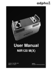
User Manual
NIR120 M – series
(Serial- No. >10240)
Version 3.0 (USA_UL)
6thAugust 2013
adphos
Innovation in thermal processing
Thank you for purchasing an adphos NIR drying system.
This manual will help to show the proper installation, operation and maintenance of
your NIR drying system and how it can be safely and efficiently operated with your
inkjet printing system.
NIR drying systems were developed with regard to the highest safety standards.
Proper installation, operation and maintenance of the system never places trained
operators or maintenance personnel at risk.
For your own safety and the safety of others, please read the following procedures in
this manual and follow all safety instructions.
adphos Innovative Technologies GmbH
Bruckmuehler Str. 27
83062 Bruckmuehl-Heufeld
Germany
Phone:
+49-8061-395-0
Fax:
+49-8061-395-395
Technically Trained Representation:
adphos North America, Inc.
3490 North 127th Street
Brookfield WI 53005
USA
[email protected]
Phone:
Fax:
Version 3.0
+1 (262) 790-9100
+1 (262) 790-1132
Page 2 of 35
!"#$
& '()*
,-./ 0) 1)2'*32)
4 5#)6* 2-6' # 7"#*'.)
8 9:; 2'<-'* -"=
>
?@ A
4 C)=)2' #
4& 9:; 5 -**)2
4 E" 3=* -=.
44 5#)6* 2-6' # 6"==)6* -"=
48 E"=-*"2-=. ( 3=6* -"=$
4% G"=* 2"# )#) )=*$
4+ :=6#-='* -"= $)=$"2
4D H"I)2 #)7)# $)#)6*"2
4F H3$/ !3**"=
4J K L -=*)2('6)
?@ MA
% 0'6/" )*)2 "1)2'* -"=
P Q N
O @ + C)=)2' #
+& R<S 3$* )=* 12"6)< 32)
B D G #)' =-=. "( 9:; ) -**)2
D & G #)' =-=. "( 9:; 2)( #)6*"2
D ;)1#'6) )=* "( 9:; 2)( #)6*"2T$U
D 4 E'-=*)=' =6) V-* T"1* -"=' #U
W
X@A A A F 9:;&J E ' =< 9:;&J E&
F & 9:;&J E
F 9:;&J E4
MA Y A@ @ @
[ Q
Z \
E)' =-=. "( * /) $*'*3$ ]5^_$
& 02" 3!#) $/""* -=. #-$*
Version 3.0
Page 3 of 35
%
+
+
+
+
B
D
D
F
8
%
&
&&
&
&
>
&8
&%
&%
N
&+
&D
J
&
&
&
4
8
Certificate of compliance
Version 3.0
Page 4 of 35
1. Indented use
The adphos NIR120 M-series drying systems were developed for complete and
secure drying of water-based and soft solvent non-flammable inks for continuous
and drop-on-demand inkjet systems.
It was designed for build-in use in commercial printing devices.
Warning
Fire hazard
The drying of hard solvent based flammable inks and the
use in hazard areas are not permitted with this adphos
NIR drying system configuration.
For solvent applications special available NIR systems are required!
Call +1 262-790-9100 (US) or +49-8061-395-0 (GER) for detailed information.
The standard mounting position of the NIR120 M(x) drying system is horizontal (see
chapter 3.3). As a result of the special design, the modules can be mounted in any
orientation parallel to the paper surface.
Depending on operating conditions, the NIR drying power of the module is adjustable
by varying the input signal and additionally the onboard power level selector.
2. NIR120 M - series
The NIR 120 M - series is available in four different versions.
They differ in the installed maximum NIR Emitter power and in the capability to
control the drying system via USB interface (see table 1).
The version is listed on the type plate at the backside of the dryer top.
Table 1: available NIR120 M versions
Version
Emitter power
class
Total power
(max.)
USB interface
adphos-no.
(module only)
NIR120 M1
LB-11/230V
3 kW
no
735 891
NIR120 M2
LB-11/230V
3 kW
yes
735 892
NIR120 M3
NB-21/230V
5,8 kW
yes
735 893
NIR120 M4
HB-31/230V
8,3 kW
yes
735 894
Version 3.0
Page 5 of 35
3. General safety instructions
3.1. Symbols
Different symbols are used in this user manual to point out potential risks during operation or maintenance of NIR drying modules.
Table 1 shows the symbols used and their meanings.
These symbols are also placed on appropriate parts of the drying system.
Please adhere to the safety instructions and procedures described in this manual.
Table 1: Symbols and their meanings
Symbol
Meaning
Attention!
Exclamation point: This symbol is used for safety notes.
Attention: hot surface, do not touch!
Every attempt has been made to keep all surfaces as cool as possible.
However, some surfaces such as emitters and reflectors can become
very hot so that serious burns can occur by touching these areas.
Attention: electrical voltage!
Only electrical trained personnel is allowed to work at current carrying
parts. Before starting work, the complete drying system has to be strictly
cut off from power and power cables have to be disconnected.
Attention: NIR radiation!
This sign indicates a possible hazard by NIR radiation during the drying
process.
Generally NIR radiation does not damage human tissue.
However, at close distances to the radiation source, burns to the skin can
occur.
Very close and direct view of the radiation source without eye protection
can cause damages to the eyes.
Version 3.0
Page 6 of 35
3.2. Safety
The adphos NIR drying systems are designed to be safe and effective when
operated according to the guidelines outlined in this user manual.
As with other industrial systems, there is a risk of personal injury if the products are
not used according to the guidelines outlined in this manual.
Warning: There is a risk of personal injury by improper use of this
equipment.
The following sections include information regarding operational safety for different
aspects of the dryer system.
Important: To ensure safe operation of this unit, personnel must
be trained regarding the proper use of this equipment.
Installation and operation of the system according to the
instructions as outlined in this user manual by properly trained
personal will avoid unforeseeable safety risks.
3.3. High Temperature
In spite of the cooling of the high temperature NIR emitters, the temperature of the reflector system and parts of the housing will exceed
49° C (120° F). Therefore do not touch the NIR drying module and
assembled parts during and within five minutes after operation.
3.4. Electrical voltage
NIR emitters operate at a voltage of 230 VAC.
Do not replace NIR emitters or attempt to repair drying systems with
electrical power running to the units.
Before replacing NIR emitters, opening the power cabinet or removing
any protection plates, make certain there is no electrical current
going to the power cabinet.
3.5. NIR radiation
NIR emitters send out an electromagnetic spectrum with a wavelength
around 1µm.
Because of the high yield of visible light during operation, do not look
directly into the radiation source without eye protection. Looking directly
at the radiation source may cause eye damage.
If direct exposure of the light to the eyes occurs, please seek medical attention
immediately.
For further protection wear class 4 protective goggles (optional, adphos no. 008857).
To minimize the NIR radiation to the surrounding area use optional light shield.
Version 3.0
Page 7 of 35
4. System description
4.1. General
The NIR120 M is a high power drying system with intelligent dryer control.
The module has a drying width of 4.7” (120mm) and a drying length of 9.8” (250mm).
Each module is 5.6” (143mm) wide x 14.6” (370mm) long x 9.5” (241mm) high.
It consists of the housing with the control/power unit, a high efficiency reflector and
three adphos NIR emitters.
The module is cooled by an internal fan and additionally monitored by a thermostat
and three temperature sensors.
An integrated onboard CPU supervises most drying functions, reacts to operating
situations and reports/indicates them to the user.
The USB interface allows updates, diagnostics, remote control, parameterization and
customizing of the NIR120 M2/3/4 drying systems.
An integrated inclination sensor senses the actual 3D position and reacts accordingly
to avoid an accidental switch-on of the drying system in a non-operating-position e.g.
during maintenance.
4.2. NIR Emitter
The NIR radiation is generated by a special NIR emitter, which includes a tungsten
filament, which is heated up to 3000K by an electrical voltage.
To increase the lifetime of the emitters, a small amount of halogen gas is added.
All materials used to manufacture the emitters are environmentally friendly.
Burned out or broken emitters can be disposed of as part of regular household
waste.
No special disposal is required.
The chemical compounds (tungsten-halides, deposition of tungsten at the quartz
glass), which may build up during improper use, are harmless in these
concentrations.
Injuries can occur through the breakage of the quartz glass tube.
Wear protection gloves and eye protection when handling broken emitters or glass
parts to avoid injuries.
Wear clean cotton gloves (optional adphos no. 403 166) when handling NIR emitters.
Greasy residues on the glass surface will reduce operation time dramatically.
Clean emitters with water and/or Isopropyl alcohol before inserting into module.
Note:
Use original adphos emitters only!
Use correctly specified emitter!
Each adphos emitter is labeled on the left-hand front side immediately after the 90°
bend.
The label shows the power class and charge number underneath the adphos logo.
e.g.: NIR LB-11/230V y1 ( 1100 W @ 230V production charge y1)
Version 3.0
Page 8 of 35
4.3. Mounting
Four fastening points with an M4 thread with screws are placed on the top side of the
NIR module (see figure 1). The distance between the threads is 4.13” (105mm).
Note:
Use original screws with a thread length of maximum 0.3” (8 mm) only to avoid
contact with built-in components!
The maximum torque to fasten the screws is 2 Nm (1.5 ft.lb)!
Figure 1: Fastening points on the upper side of the NIR120 M module
To ensure proper operation of the dryer, the distance between paper and bottom
edge of the module must be a minimum of 0.2” (5 mm).
Caution
Burn hazard
Due to NIR radiation the surface temperature opposite the
modules could exceed 120°F (49°C) .
Do not touch the surfaces during operation!
Ensure that no thermally sensitive devices are present in
the heating area.
For the drying of large scale papers, two NIR120 M can be mounted side by side.
Do not place the modules directly side by side, since this will result in cooling
problems. Instead, stagger them as shown in figure 2 for a proper cooling.
Version 3.0
Page 9 of 35
Figure 2: Two drying modules mounted side by side
4.3.1.
Fastening kit (included, adphos no.: 735 640)
To attach the NIR120 M on the mount arm (optional, adphos no.: 735305), a special
fastening kit is assembled.
The kit consists of two brackets with a sliding nut and a lock washer each.
Elongated holes in the brackets allow for adjusting of the mounting angle by up to 3°
between the arm and NIR120 M(x).
The fastening kit can be used to affix the module at the four fastening points
described in chapter 3.3 (see figure 3).
Call +1 262-790-9100 (US) or +49-8061-395-0 (GER) for detailed information.
Figure 3: mounting the fastening kit at the NIR120 M module
Version 3.0
Page 10 of 35
4.3.2.
Mount arm (optional, adphos no.: 735 305)
The optional mount arm is a modified Item-profile size 8, with a length of 870mm and
a frontal center thread M8/15mm (M8, 0.6” deep) on one side for the handle.
If needed, the arm can be cut to a customized length. Watch out for threaded side!
Call +1 262-790-9100 (US) or +49-8061-395-0 (GER) for detailed information.
4.3.3.
Light shield (optional, adphos no.: 735 294)
The optional available light shield is shown in fig. 6 and can be mounted at the base
of the NIR120 M drying modules to avoid a possible blinding of the operator by the
intensive light emission of the NIR-Emitter.
The physical dimensions of the light shield are 11.5” (292mm) in width x 20”
(507,5mm) in length.
To mount NIR120 M modules side by side, both shields on the side can be folded up
as shown in fig. 6
Figure 6: optional light shield
To mount the light shield on the lower edge of
the NIR120 M drying module, unscrew the
mounting screws on the long side until the
screws latch into the four supports of the shield
(see fig. 7). Then tighten the four screws
evenly with a maximum torque of 2 Nm (1.5
ft.lb).
Figure 7: fastening of the light shield on a NIR120 M module
Note:
If a customized light shield is used, the light shield
must not prevent the cooling air from exiting the
dryer module. This may cause overheating!
Call +1 262-790-9100 (US) or +49-8061-395-0 (GER) for detailed information.
Version 3.0
Page 11 of 35
4.3.4.
Mount (optional, adphos no.: 735 294)
The optional available mount is designed for a safe and quick on site positioning of
the NIR120 M with the mount arm (735305) .
The mount has a total height of 16.5” (419 mm) and a square base of 4.6” (117mm).
To fix the mount on the machine base four mounting holes with 0.33” (8,5mm) in
diameter are integrated in the square base.
Figure 4: mount
The mount consists of a tie bar (1) with a movable attachment (2) for the mount arm
(735305). The mount arm will be fixed to the attachment with four sliding nuts.
Cables will be fixed with cable ties at the 3 fixing points (4) on top of the arm.
To adjust the correct distance to the paper, the attachment can be adjusted over a
range of 2.4” (60 mm) in height with the crank handle (3) on the top of the tie bar.
To get easy access to the paper, the position of the module to the substrate can be
changed and fixed in three positions (see fig. 5). To do so the latching bolt (6) on the
side of the tie bar must be pulled and then the mount arm can be tilted by lifting the
handle (5) to the designated position (see fig. 5).
Call +1 262-790-9100 (US) or +49-8061-395-0 (GER) for detailed information.
Figure 5: operating and two maintenance positions of the mount
0° operating position
Version 3.0
45° maintenance position
Page 12 of 35
80° maintenance position
4.4. Electrical connection
Danger
Electric shock hazard
Only a certified electrician may connect the NIR120 M
system to the main electrical panel.
It is only allowed to terminate the NIR drying system to
mains specified on the type plate (max. voltage, current,
frequency)
4.4.1.
Main power supply
The NIR120 M drying modules are designed for use with 230 VAC 2-phase
50Hz/60Hz mains (1PE). Depending on the NIR dryer type, the following fuse rates
for external line breakers (both lines) are required (table 2):
Table 2:
Required voltages and fuse rates for the different NIR120 M versions
Version
Voltage
Fuse
rate
Phase
NIR120 M1
230 VAC (50 or 60Hz) ±10%
20 A
2-phase
NIR120 M2
230 VAC (50 or 60Hz) ±10%
20 A
2-phase
NIR120 M3
230 VAC (50 or 60Hz) ±10%
32 A
2-phase
NIR120 M4
230 VAC (50 or 60Hz) ±10%
40 A
2-phase
4.4.2.
Main power cord/cable
To order your customized main power cord, get in contact with:
adphos North America, Inc.,3490. North 127th Street, Brookfield WI 53005
The connection of the power cord to the NIR120 M module is carried out by a
Souriau UTS connector (3 Pin).
Note:
The module may only be connected to the main power supply by using a 3x 6
mm2 (AWG 10) UL approved cable.
National standards and regulations on ampacities must be observed!
Call +1 262-790-9100 (US) or +49-8061-395-0 (GER) for detailed information
Version 3.0
Page 13 of 35
4.4.3.
Main power connector
The main power connector is located on the left side of the upper edge of the
NIR120M module.
Figure 8: main connector of NIR120 M dying modules
pin assignment see fig. 9
Figure 9: pin assignment of Souriau UTS connector (plan view of the mounted male
connector)
Danger
Electric shock hazard
Before handling, connecting or disconnecting the Souriau
UTS connector (in case of service or maintenance) the
module must be switched off and physically
disconnected from the main electrical supply.
4.4.4.
Main power switch
The main power switch is located on the left side of the upper edge of the NIR120 M
module (see figure 8) and serves for connecting the power to the drying system. Two
conditions are available.
Table 3: Conditions of the main switch
Position
Condition
0
drying system off
1
drying system on
Version 3.0
Page 14 of 35
4.5. Monitoring functions
4.5.1.
Power supply monitoring
The controller of the NIR120 M drying module will permanently check the applied
power voltage.
If the power voltage is out of the specified range, the module will be locked and the
status LED of the analog input and output as well as the status LED near the push
button will be blinking red fast.
If this error occurs, check your main and connect the NIR120 M dryer to the correct
main power.
4.5.2.
Emitter power monitoring
NIR120 M dryers can be equipped with emitters of different power classes.
The installed power of the emitters must not exceed the total power of the dryer.
A permanent emitter power monitoring prevents damage to the NIR120 M1, NIR120
M2 and NIR120 M3 drying systems due to using NIR emitters out of the specified
range. If the system detects emitters with too much power, the dryer will be locked
and the LED near by the push button will blink green. This fault cannot be reset by
any function. You will need to shut down the system and install a correct NIR emitter
set.
4.5.3.
Input / Output control signal monitoring
An internal controller monitors the incoming and outgoing signal of the NIR120 M
dryer.
The majority of incorrect signals will be detected and signalized with the status LEDs.
(See troubleshooting).
•
•
•
•
Wrong polarity at input signal
Too high at input signal (voltage or resistance)
Too high current at output signal circuit
Voltage at Remote on/off
Notice
Three color LED combinations will inform the
user when incorrect signals are detected.
Damage cannot be ruled out.
Follow manual instructions for the control elements!
Version 3.0
Page 15 of 35
4.6. Control elements
All control elements of the NIR120 M drying modules are located on the top right of
the NIR120 M drying modules. The control elements include RCA connectors for
control voltage in- and output, an RCA connector for the remote I/O, a potentiometer,
a start push bottom and, finally, the USB plug socket.
There are also six multi-LED indicator lamps for indicating the module status.
An overview of the control elements is shown in fig. 11.
The connectors for the control voltage input and output and remote I/O are RCAconnectors (“RCA jack”)
Figure 11: control elements of the NIR120 M drying module
Status LED
control input
control input
Status LED
control voltage output
control voltage output
Status LED
remote I/O
remote I/O
Status LED
inclination sensor
power level selector
Status LED
power level selector
push button
Status LED
push button on/off
4.6.1.
USB interface
Input connector (white color)
Notice
Damage of the module by using input voltage
higher of 15 VDC or using AC voltage.
Use only a control voltage of less than 15 VDC.
In default configuration an external control input signal of 0-10 VDC (= 0-100%) is
required for operating the NIR120 M drying module.
The power of the emitters can also be aligned with the power level selector
(potentiometer).
To connect your external control voltage to the NIR120 M drying module, use a white
standard industrial RCA plug. The standard configuration of the RCA-plug is Pin1
(pin contact):+-wire and pin 2 (annular contact): –wire.
If the maximum external control voltage signal is higher than 10 VDC the status LED
near by the input connector will be blinking red fast.
Version 3.0
Page 16 of 35
Note:
At the output connector (red color) a constant voltage of 10 VDC is applied.
If external control voltage is not available, this constant control voltage output
of the module can be used for the input voltage signal.
Use a cable with two standard industrial RCA plugs and connect the control
input connector (white) to the internal output connector (red).
To adjust the power of the dryer dependent upon print speed, an external control
voltage from a tachometer or other device can be also applied.
Table 4: meanings of status LED control voltage input
Status
Meaning
Blinking red, fast
Supply voltage or input voltage are out of range
Red
Input value is less than 1%
Green
Input value is greater than or equal to 1%
Version 3.0
Page 17 of 35
4.6.2.
Control voltage output connector (red color)
The control voltage output is a voltage signal. Use a minimum resistance of 10kOhm.
At the control voltage output connector a constant voltage of 10 VDC is applied.
Note for model NIR120 M2, NIR120 M3, NIR120 M4:
These models can be configured via USB.
Option to be configured:
• Power relation to output signal e.g. 0-10V DC = 0-100% power
Call +1 262-790-9100 (US) or +49-8061-395-0 (GER) for detailed information.
Notice
Damage of the module by connecting an
input voltage.
Never connect input voltage to the control voltage out
connector.
To use the external control voltage from the control voltage out connector of the
NIR120 M drying module use a red standard industrial RCA plug.
The standard configuration of the RCA-plug is Pin1 (pin contact):+-wire and pin 2
(annular contact): –wire.
Table 6: meanings of status LED control voltage output
Status
Meaning
Blinking red, fast
Supply voltage or output voltage are out of range
Red
Output value is less than 1%
Green
Output value is greater than or equal to 1%
Version 3.0
Page 18 of 35
4.6.3.
Remote I/O (yellow color)
Caution
Fire hazard
Do not use the NIR120 M module with a jumpered Remote
I/O. In case of an unforeseen belt or paper stop, the NIR
module will not shut down.
Notice
Damage of the module by using a control
voltage for the Remote I/O.
Connect the Remote I/O only to a non-potential contact in
the machine control.
Link the Remote I/O signal with your paper/web transport, so that Remote I/O signal
is active only during working paper/web transport.
By using the Remote I/O the NIR emitters can be switched on and off by an external
control signal from a conveyor system, mailerbase or web system.
The Remote I/O requires a potential-free (dry contact) only!
For operation of the emitters, the remote I/O contact must be closed.
Do not attach AC or DC voltage directly to remote I/O (use Interface box Remote I/O)
Table 7: meanings of status LED Remote I/O
Status
Meaning
Red
Unlocked, contact open
Green
Locked, contact closed
Version 3.0
Page 19 of 35
4.6.3.1.
Interface-Box Remote I/O (optional adphos- no.:736022)
If a potential-free contact (dry contact) is not available in the machine control, a
control voltage can be used in combination with the Interface-box Remote I/O (see
figure 12).
The optional Interface-box Remote I/O consists of an electronic relay for control
voltages in a range of 24N.120 VDC/VAC.
The relay is integrated in a plastic box.
A 16 feet (4.9 m) long 2x 0,75 mm2 (AWG 19) cable with cable end sleeves is
available to connect the relay to the machine control.
A 4.5 feed (1.4 m) long coaxial cable with a yellow RCA connector is provided as a
connection to the NIR120 M drying module.
Figure 12: optional Interface-box Remote I/O
Danger
Electric shock hazard
Only a certified electrician may connect electric voltages in a
range of 24N.120 VDC/VAC
Version 3.0
Page 20 of 35
4.7. Inclination sensor
An inclination sensor on the control board of the NIR120 M drying module watches
the operating position of the module (default configuration horizontal alignment).
If the positional deviates more than ~10° from the horizontal, the module will be
locked. The status LED turns red and the push button status LED will blink red.
To unlock put the device in the operating position and push the push button (both
status LEDs will turn green).
Note for NIR120 M2, NIR120 M3, NIR120 M4:
These models can be configured via USB.
Option to be configured:
• Operating position
• Tolerance of inclination angle
Call +1 262-790-9100 (US) or +49-8061-395-0 (GER) for detailed information.
Table 8: meanings of status LED Inclination sensor
Status
Meaning
Blinking red, fast
Signal from sensor is invalid (e.g. not calibrated)
Red
Out of operating position, module ready
Green
In operating position, module is ready or running
Version 3.0
Page 21 of 35
4.8. Power level selector
The power level selector is a potentiometer located below the Remote I/O connector
(see figure 11).
By rotating the knob of the potentiometer, the power of the drying system will be
adjusted.
The effect of adjustment depends on the kind of external control voltage (default).
If a constant external power control of 10 VDC is used, the power of the NIR dryer
continuously varies between 0% and 100% of the possible drying power (default).
If a variable external control device (e.g., tachometer signal) is used, the
potentiometer is used to tune the power for the external control voltage for the drying
power. Detailed information can be found in chapter 3.5.1. Optimal adjustment of the
dryer is described in chapter 7.
Note for NIR120 M2, NIR120 M3, NIR120 M4:
These models can be configured via USB.
Option to be configured:
• Enable /disable
• Function
Call +1 262-790-9100 (US) or +49-8061-395-0 (GER) for detailed information.
Table 9: meanings of the different indicators for the power level selector
Status
Meaning
Off
Potentiometer disabled
Red
Value is less than 1%
Green
Value is greater than or equal to 1%
Version 3.0
Page 22 of 35
4.9. Push button
The push button is located below the power level selector (see figure 11).
The push button will be used to unlock the NIR120 M dryer after any system error.
It can also be used by the operator to lock the operating NIR120 M dryer manually
(remote I/O closed). To restart the dryer, push the button again (remote I/O closed).
Note for NIR120 M2, NIR120 M3, NIR120 M4:
These models can be configured via USB.
Option to be configured:
• Enable/disable
• function
Call +1 262-790-9100 (US) or +49-8061-395-0 (GER) for detailed information.
Table 10: meanings of the different indicators for the power level selector
Status LED pushbutton
red
device is ready and is waiting for a start signal
green
a start signal has been detected and the device is running now (the
requested power may still be 0%)
blinking red vs.
green
device is not ready, an error condition remains
blinking red
device is initializing
blinking green
device is suspended; the button must be pressed to resume the
device
yellow
temperature error (temperature switch set)
blinking yellow vs.
green
temperature threshold reached (IRS / environment 40°C, IRL CPU
65°C, IRL controller 85°C)
blinking green fast
one or several emitters are not working (power too low or too high)
blinking red, fast
device is locked (an error occurred while the device was running or
has been suspended); the pushbutton must be pressed to unlock
the device
4.10. USB interface
The internal USB-interface is only installed in the NIR120 M2, NIR120 M3 and
NIR120 M4 version and will be used for parameterization and customizing the
accordingly NIR120 M drying system.
Call +1 262-790-9100 (US) or +49-8061-395-0 (GER) for detailed information.
Version 3.0
Page 23 of 35
5. System installation
Important:
During operation of the drying systems, significant heat will be produced in the
proximity of the dryer module. The installation location of the dryer module
must be selected in such a way, that no damage will be caused to the
production line or objects in the surrounding area by the thermal effects of the
drying system(s).
When mounting the dryer module on a web transport, make sure no components
may be damaged by the thermal effects both beneath and to the sides of the web.
When mounting the dryer module on a sheet-feed transport, make sure to use "hightemp" transport belts, and ensure that the “top deck” of the transport is suitable for
high temperatures.
Danger
Electric shock hazard
Installation of NIR drying systems to be performed by
trained personnel only. Only a qualified electrician may
connect the module to the main.
1.
2.
3.
4.
5.
Remove packaging and check that the contents are complete and undamaged.
Check proper position of all three inserted emitters
Attach the light shield at the module (optional).
Check proper torque of all screws that are accessible from outside the module.
Mount the NIR dryer module on the line. Make sure that the dryer module is
parallel to the paper in a horizontal position and the distance to the paper surface
complies with the specifications.
6. Mount the tachometer on the line according to the manual (optional).
7. Wire all cables as described in sections 3.4 and 3.5.
(Input signal / Output signal / Remote I/O signal)
8. Double check Remote I/O function (safety related function).
9. Make sure the main power switch is in the “Off” position.
10. Set the power level selector to the “0” position (turn left as far as it will go).
11. Plug the power cable into the NIR120 M before connecting the cable to the mains.
Mains line breakers must be open for connection
12. Close breakers to power mains connection.
13. Switch the main power switch to “1” position (on). The cooling fans in the dryer
module will turn on.
14. Self-test-procedure of status LEDs.
15. Turn on the mailbase or web transport thus supplying the proper Remote I/O
signal to the NIR120 M drying module and allowing operation of the NIR emitters.
16. Be sure that a proper control voltage is applied correctly at the input control
voltage connector.
17. Slowly turn the power level selector clockwise until a glowing light is visible under
the NIR dryer module. Raising the power the visible light will turn from orange
“glowing” up to bright white shinning at 100% power.
Version 3.0
Page 24 of 35
6. Operation
6.1. Tachometer operation
As described above, the NIR dryer system can operate with an external control
voltage. To control the drying system proportional to the paper speed in an open loop
control, a control voltage in the range of 0 VDC and 10 VDC must be available.
If the control voltage is not available from the central controlling system (now base or
web transport) an external tachometer must be mounted (e.g. on a roller or
conveyor).
Optional adphos tacho´s
Speed
m/min
75
100
150
ft/min
246
328
492
Version 3.0
adphos- item
Adphos-No.
Tachometerkit 75 m/min
Tachometerkit 100 m/min
Tachometerkit 150 m/min
557153
557155
557156
Page 25 of 35
“
7. Adjustment of the dryer
7.1. General
Turn the power level selector and the main switch to the “0” position, to avoid any
damages of the paper. Be sure that the module is mounted to the mailerbase or
paper feeder properly.
7.2. Adjustment procedure
After successful installation the next step is to adjust the degree of dryness.
Therefore follow the next instructions step by step.
1. Switch the main power switch to “1”position (on), the cooling fans in the dryer
module will turn on. Additionally all Status LED’s are blinking red one after the
other for a short time.
2. Turn on the mailbase or web transport thus supplying the proper control voltage to
the NIR120 M module and allowing operation of the NIR emitters.
3. Slowly turn the power level selector clockwise until a steady glowing light is visible
under the NIR dryer module.
4. Start the inkjet printing system printing and make test prints at the desired running
speed.
5. Rotate the power level selector clockwise until the test prints reach the optimal
drying quality.
Call +1 262-790-9100 (US) or +49-8061-395-0 (GER) for detailed information.
Version 3.0
Page 26 of 35
8. Maintenance
Danger
Electric shock hazard
Maintenance of electrical components to be performed
only by trained electricians.
Before disconnect the mains connector at the NIR120 M
(in case of handling or maintenance), the module must be
switched off and physically disconnected from the main.
adphos NIR drying systems are designed to require minimal maintenance. The
following components as described in table 11 should be checked according to the
specified service interval.
Table. 11: Service intervals of components NIR dryer system.
No.
Component
Interval
Description
1
Error / alarm condition
daily
Check status LED´s during
operation
2
Reflector of the NIR dryer
module
2 weeks
Visually inspect the reflector for
dust, dirt and damage
3
NIR emitter
Monthly
Visually inspect the emitter(s) for
dust, dirt and damage
4
Wiring
Monthly
Visually inspect all wires and cables
for damage
8.1. Cleaning of NIR emitter
For cleaning the NIR emitter follow the instructions below step by step:
Before cleaning remove the dryer module(s) and place on a
soft pad to avoid damage.
NIR emitters are only be touched or handled with
protective clean cotton gloves. Sebaceous residues on the
glass surface will reduce operation time dramatically. Before
cleaning the emitters remove them out of the dryer module.
To remove the emitters out of the dryer module, with cotton
gloves, gently grab the emitter on both ends by the 90 degree
bend in the emitter and pull the emitter straight out of the
dryer module. Avoid touching of the emitter contact to the
reflector (optional emitter extraction tool adphos part number
726 174).
Version 3.0
Page 27 of 35
Light contamination can be removed with water and/or
Isopropyl alcohol. Persistent contamination can be removed
with a gentle polishing paste (see opposite figure).
If after cleaning the quartz glass bulb is still cloudy or
damage is visible (specifically by the contact area) the
emitter should be replaced.
To reinstall the emitters be sure that the connecting contacts
at the ends of emitters are straight and not bent (straighten
them if bent). Insert the clean NIR emitter into reflector by
taking the emitter in both hands (wearing protective cotton
gloves!) and plug the contacts completely into the jackets of
both ends of the reflector until the contacts are securely in
place (be sure not to force or jam the contacts into the
jackets!).
Important:
New emitters should always be cleaned with alcohol to remove any possible
contaminants which may have been deposited during the manufacturing,
shipment and storage of the emitters.
8.2. Cleaning of NIR reflector
Danger
Electric shock hazard
Maintenance of electrical components to be performed
only by trained electricians.
Before disconnect the NIR20 M main connector (in case
of handling or maintenance) the module must be
switched off and physically disconnected from the main.
Note!
Before cleaning remove the dryer module(s) and place on a soft
pad to avoid damage. Remove NIR emitter first! (see chapter 7.1)
Note!
Avoid any flow or contamination of water or cleaning agents into
the module. A damage of the module will occur.
NIR reflectors are manufactured out of specially coated aluminum sheets.
Contamination of the reflectors results in a reduction of reflectivity which under
certain circumstances can damage the reflectors or cause over temperature
emergency stop.
Version 3.0
Page 28 of 35
Clean NIR reflectors only with a slightly damp micro fiber cloth (see fig. 13) to prevent
any damages on the electrical components of the module.
Figure 13: cleaning of NIR reflector by slightly damp micro fiber cloth.
Generally, for each NIR reflector a clean, soft und lint-free cleaning tissue, e.g. cotton
tissue, should be used.
Do not apply force during cleaning and do not try to remove insistent contaminations
by using sharp objects as damage to the reflector surface will occur.
Version 3.0
Page 29 of 35
8.3. Replacement of NIR reflector(s)
Danger
Electric shock hazard
Maintenance of electrical components to be performed
only by trained electricians.
Before disconnect the Souriau UTS connector (in case of
handling or maintenance ) the module must be switched
off and physically disconnected from the main.
Note!
Before cleaning remove the dryer module(s) and place on a soft
pad to avoid damage. Remove NIR emitter first! (see chapter 7.1)
If contaminations cannot get removed from the surface, the reflector must be
replaced.
Therefore follow the instructions below step by step
The reflector is fixed on the module by 4 screws inside the
NIR120 M drying module. The access is carried out by 4
holes in both long sides exterior plates (see opposite fig.).
To bold the screws use a Phillips recessed head screwdriver
(size PHX). Turn the screwdriver counter-clockwise and
unscrew the screws up to the stop.
The opposite figures shows
the position of the screws
tighten (a) and bold (b)
(a)
Version 3.0
Page 30 of 35
(b)
Extract the reflector assembly upward.
The reflector assembly is connected with three wires, a
green-yellow grounding wire and two brown wires for the
thermo-switch to the control unit.
First strip the ground cable
from the contact tab at the
edge the long side plate (a).
Then strip both cables from
the thermo switch in the
middle of the reflector unit
(b). Now the reflector unit
can be replaced with a new
one.
(a)
The assembly of the module
with the new reflector will be
carried out in the reverse
order. Make sure that the
edges of the module
housing(see arrows in c)) are
completely fitted in the
framed notch of the reflector
assembly (d).
(c)
(b)
(d)
Finally tighten the four screws as described above.
8.4. Maintenance kit (optional)
Required tools and materials (except liquid solvents and micro fiber cloth) are
arranged in an optional maintenance kit, adphos-no. 712 373.
Call +1 262-790-9100 (US) or +49-8061-395-0 (GER) for detailed information.
Version 3.0
Page 31 of 35
9. Component and spare part list
9.1. NIR120 M1 and NIR120 M2
Description
Quantity
adphosorder-no.
Parts list
position
NIR120 M1 - drying module (without NIR
emitters)
1
735 891
NIR120 M2 - drying module (without NIR
emitters)
1
735 892
Light Weight Reflector (LWR),
complete for NIR120 M1 or NIR120 M2
1
735 353
1
NIR Emitter LB-11/230V (1.1kW)
3
735 679
2
Quantity
adphosorder-no.
Parts list
position
1
735 893
1
736 142
1
NIR Emitter LB-11/230V (1.1kW)
3
735 679
2
NIR Emitter NB-21/230V (2.1kW)
3
735 677
2
Quantity
adphosorder-no.
Parts list
position
1
735 894
1
736 143
1
NIR Emitter LB-11/230V (1.1kW)
3
735 679
2
NIR Emitter NB-21/230V (2.1kW)
3
735 677
2
NIR Emitter HB-31/230V (3.1kW)
3
735 263
2
9.2. NIR120 M3
Description
NIR120 M3 - drying module (without NIR
emitters)
Light Weight Reflector (LWR),
complete for NIR120 M3
9.3. NIR120 M4
Description
NIR120 M43 - drying module (without NIR
emitters)
Light Weight Reflector (LWR),
complete for NIR120 M4
Version 3.0
Page 32 of 35
10. Optional equipment and maintenance material
Description
Quantity
adphos
order-no.
NIR protective goggles
1
408 857
NIR emitter removal tool
1
726 174
1 package
403 166
1
712 373
Maintenance materials / Option
cotton gloves
Complete maintenance set in a case , includes
- NIR protective goggles
- Emitter removal tool
- Cotton gloves
- Cleaning paste for NIR emitters
11. Troubleshooting
Danger
Electric shock hazard
Maintenance of electrical components to be performed
only by trained electricians.
Before disconnecting the Souriau UTS connector (in case
of handling or maintenance) the module must be
switched off and physically disconnected from the main.
If issues cannot be solved by using the troubleshooting matrix described below, call
the central adphos service point (phone +49-8061-395-0 or +1 262-790-9100)
Version 3.0
Page 33 of 35
11.1. Meaning of the status LED´s
Status LED analogue input
off
analogue input is disabled
blinking red, fast
input signal is out of range
red
input value is less than 1%
green
input value is greater or equal than 1%
Status LED analogue output
off
analogue output is disabled
blinking red, fast
supply voltage or output voltage are out of range
red
output value is less than 1%
green
output value is greater or equal than 1%
Status LED remote on/off input
off
remote on/off input is disabled
red
Unlocked, contact open
green
Locked, contact closed
Status LED inclination sensor
off
Inclination sensor is disabled
blinking red, fast
signal from inclination sensor is invalid (e.g. not calibrated)
red
out of operating position
green
in operating position
Status LED power level selector
off
Power level selector is disabled
red
value is less than 1%
green
value is greater or equal than 1%
Status LED pushbutton
red
device is ready and is waiting for a start signal
green
a start signal has been detected and the device is running now (the
requested power still may be 0%)
blinking red vs.
device is not ready, an error condition holds
green
blinking red
device is initialising
blinking green
device is suspended; the button must be pressed to resume the
device
yellow
temperature error (temperature switch set)
blinking yellow vs.
temperature threshold reached (IRS / environment 40°C, IRL CPU
green
65°C, IRL controller 85°C)
blinking green fast
one or several emitters are not working (power too low or too high)
blinking red, fast
device is locked (an error occurred while the device was running or
has been suspended); the pushbutton must be pressed to unlock
the device
Version 3.0
Page 34 of 35
11.2. Trouble shooting list
Failure
NIR emitter doesn’t work
Cause
Module not connect with main
Display status LED
-
Main switch in “0“ position (off)
Main power out of range
Power level selector “0” position
AI : blinking red fast
AO2): blinking red fast
Pi3): red
Pb4): blinking red fast
IO5): red
AI1): red
AO2): red
AI1): blinking red fast
AO2): red
Pb4): blinking red fast
Ps6): red
Temperature switch set
Pb4): yellow
Internal temperature threshold
reached
Pb4): blinking yellow vs.
green
Installed emitters out of the allowed
range
Pb4): blinking green
1)
Module not in horizontal position
Remote I/O contact open
Control voltage too low
Control voltage more the 11VDC
NIR emitters work but shut
down after a present time
1)
AI = Analog input
AO = Analog output
2)
Pi3)
= Inclination sensor
4)
Pb : = Push button
IO5)
Ps6)
Page 35 of 35
Action
First plug Souriau connector into socket
second connect power cable to main
Set main switch to “1” position (on)
Check the main source
Set module in horizontal position
Press push button to unlocked the dryer
Check the Remote I/O signal
Check the control voltage, dryer will start at
a control voltage ≥ 100 mV DC
Check the control voltage; control voltage
max. 10 VDC.
Press push button to unlocked the dryer
Turn the knob clockwise until the emitter work
correctly
Check the position of the module regarding
accessibility cooling air, check the reflector
regarding pollution.
Check the position of the module regarding
accessibility cooling air and environmental
temperature
Install the correct emitter types
= Remote I/O
= Power level selector