1
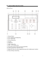
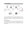
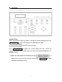
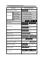
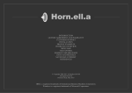
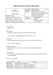
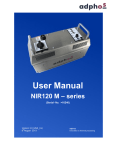
CCTV CONTROL KEYBOARD Contents ▓ Features 2 ▓ Specification 3 ▓ Front and Back Panel Description 4 ▓ System Installation 6 ▓ Operation 7 ▓ Simple Operational Reference Table 14 ▓ Accessory 15 2004/09/13, Ver.: 1.1, P/N: 040075 1 ▓ Features Support CCTV system control. Control Dome Camera and P/T/Z Receivers with RS-485 Interface. Supports up to a total of 127 devices (127 Dome Camera or P/T/Z Receiver.) The 3-axis joystick supports Pan/Tilt control and Auto Focus function. 2 ▓ Specification Power DC 12V Power Consumption 2W Control signal RS-485 Standard 9600 Baud Rate Control Device 127 Devices Manual Pan/Tilt Control Auto Lens Control Camera Control Pan Right / Left Tilt Up / Down Pan On / Off Sequence On / Off ZOOM Tele / Wide FOCUS Near / Far / Auto BRIGHTNESS +/- Preset Point 128 Camera Setup Available Dimension 296x190.4x52.7mm ( W x D x H ) O.P Temperature 0°~45°C Weight 1.4 Kg Symbol Description 1. Function keys are shown by, framed capital boldface print letters. Example: ENTER , AUTO FOCUS , etc. 2. Function key “+” indicates the order sequence. Example: 2 8 + ENTER meaning, press the function key “ 2 “, ” 8 ”, and then ENTER . DEVICE 001 : _ 3. ; indicate messages from the device and is shown on the control keyboard LCD display. 4. “n” indicates the ID number of the nth device (ID numbers ranges from 001~127). 3 ▓ Front and Back Panel Description ►Front Panel ① ② ③ ④ ⑤ System Reset ESC, ENTER and Number Key Lens Control Key Device Select Key Joystick ⑥ LCD Panel ⑦ OSD Function Key ⑧ OSD / LCD Function Keys ⑨ ⑩ ⑪ ⑫ Preset Key (Preset setup or run preset position) Auto Key (Auto-Pan and Auto-Focus) Speed By Zoom Key (Auto speed adjustment with multiple zoom function) External Relay Control Key 4 ►Back Panel ① Power in connector ( DC 12V ) ② RS-485 connector ③ RS-485 RJ-11 connector 5 Pin No. Definition 1 - 2 - 3 - 4 D+ 5 D- 6 - ▓ System Installation Fig 1.1 The system supports connections of numerous Speed Dome Cameras or P/T/Z Receivers, assigning a set ID (Note! ID numbers ranges from 1~127 and may not be repeated) for setup and control, through control keyboard (Ref. Fig 1.1). ►Connecting RS-485 Connect RS-485 terminal D+ from the control keyboard to terminal D+ of RS-485 DATA IN connector from the device; then connect RS-485 terminal D(the same set of terminal) to the terminal D- of RS-485 DATA IN connector from the device. 6 ▓ Operation System Reset After connecting all necessary cables, startup the system linking by pressing SYS RESET key. The LCD displays the following message: SYSTEM LINKING? (the LED starts flashing). Press SYS RESET key again, the system linking will start, search the system connection device and make sure that all the connected devices are probably linked. * When the LCD displays the following message: DEVICE : XXX LOST , it PRESS SYS RESET means that an error has been occurred. Please press checking and sorting the circuit. 7 SYS RESET key, after Manual Control (Up / Down / Left / Right / Speed) Speed Dome Cameras or P/T/Z Receivers may be controlled manually, by using the joystick (Up / Down / Left / Right / Speed). ►Joystick The movement depends on the angel of the joystick: Push the joystick up or down, the device will move forward or backward. Push the joystick left or right, the device moves leftward or rightward. ►Zoom Speed Setup The LED lights up after pressing SPEED BY ZOOM key. Then, the Pan / Tilt movement of the Dome will be proportional to each ratio. * Movement slows down when zooming. Device Select Key ►Use the number key + ENTER key Pre-select the desired nth device, by pressing the number and ENTER Key on the controller keyboard. Then, the LCD will display ID of the device. ►Use the DOME SELECT KEY function of control keyboard. DOME SELECT Key DOME SELECT ( CH+ ) the system automatically selects for the ID number larger than the present ID number. DOME SELECT ( CH- ) the system automatically selects for the ID number smaller than the present ID number. * After completing the change, the LCD will reflect the selected device ID and when the action was failed or the selected device did not exist, no changes will be shown by the LCD, it remains as original status. 8 Zoom Control This item allows you to change the zoom ration from OFF to 220X (22 times optical magnify). ►Lens Control-Zoom TELE Press ZOOM TELE key to stop zooming. key, to narrow the angle of viewing and release the ►Lens Control-Zoom WIDE Press ZOOM WIDE to stop zooming. key, to widen the angle of viewing and release the key Focus Control Focus Control may be done by AUTO or manually by the user. ►Manual Control- Focus Far Press FOCUS FAR key, to focus far and release the key to stop focusing. ►Manual Control- Focus Near Press FOCUS NEAR focusing. key, to focus near and release the key to stop ►Auto Focus Control Press AUTO FOCUS AUTO FOCUS the function. * FOCUS FAR key or the joystick, the LED of the lights up and press and FOCUS NEAR AUTO FOCUS key again, to disable will not function, when AUTO FOCUS function has been started. 9 Setting the Preset Points Setting the preset point enables the Speed Dome Camera to have preset points from 1~128. You may key in a number (1~128) and press SET PRESET key, to store current position as preset. You may also key in a number and run the preset point that you’ve just stored. ① Selecting a Speed Dome Camera Press 1 key and the ENTER key, the LCD will display: DEVICE 001 : _ , it means that Speed Dome number “1” has been selected. Example: Select the 1st Speed dome Camera = 1 + ENTER Select the 127th Speed dome Camera = 1 2 7 + ENTER ① Controlling the Joystick The joystick may move the Speed Dome to that specific location. ① Controlling the zoom ratio from 1X to 220X (22 times optical). It is suggested when setting the preset points to manually adjust the iris, to enable clarity and stability of the focal distance. ① Key in a number (1~128) and press SET PRESET key, the LCD will SAVE TO PRESET , then press again SET PRESET key, XXX ? SAVE OK! and when the display show: , meaning that the setup has display: been completed. * Repeat the steps 1~4 again, to set more preset points. 10 Call upon the Preset Points When the setup of the preset point has been completed, it may be called upon. ►Enter the assigned preset number and press GO PRESET key, the LCD GO PRESET : XXX will display: ,and the Speed Dome will move to that specific preset point. Example: 1st preset point = 1 + GO PRESET 128th preset point = 1 2 8 + GO PRESET Change the Preset Point To change the preset point, use the joystick to move the cursor to the preset point setup selection and change to your desired settings. AUTO PAN The function has numerous groups (every group has numerous setting points) and you have to decide the pan direction and the pan speed for each point. ►Start-up Auto Pan Mode Under Control Mode (assume device=1), when the LCD displays: DEVICE 001 : _ , key in the group number to be setup (Assume group=1, then enter 1), then press AUTO PAN key, the LED of the AUTO DEVICE 001 : PAN lights up , LCD displays , meaning that the AUTOPAN GROUP : 1 setup has been completed. ►Stop Auto Pan Mode Press AUTO PAN key or move joystick, the LED of the AUTO PAN goes off, meaning that the function has been disabled (Please refer to P.8). ►About Auto Pan Mode When Auto Pan Mode has been started, no other operations will function. Unless, when Auto Pan Mode has been disabled. 11 Relay Control Three sets of relay control are provided: RELAY1, RELAY2 and RELAY3, (when using P/T/Z Receiver.) ►Relay ON The RELAY1 LED lights up when RELAY1 key has been pressed. That means RELAY1 is set ON and the output has been connected (close status). ►Relay OFF The RELAY1 LED will not light up when RELAY1 key has been pressed. That means RELAY1 is set OFF and the output has been disconnected (open status). Alarm Management ►Alarm Input The Speed Dome Camera is equipped with six alarm input connectors, Alarm 1~Alarm 6, corresponds to both preset points and AUTO PAN Group. Once the alarm signal is detected, the Speed Dome Camera will automatically move to the preset point or Start-up AUTO PAN. ►Alarm Management of P/T/Z Receiver or devices, please refer to the relevant guide. ►Alarm Mode Management The Speed Dome Camera is set to lock on the last alarm input. Thus, once the alarm signal is detected, the Speed Dome Camera will automatically move to the preset point or Start-up AUTO PAN, triggering the alarm to buzz, EVENT RESET LED will be lighted and the LCD will display: DEVICE : XXX ALARM INPUT , informing the user that an alarm event has been detected. The buzzer does not dismiss automatically, the user has to press the EVENT RESET key in order to stop the buzzer. When the alarm of more than one device has been triggered continuously, than the system select to lock on controlling the last device triggered by alarm event. 12 ● When the alarm of the Speed Dome Camera has been triggered under Auto Pan ON mode, the Speed Dome Camera will rotate in 300° per second to the preset correspondent point (AUTO PAN Group). When the alarm of more than one device has been triggered continuously, than the system select to lock on controlling the last device triggered by alarm event. ● When the alarm of the Speed Dome Camera has been triggered under Auto Pan OFF mode, the Speed Dome Camera will rotate in 300° per second to the preset correspondent point (AUTO PAN Group). 13 ▓ Simple Operational Reference Table Functions Restart System Connection Method of Operation SYS RESET ON) (SYS RESET LED Upward rotation Push the joystick forward Downward rotation Push the joystick backward Leftward rotation Push the joystick leftward Rightward rotation Push the joystick rightward P/T/Z Control Select Dome Camera Lens Control No. Key+ ENTER ZOOM TELE or or CH+ 、 CH- ZOOM WIDE FOCUS FAR (AUTO FOCUS LED OFF) Manual Control FOCUS NEAR (AUTO FOCUS LED OFF) Auto Focus AUTO FOCUS (AUTO FOCUS LED ON) Speed By Zoom SPEED BY ZOOM (SPEED BY ZOOM LED ON) Brightness Control BRIGHTNESS + Chose to Select the Preset Points No. Key + GO PRESET (128 Preset Points) Start-up the Preset Mode No. Key (Group No.)+ AUTO PAN (AUTO PAN LED ON) Stop the Preset Mode AUTO PAN or Push the joystick (AUTO PAN LED OFF) Disable the Alarm EVENT RESET (EVENT RESET LED OFF) Relay Switch RELAY1 RELAY2 RELAY3 (LED light ON meaning LED ON and vise versa.) 14 or BRIGHTNESS - . ▓ Accessories 1. Power Adaptor (DC 12V) 2. User’s Manual 15