1
4 Operating
4.3.2
4.3 The windows and menus
Lenord + Bauer
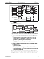
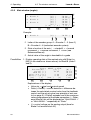
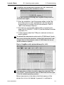
Main window (angles)
01/01
1. Blade 1:
MAIN WINDOW
[A] |
[B] |
[A] |
[B] |
[A] |
[B] |
[I/O]
[ U ]
2. Blade 2:
3. Blade 3:
F1
F2
F3
F4
MENU
78.54° *
78.54° ÿ|
78.53° |
78.53° |
78.54° |
78.54° |
[ D ]
M1
M2
M3
M4
F5
Example:
2. Blade 2:
[A] |
78.53° |
c d
e
c Letter of the encoder group: A = Encoder 1…3 (here 2),
B = Encoder 4…6 (redundant encoder system)
d State of motion of the axis: | = standstill, > = forward
movement, < = reverse movement, E = error (see
Reference Manual)
e Actual value of the angle in hundredth of a grade
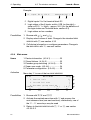
Possibilities
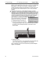
1. Display operating data of the marked axis with [Enter] or
[M3] (in the window as shown above) for Blade 2 (Axes 2
and 4):
OPERATING STATE: BLADE 2
State: RESET + STOP
Encoder/Dir.:
[A] |
Actual [°]:
78.53
Nominal [°]:
Veloc.a/n [°/s]:
0.00
Delta [°]/U [V]:
0.00
[<<]
[<]
[CAL.]
[>]
F1
F2
F3
F4
BACK M1
[B] |
78.53
78.54
0.00
0.000
[>>]
M2
M3
M4
F5
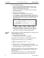
Explanations of the display:
• Veloc.a/n = actual and nominal speed
• Delta (= DeltaS) = control deviation = difference between the calculated nominal value from the feedback
control and the actual value (see principle of axis control on page 5); if DeltaS exceeds one of the maximum
values programmed at the blade parameters ( → Reference Manual) this will be displayed as "DRAG ERROR +"
or "DRAG ERROR -" respectively at "State:"
• U = control voltage on the analog output (here for
Blade 2 at terminal block A2)
20
DS12-8230Y5B10