1
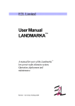
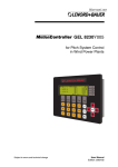
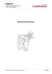
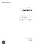
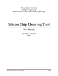
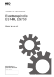
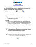
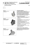
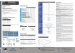
MotionController GEL 823x LENORD +BAUER with integrated PLC functionality ... automates motion. Technical Information Version 06.12 General information MotionControllers of the serie GEL 823x are optimised for the rough environment of rotor hubs in wind turbines. The MotionController is a compact controller with CPU, LC display, key board, integrated PLC, fieldbus systems and multi axis control with a maximum of 6 controlled axes. A total of up to 64 axes can be controlled via the CAN bus (6 axes with feedback). Additional inputs and outputs permit serveral CAN REMOTE I/Os with up to 64 inputs or outputs per node and up to 64 node addresses. Hardware RAM: 1 MByte in total NVRAM: 8 kByte in total Flash: 1 MByte in total Free memory space: 256 kByte Advantages Robust controller for up to 6 axes, not affected by shock and vibrations Extended temperature range -20 °C to +70 °C Open to all standard fieldbus systems High noise immunity due to galvanically isolated digitial and analogue inputs and outputs Short projecting times due to ready-made functional blocks and pre-configured inputs and outputs Field of application Features GEL 8230 GEL 8231 GEL 8232 Digital inputs 22 30 30 Digital outputs 15 15 15 Analogue inputs 1 3 3 PT100 inputs 0 4 4 Analogue outputs 3 3 3 Coated electronics yes yes no TACTILE PRESSURE EXPERTS -823x Wind energy (onshore, nearshore, offshore) Harsh industrial environments SENSOR PRODUCTS INC. Sensor Products Inc. 300 Madison Avenue Madison, NJ 07940 USA Phone: 1.973.884.1755 Fax: 1.973.884.1699 [email protected] Internet: www.lenord.de www.sensorprod.com Sensor Products, Inc. is a certified distributor for Lenord + Bauer in the U.S.A. ©2014 Sensor Products Inc. Phone: +49 208 9963–0 Lenord, Bauer & Co. GmbH Updated 8-26-2014 Description Construction and design Programming The MotionController are delivered with or without Firmware. A device without firmware has a start-up screen function, which displays device information and copyright window. An existing firmware can be installed on the device. Up to five different communication channels are available, enabling all conventional field bus systems (PROFIBUS-DP, DeviceNet,...) to be used with one interface. The field bus modules can be retrofitted or replaced at any time without modifying the PLC programme. Connection is made fail-safe using coded terminal strips. The signal states on the digital input and output terminals can be checked via status indications on the rear side of the device. The status indicators are positioned above or under the terminal strips. Termination of CAN bus and serial interface is made using DIP switches on the rear side of the device. Programming via the PLC is a further possibility to configure the MotionController. Using PLC programming, the display options and actual values may differ from the menus of the firmware. The standard CoDeSys programming environment runs in parallel with the multi-axis control and offers full transparency for all parameters. Parametrization of all 6 axes is effected by a PC tool and offers menu-guidance for comfortable setting of the usual parameters. The standard programming environment in acc. with IEC 61131-3 includes a library of ready-made and powerful technology functions for terminal programming and automatic motion control. When the PLC start input I3.7 is low the operating parameters of the firmware are displayed. Ohterwise, the MotionController is displaying the PLC ouputs. Firmware Integrated positioning controller A menu-guided service programme with plain text is an integral part of the firmware. In this menu the axis can be configured userfriendly. The menu structure and parameter setting depend on the firmware version. After switching on the device, the actual values for the axes and for the inputs and outputs are displayed in different windows. The menu is divided into the password protected configuration menu and freely accessible areas, e.g. stored failures memory, devide information and CAN bus status. The option texts and the limit values displayed for each parameter ensure easy and fast commisioning via the configuration menu. A positioning controller and the necessary hardware for up to six axes are already integrated in the controller. Therefore, no additional modules will be needed. For the traversing of axes, the controller function library offers the following group of modules: Jog mode commands. Commands for automatic referencing. Positioning commands for servo drives (± 10 V and CAN bus). Positioning commands for rapid feed/creep feed/stop axes Stop commands. Commands for setting and interrogating information such as the axis status. Technical data – integrated positioning controller Normal scan time 1 ms per activated axis Ramps Linear ramp with adjustable jerk limination Types of control In binary from through the rapid feed/creep feed/stop function In analog from through the ± 10 V interface In digital form through the CANopen interface Controllable axes 6 In analog from through the ±10 V interface and, alternatively in binary from through the rapid feed/creep feed/stop 3 axis function In digital from through the CANopen interface 2 Lenord+Bauer 4 DS22-823x(06.12) Technical Data GEL 8230 GEL 8231 GEL 8232 Electrical data 19 to 30 V DC Supply voltage VS Power consumption 1 A max. (depending on interface) Interfaces Serial RS 232 2 (COM1/2), adjustable baud rate, for PC communication/programming; COM1: RS 232 C, COM2: RS 232 C or RS 422/485 CAN bus 2 x onboard (master / slave) Field bus 1 extension slot for PROFIBUS DP, InterBus-S or DeviceNet (others on request) Inputs Counting inputs 6 × absolute SSI, power supply 24/5 V, 900/600 mA in total, clock frequency 125 kHz Digital inputs (galvanically separated) 24 V, green LED status indicators 22 Analogue inputs (galvanically separated) 30 selectable alternatively 0 to 10 V or 0 to 20 mA 1 3 PT100 inputs (galvanically separated) -40 °C to +215 °C – 4 Outputs (galvanically separated) Digital outputs Analogue outputs 9 × 24 V, 30 mA 6 × 24 V, 500 mA red LED status indicators 3 × ±10 V, max. 10 mA, 2 mV resolution PLC Memory Programming programme: 256 KB / data: 128 KB / data backup: 128 KB / NV RAM: 4 KB according to IEC 61131-3, CoDeSys environment Ambient data Protection class front side: IP 65, rear side: IP 20 Operating temperature Storage temperature -20 °C to +70 °C -40 °C to +70 °C(1) Relative humidity of air 95 %, non-condensing EMC EN 61000-6-2 and 4(2) -30 °C to +70 °C 20 m/s2, 9 to 50 Hz Vibration resistance (IEC 60068, 2-6) Display Display LCD 64×240 px with LED backlighting; visible area 133 × 39 mm Housing Material Front panel galvanized sheet steel edge-protected aluminium Weight approx.1.7 kg Valid for GEL 823xY001 to 823xY080 Storage temperature (1) (2) -30 °C to +70 °C From serial number 1230 xxx xxx When using the device in residential areas or in commercial or industrial environments the requirements as to electromagnetic emission defined in EN 61000-6-3 can be complied with by applying additional shieldings and filters. DS22-823x(06.12) Lenord+Bauer 3 Dimensional drawing Dimensional drawing GEL 823x 112.5 112.5 67.5 49.4 82.9 19 7.5 16.8 164 20.8 190 116 158 M4 240 17 21 175 7.5 40 Dimensional drawing mounting frame GK 2063 for vertical cable outlet 4 Lenord+Bauer DS22-823x(06.12) Overview Front view 1 2 3 4 5 6 7 8 9 10 10 Display Function keys Numerical keys Enter key (identical to 7) Escape key Navigation and selection keys as for 4 Scroll keys Delete key Menu keys 1 9 2 8 7 3 6 5 4 Rear side with connection overview 1 2 3 Z1 Z2 Z3 C2 E1 E6 E5 E2 E4 E3 V A1 A2 A3 C1 1, 2, 3 2 SSI encoders for each axis 1, 2, 3 (encoder group A and B) * Ground connection, 6.3 tab connector grey area valid only for GEL 8231/2 DS22-823x(06.12) Lenord+Bauer 5 Connection assignment Analogue and digital outputs for axis 1, 2 , 3 (terminal strips A1, A2, A3) A1 A2 A3 Terminal Signal Function ⊥ Q1 ⊥ Q2 ⊥ Q3 1 GND 2 AnalogueX_Out- Analogue GND(2) ±10 V GND power supply for signals(1) QW10 QW20 QW30 3 AnalogueX_Out+ 24 V DC In 24 VDC In 24 V DC In 4 VS QX1.0 QX2.0 QX3.0 5 DAX.1 30 mA output(3) QX1.1 QX2.1 QX3.1 6 DAX.2 30 mA output(3) QX1.2 QX2.2 QX3.2 7 DAX.3 30 mA output(3) QX1.3 QX2.3 QX3.3 8 DAX.4 500 mA output QX1.4 QX2.4 QX3.4 9 DAX.5 500 mA output 24 VDC power supply signals(1) Digital inputs (terminal strips system: E1, axes 1–3: E2, E3, E4(4)) PLC designation Terminal Signal Function ⊥ I4 1 GND Optocoupler supply(1) IX3.0 IX4.0 2 DEX.1 (3) IX2.1 IX3.1 IX4.1 3 DEX.2 (3) IX1.2 IX2.2 IX3.2 IX4.2 4 DEX.3 (3) IX1.3 IX2.3 IX3.3 IX4.3 5 DEX.4 (3) IX1.4 IX2.4 IX3.4 IX4.4 6 DEX.5 (3) IX1.5 IX2.5 IX3.5 IX4.5 7 DEX.6 (3) IX2.6 IX3.6 IX4.6 8 DEX.7 (3) IX2.7 IX3.7 IX4.7 9 DEX.8 (3); E1 E2 E3 E4(4) ⊥ I1 ⊥ I2 ⊥ I3 IX1.0 IX2.0 IX1.1 Analogue inputs terminal strip E5(4) (PT100) E5 PLC Analogue4_InAnalogue4_In+ IW54 Analogue5_InAnalogue5_In+ IW55 Analogue6_InAnalogue6_In+ IW56 Analogue7_InAnalogue7_In+ (1) IW57 Terminal Signal SPS Start für I3.7 Analogue inputs terminal strip E6 (current / voltage) Function E6 1 /AE 1.4 GND Analogue1_In- 2 AE 1.4 PT100 Analogue1_In+ 3 /AE 1.5 GND Analogue2_In- 4 AE 1.5 PT100 Analogue2_In+ 5 /AE 1.6 GND Analogue3_In- 6 AE 1.6 PT100 Analogue3_In+ 7 /AE 1.7 GND 8 AE 1.7 PT100 PLC IW61 IW62 IW63 Terminal /AE 1.1 Signal- 2 AE 1.1 Signal+ 3 /AE 1.2 Signal-(4) 4 AE 1.2 Signal+(4) 5 /AE 1.3 Signal-(4) 6 AE 1.3 Signal+(4) Each input can be switched from current to voltage input by a jumper (current 0 to 20 mA / voltage 0 to 10 V). Delivery state: current input (4) 6 Lenord+Bauer (3) Function 1 Terminal strip not interconnected Termnal strips interconnected Assignment (start, stop) defined by technology function selected; can be adapted at any time. For GEL 8231/2 only (2) Signal DS22-823x(06.12) Connection assignment Power supply ( 24 V; terminal strip V) Terminal Signal Function 1 GND (Z) GND (encoder) 2 GND GND 3 24 V DC Logic power supply 4 24 V DC (Z) Encoder power supply (terminal strips Z1, Z2, Z3) Encoder inputs (actual—value for axis 1, 2 or 3; terminal strip Z1, Z2, Z3) Klemme Signal SSI encoder A SSI encoder B Function 1 GND (Z) x x 2 +5 V DC Out UZ UZ 5 V encoder power supply(1), internally regulated to 5 V 3 +24 V DC Out UZ UZ 24 V encoder power supply(1) 4 CLK_SSI+ x x 5 CLK_SSI- x x 6 Data_SSI_A + x - 7 Data_SSI_A - x - 8 Data_SSI_B + - x 9 Data_SSI_B - - x 10 Ref_N + (x) 11 Ref_N - (x) Serial interface connector C1 9–pole sub-D miniature connector GND encoder(1) Differential clock signal for encoder A and B Differential data signal for encoder A Differential data signal for encoder B Reference signal N CAN bus interface (terminal strip C2) Terminal Signal 1 GND (C) 2 CAN 1_H 3 CAN 1_L 4 5 Termination of CAN bus by dip switch Termination of COM1 / RS 422 / RS 485 by dip switch (1) from terminal strip V DS22-823x(06.12) Lenord+Bauer 7 Type code and Accessories Type code 0 Standard with LC display (inputs and outputs DE: 22; DA: 15; AE: 1; PT100: 0; AA: 3) 1 Standard with LC display (inputs and outputs DE: 30; DA: 15; AE: 3; PT100: 4; AA: 3) 2 Standard with LC display (inputs and outputs DE: 30; DA: 15; AE: 3; PT100: 4; AA: 3) Keyboard A black B grey Software version 200 CoDeSys 2.3 (3 axis, 6 encoder, CANopen) 202 without software, only start-up screen function GEL 823 _ _ _ _ _ Accessories Mounting accessories Item number Description GEL 89043 Counter plug set BG 4622 14 hex screws M3 x 10, 14 cable bride, 2 earting terminals, 14 toothed lock washers BG 4623 6 hex screws M4, 6 washers, 6 spring washers, 2 earthing terminals GK 2063 Mounting frame: 6 hex screws M3 x 10 and 6 toothed lock washers Fieldbus accessories Item number Description GEL 89022 Connection cable RS 232 C between PC and MotionController GEL 89130 Fieldbus module (PROFIBUS-DP) GEL 89131 Fieldbus module (InterBus-S) GEL 89132 Fieldbus module (DeviceNet) GEL 83133 Fieldbus module (Ethernet) Documentations Item number Description CD GEL 823x_- CD-ROM GEL 823x without firmware, including manuals as pdf-files CD GEL 823x_200 CD-ROM GEL 823x with firmware version 200, including manuals as pdf-files on request User manual GEL 823x in German or English (DIN A5, printed) Subject to technical modifications and typographical errors. The latest version can be downloaded at www.lenord.de. 8 Lenord+Bauer DS22-823x(06.12) Lenord, Bauer & Co. GmbH Dohlenstraße 32 46145 Oberhausen, Deutschland Phone: +49 208 9963–0 Fax: +49 208 676292 Internet: www.lenord.de E-Mail: [email protected] Subject to technical modifications and typographical errors. The latest version can be downloaded at www.lenord.de. 12 Lenord, Bauer & Co. GmbH Sensor Products Inc. 300 Madison Avenue Madison, NJ 07940 USA Phone: 1.973.884.1755 Fax: 1.973.884.1699 SENSOR PRODUCTS INC. [email protected] TACTILE PRESSURE EXPERTS DS22-2443 (08.12) www.sensorprod.com Sensor Products, Inc. is a certified distributor for Lenord + Bauer in the U.S.A. ©2014 Sensor Products Inc. Updated 8-26-2014