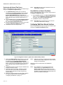
1
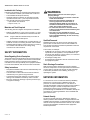
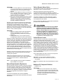
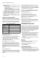
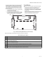
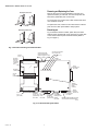
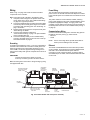
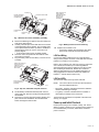
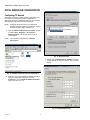
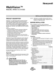
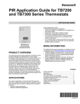
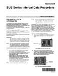
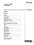
WebVision™
MODEL WWS-VL1A1000
INSTALLATION INSTRUCTIONS
PRODUCT DESCRIPTION
WebVision™ is a web-based building manager that allows
contractors and facility managers to view and command
HVAC controllers installed in their sites. It communicates over
the LonWorks® network to perform building management
control of various devices and controllers through a web
browser. The WebVision Bundle (WWS-VL1A1000) includes
the WebVision controller, a pre-installed LON card, and power
supply.
WebVision is capable of:
• Discovering unitary controllers connected to WebVision
• Configuring controllers using configuration wizards
• Monitoring and raising alarms on controller points
• Configuring and collecting trends on points
• Driving scheduled occupancy states
• Managing energy through Demand Limit Control (DLC)
• Providing single point of entry into the system to perform all
the above mentioned tasks.
WebVision acts as an offline configuration tool that helps the
contractor to configure site project that consists of multiple
unitary controllers. The contractor can commission all the
controllers by connecting through a LAN, WAN, or Dial-up.
WebVision also acts like a network time master to synchronize
time and date in devices connected to it with its own time and
date or with the Internet time servers. Its Device Discovery
feature enables you to discover online devices. You can
manage users and control their access to different resources
in the system. The System Administrator can configure
network settings, site information settings, system and control,
network data and time settings, and new module installation.
For more information about WebVision, refer to “About
WebVision” on page 15.
Approvals
UL 916, C-UL listed to Canadian Standards Association (CSA)
C22.2 No. 205-M1983 “Signal Equipment”, CE, FCC part 15
Class A, C-tick (Australia)
CAUTION
Make sure that there is not more than one
WebVision accessing the same Lon® network
simultaneously. If more than one WebVision
accesses the same Lon network simultaneously,
there may be problems in downloading and
uploading parameters.
NOTE: WebVision is compatible with Microsoft® Internet
Explorer® (IE) 6.0 SP2 or higher. Suggested screen
resolution is 1280x1024 pixels.
BEFORE INSTALLATION
Prior to installation, ensure you have the following:
• WebVision Installation Instructions (this document)
• WebVision Controller
• Power Adapter
• LON Connector pin
• Ethernet CAT 5 cable with RJ-45 connectors
• Laptop/PC to perform the initial configuration
• Cable for grounding
• Determined the installation network and Internet
requirements
Unpacking
1.
2.
3.
4.
Unpack the controller.
Inspect contents of the package for damaged or missing
components.
Check the equipment and report any damage to a Honeywell representative at once and return any damaged
components for immediate repair or replacement. For
product warranty and returns, please refer to the WebVision User Guide (form 95-7759)
Read all of these instructions and ensure they are
understood.
Contents
Product Description ........................................................
Approvals ...................................................................
Before Installation ...........................................................
Safety Information .....................................................
Network Information ..................................................
Hardware Installation ......................................................
Mounting ....................................................................
Wiring ........................................................................
LON Card ..................................................................
Power-up and Initial Checkout ...................................
Initial WebVision Configuration .......................................
About WebVision ............................................................
Appendix ........................................................................
Network Setup Worksheet .........................................
Maintenance ..............................................................
Replacement Parts ....................................................
Technical Support, Warranty, and Returns ................
Certifications ..............................................................
1
1
1
2
2
4
4
7
8
9
12
15
17
17
18
18
19
19
62-0319-03
WEBVISION™ MODEL WWS-VL1A1000
Included in this Package
WARNING
Included in this package you should find the following items:
• One WebVision controller, pre-installed with a LON card
• This Installation Guide (form 62-0319).
• Hardware package containing one grounding wire with
quick-disconnect 0.187 in. (4.75 mm) female connector.
• One external wall-mount power adaptor:
• Input: 90-254 Vac, 50-60 Hz
• Output: 15 Vdc, 1 A
Materials and Tools Required
The following tools and supplies are required for installation:
• DIN rail, type NS35/7.5 (1.4 IN. X 0.3 in. [35 mm x 7.5 mm])
recommended for any installation that includes a DIN rail.
NOTE: Length of DIN rail is determined by the number of
optional DIN-mounted options.
• Suitable screws and screwdriver for mounting DIN rail, or if
a DIN rail not used, for mounting the base of the controller.
• Small flat-blade screwdriver used for mounting or removing
the controller from DIN rail and for making wiring
connections to LON connectors.
SAFETY INFORMATION
Notes Regarding Device Description
These instructions include indications for use and mounting of
the device. In case of questions that cannot be answered with
these instructions, please consult the product supplier or
manufacturer. It is the responsibility of the equipment installer
to ensure that all federal, state and local codes are followed.
Safety Instructions
• Keep these Installation Instructions for industrial safety and
the prevention of accidents.
• The information in these instructions must be read and
understood by every person using this device.
• The following items share warnings of a general nature
relating to the installation and start-up of the controller.
• Be sure to heed these warnings to prevent personal injury
or equipment damage.
Risk of electrical shock. Can cause injury or
property damage.
• The circuit powering the controller is from 100
to 240 Vac at 50/60 Hz.
• Disconnect power before installation or
servicing to prevent electrical shock or
equipment damage. Make all connections in
accordance with national and local electrical
codes. Use copper conductors only.
• To reduce the risk of fire or electrical shock,
install in a controlled environment relatively free
of contaminants.
• This device is only intended for use as a
monitoring and control device. To prevent data
loss or equipment damage, do not use for any
other purpose.
Qualified Personnel
Qualified personnel in the sense of these instructions are
persons who are well versed in the use and installation of
such devices and whose professional qualification meets the
requirements of their work.
This includes, for example:
• Qualification to connect the device according to applicable
specifications and regulations, and a qualification to put
this device into operation, to power it down, or to activate it
by respecting the internal directions.
• Knowledge of safety rules.
• Knowledge about application and use of the device within
the equipment system.
Static Discharge Precautions
Static charges produce voltages high enough to damage
electronic components. The microprocessors and associated
circuitry within a controller are sensitive to static discharge.
Follow these precautions when installing, servicing or
operating the system:
NETWORK INFORMATION
For access from a local or wide area network (LAN/WAN),
WebVision is connected to the LAN/WAN. Ensure the
presence of a network administrator. In case there is no
network administrator, it might be necessary for the installer or
the facility manager to consult an independent network
professional. Internet access to WebVision is frequently
provided through a LAN/WAN. Prior to installation, identify the
procedures for connecting WebVision to the LAN/WAN and
gain Internet access.
Network Security
As with any Internet web server, WebVision is subject to
attack by hackers. While WebVision is supplied with the best
available internal protection, a network firewall must be used if
Internet access is provided. Review the Internet, LAN, or WAN
provisions for installation and determine the appropriate
firewall requirements.
62-0319—03
2
WEBVISION™ MODEL WWS-VL1A1000
IMPORTANT
1. When connecting WebVision to the Internet directly,
or through a LAN or WAN, use of additional external
security measures such as a firewall is strongly
advised.
2. When connecting WebVision directly to the Internet
from a cable/DSL modem with no network, a firewall
must be established by adding a router. (Simple
switches and hubs are insufficient.)
3. Most routers used with cable/DSL modems provide a
significant level of hardware protection and network
address translation (NAT), and have the ability to
implement a software firewall as well. Such routers
are widely available at nominal cost.
Generally, local and wide area networks have sophisticated
firewall protection and it is necessary to work with a network
administrator to install WebVision properly. Network
reconfiguration might be needed to support WebVision. If the
installer or end user does not have the expertise required to
determine the network capabilities or to set up an appropriate
firewall, consult a network specialist.
IMPORTANT
1. Networks configured with the Microsoft Windows®
Network Setup Wizard as a proxy server (the
recommended wizard procedure) may not support
WebVision.
2. Installing WebVision in such a network requires
reconfiguring the network for peer-to peer operation.
WebVision has been designed with many features to promote
Internet security. The most basic is the user ID and password
access to the system. WebVision has a default user ID and
password for initial installation. After installation, each
individual user is provided with a unique ID and password.
Internet best practices recommend IDs and passwords that
are eight characters or more in length with a mix of alpha and
numeric characters. Best practices also require individual
users to change passwords periodically. As with any system,
when personnel changes occur, old IDs and passwords must
be deleted and new ones assigned.
WebVision closes all unused internal software access ports. It
is designed to allow access through HTTP port 80 during
normal system operation.
Initial setup of WebVision requires a PC to be physically
connected to WebVision’s Ethernet port. When configuration
is completed, remove the PC – WebVision Ethernet
connection.
NOTE: Future upgrades and service packs for WebVision
will be available on the Internet.
Static or Dynamic Address Option
It is necessary to provide an IP (Internet Protocol) address for
WebVision in order to communicate with it.
WebVision supports both static and Dynamic Host
Configuration Protocol (DHCP) IP addressing. A static IP
address is one that is permanently assigned to WebVision and
is provided by the ISP or LAN/WAN network administrator.
A dynamic IP address is one that is assigned by another
network device (DHCP Server) and can change based on
rules established for the network.
DHCP is supported in WebVision, though static IP addresses
provide the most reliable connectivity.
CAUTION
Honeywell does not recommend using the DHCP
addressing mechanism, where the IP address is
dynamically assigned to WebVision. Unless the IP
address is known, WebVision cannot be accessed.
To reliably use DHCP, we recommend that you
reserve an IP address in the DHCP server for the
MAC address of WebVision. This ensures that the
controller receives the same IP address whenever
it requests one from the DHCP server.
Uniform Resource Locator
A Uniform Resource Locator (URL) is required to address
WebVision with Microstate Internet Explorer. In many
installations, the URL will be routed through a Dynamic Name
Service (DNS) to address WebVision. However, DNS is not
required for installations using an Ethernet DHCP address. If
DNS is used, the information for WebVision setup data must
be obtained prior to setup. This can require obtaining a
registered domain name from a Domain Name registration
service. The information should be available from the facility’s
network administrator and/or ISP. The processes for setting
up DNS service vary depending on the ISP, DNS service, and
the user’s LAN/WAN operating policies and are beyond the
scope of this document.
Using a DNS address, the URL is in the form of the protocol:
//FullyQualifiedDomainName/resource.
Alternatively, you can use the IP Address to access
WebVision. The URL will be in the form of the protocol:
//IP_Address
Refer to the “WebVision URL Component Definitions” section
below.
Network Setup Information Requirements
Specific information about the network is required to configure
the network interface of WebVision. “Setup Data Description”
on page 4 identifies the data required for each configuration
option. This information should be gathered prior to setting up
WebVision. The “Appendix” on page 17 is provided to record
and collect all applicable data required to configure
WebVision.
In local area network/wide area network (LAN/WAN)
applications, the data required will be provided by the network
administrator.
3
WebVision URL Component Definitions
• protocol = http
IMPORTANT
The protocol must be entered as ‘http’. Entering
incorrect protocol results in an error message, “The
page cannot be displayed”. Internet Explorer defaults
to the http protocol which results in the error
message, “FullyQualifiedDomainName (FQDN) =
hostname.domainname”.
62-0319—03
WEBVISION™ MODEL WWS-VL1A1000
• domain.name = the domain name assigned by the ISP or
network administrator.
— The domain name must be registered if it is to be used
through the Internet.
— WebVision installed in a LAN/WAN must be provided
by the network administrator.
— WebVision installed in a small network using a Cable/
DSL router can require configuring the router DMZ or
port redirection to provide access.
• hostname = the host name for WebVision (host) assigned
by the installer during configuration. Refer to “Setup Data
for Configuration Options” on page 4.
• IP address = the static IP address assigned by the ISP,
network administrator, or the dynamic IP address assigned
by the DHCP host.
Setup Data for Configuration Options
Table 1 captures the data required for a Static IP address
configuration. This section describes each configuration data
prompt with an indication of where the data can be obtained.
If the installer is not familiar with the processes required to
configure network devices, consult a networking specialist.
Table 1. IP Address Options.
IP Address Options
[DNS 1 Domain Name Server] WAN (cable/DSL modem)
This is the DNS address (first in the list). This is necessary for
e-mail alarm notification. You can access it from the router or
the ipconfig /all command. In router setup, look for DNS and
use the first address in the list (primary).
To access from a PC, click Start > Run and type cmd. Type
ipconfig/all and look for DNS Servers and use the first
address in the list (primary).
[Local Host Name] WebVision name
This is assigned by the user. Type any unique name;
WebVision is recommended. Names can be in only
alphanumeric characters. Only two special characters are
allowed, the dash “-” and the underscore “_”.
[Domain Name] ISP domain name:
This is not a user’s domain name. It is necessary for alarm
and e-mails to be sent correctly. To access from a PC, click
Start > Run and type cmd. Type ipconfig/all and look for
Connection specific DNS Suffix.
HARDWARE INSTALLATION
Static
This section covers the mounting and wiring of the Honeywell
WebVision Controller, the LON card mounting and wiring, and
initial power-up,. It is assumed that the installer is a trained
engineer, technician, or service person, and is fully qualified to
install control systems. Instructions in this document apply to
the following products. Please read this entire document
before beginning the installation procedures.
IP Address
Network Mask
Gateway IP Address
DNS 1 Server
DNS 2 Server
Setup Data Description
[IP Address] WebVision IP address - user assigned
This is the LAN/WAN IP address which applies to WebVision
in static IP configurations. It is not applicable in DHCP
configurations. The IP address consists of four sets of
numbers separated by a decimal point. The valid values for
each number range from 0 to 255.
When installing this product:
• Read the instructions carefully. Failure to follow them could
damage the product or cause a hazardous condition.
• Check ratings given in instructions and on the product to
ensure the product is suitable for your application.
• Installer must be a trained and an experienced service
technician.
• After installation is complete, check out product operation
as provided in the instructions.
Mounting
[Network Mask] LAN Subnet Mask address
Mount the controller in a location that allows clearance for
wiring, servicing and module removal.
This is applicable only to Ethernet Static IP configurations.
You can configure the Network Mask from the router or use
the command, ipconfig /all, executed on the command line on
a PC that is on the same network. To access from a PC, click
Start > Run and type cmd. Type ipconfig/all and look for
Subnet Mask. To configure from a router, refer to the Router
Manual.
Additional mounting information applies as follows:
• Environmental Requirements
• Physical Mounting
[Gateway IP Address] LAN
This is applicable only to Ethernet Static IP configurations. It is
the default Gateway address. To access from a PC, click Start
> Run and type cmd. Type ipconfig/all and look for Default
Gateway.
62-0319—03
4
Environmental Requirements
The following are the environmental requirements for the
mounting locations of the controller.
• This product is intended for indoor use only. Do not expose
the unit to ambient conditions outside of the range of 32° to
122° F (0° to 50° C) and relative humidity outside the range
of 5% to 95% non-condensing (pollution degree 1).
WEBVISION™ MODEL WWS-VL1A1000
• If mounting inside an enclosure, that enclosure should be
designed to keep the unit within its required operating
range considering a 20-watt dissipation by the controller.
This is especially important if the controller is mounted
inside an enclosure with other heat producing equipment.
• Do not mount the unit:
— in an area where excessive moisture, corrosive fumes,
or explosive vapors are present.
— where vibration or shock is likely to occur.
— in a location subject to electrical noise. This includes
the proximity of large electrical contractors, electrical
machinery, welding equipment, and spark igniters.
1/64
(4 MM)
Physical Mounting
The following information applies to physically mounting the
unit:
• The unit may be mounted in any orientation. It is not
necessary to remove the cover before mounting.
• The unit may be mounted on a 1.4 in. (35 mm) wide DIN
rail if available. The unit base has a molded DIN rail slot
and locking clip.
• If DIN rail mounting is impractical, use screws in mounting
tabs on the controller, then in any end-connected
accessory. Tab dimensions are shown in Fig. 1.
6-23/32 (171 MM)
CONTROLLER
3-3/4 (95 MM)
4
(102 MM)
2-1/2
(64 MM)
M28768
Fig. 1. Controller mounting tab dimensions in inches and (mm).
Table 2 provides step by step instructions to mount the controller onto a DIN rail.
Table 2. Mounting onto a DIN rail.
Step
1
Action
Securely install the DIN rail using at least two screws, near both ends of the rail.
2
Position the controller in the rail, tilting to hook DIN rail tabs over one edge of the DIN rail (see Fig. 2 on page 6).
3
Use a screwdriver to pry down the plastic locking clip, and push down and in on the controller, to force the locking clip to
snap over the edge of the DIN rail.
4
To prevent the controller from sliding on the DIN rail, secure with clips provided by the DIN rail vendor, or place a screw in
one of the 4 mounting tabs in the base.
5
Mount any accessory item onto the DIN rail in the same manner.
6
Slide the accessory along the DIN rail to connect its 20-position plug into the controller.
7
Repeat this for all accessories, until all are mounted on the DIN rail and firmly connected to each other.
8
To keep this assembly from sliding on the DIN rail, secure the last accessory with clips provided by the DIN rail vendor, or
place a screw in one of the mounting tabs in the base of the last accessory.
5
62-0319—03
WEBVISION™ MODEL WWS-VL1A1000
Removing and Replacing the Cover
MOUNTING ON DIN RAIL
Remove the cover to connect the battery (new unit) or to
replace the battery or LON card. The cover snaps onto the
base with 4 plastic tabs (two on each end).
To remove the cover, press in the 4 tabs on both ends of the
unit, and lift the cover off.
To replace the cover, orient it so the cutout area for common
ports is correct, then push inward to snap in place.
M23265
Board Layout
REMOVING FROM DIN RAIL
Fig. 3 shows the location of LEDs, option slots, and other
features of the controller with cover removed. For a side view
of the communications ports and other features (Refer to
Fig. 4 on page 7).
M23266
Fig. 2. Controller mounting and removal details.
OPTION
SLOT 2
BATTERY
BRACKET
(ON TOP
OF OPTION
CARDS, IF
ANY)
SERIAL PORT LEDS
ON BOTTOM BOARD,
REMOVE COVER TO SEE:
COM1
STATUS LEDS (VISIBLE
WITH COVER ON):
COM2
LAN2
LAN1
BEAT
STATUS
20 PIN
CONNECTOR
NOT USED
BATTERY
CONNECTOR
OPTION
SLOT
CONNECTORS
MODE
JUMPER
(FOR SERIAL
SHELL
ACCESS)
OPTION
SLOT 1
(LON CARD)
SECONDARY
ETHERNET
(RJ-45) LAN2 RS-232 (DB-9)
(TOP BOARD) COM1
NOT USED
NOT USED
PRIMARY
ETHERNET
(RJ-45) LAN1
(TOP BOARD)
EARTH
GROUND
USB PORT
SPADE LUG
(TOP BOARD)
NOT USED
RS-485
(3-POSITION)
COM2 (BOTTOM
BOARD)
BARREL POWER CONNECTOR FOR
NOT USED
WALL MOUNTED POWER MODULE
M28769
Fig. 3. Controller board layout details.
62-0319—03
6
WEBVISION™ MODEL WWS-VL1A1000
Wiring
Power Wiring
Refer to Fig. 3 on page 6 to locate connectors and other
components on the controller.
Make connections to the controller in the following order.
1. If required, make changes to the position of the LON
card in option slots 1 and 2. See “LON Card Mounting”
on page 8 for a general procedure.
2. Connect the supplied earth grounding wires (with spade
connectors) from the earth ground lug on the controller
to a nearby earth grounding point. See “Grounding” on
page 7 for details.
3. Prepare power wiring (leave the unit powered off). See
“Power Wiring” for details.
4. Connect communications cables. See
“Communications Wiring” on page 7 for ports available
on the controller base unit.
5. Connect the backup battery to the controller battery
connector, and apply power to the unit. See “Power-up
and Initial Checkout” on page 9.
Grounding
An earth ground spade lug 0.187 in. (4.75 mm) is provided on
the base of the controller for connection to earth ground. For
maximum protection from electrostatic discharge or other
forms of EMI, connect the supplied earth grounding wire to
this lug and a nearby earth ground. Keep this wire as short as
possible.
IMPORTANT
Connect the earth ground spade lug of each
accessory module to ground in the same manner.
The controller must be powered by an approved 15 Vdc
power source. An external wall mount AC adapter is included
in the controller pack. The controller does not include an on/off
switch.
The power module is a self-contained, isolated, switching
power supply designed to plug into a standard building power
receptacle of appropriate voltage. To supply power to the
controller, plug the barrel connector plug from the module into
the barrel power connector on the controller board (see Fig. 3
on page 6).
Communications Wiring
Connect communication wiring to the controller using ports on
the bottom of the unit (see Fig. 4), which include:
• Ethernet
• Serial
NOTE: Prior to connecting cables, provide strain relief for
them to prevent damage to the controller.
Ethernet
Two female 10/100-Mbit Ethernet connections are provided
on the controller. These are RJ-45 connectors labeled LAN2
and LAN1. Use a standard Ethernet patch cable for
connecting to a hub or Ethernet switch. An activity LED for
each Ethernet port is visible, and are labeled LAN2 and LAN1
on the cover.
Make the earth ground connection to the grounding lug using
the supplied earth wire.
SECONDARY
ETHERNET
(RJ-45) LAN 2
NOT USED
BATTERY IN BRACKET
(ON TOP OF OPTION
CARDS, IF ANY)
PRIMARY
ETHERNET
(RJ-45) LAN 1
USB PORT
NOT USED
20 PIN
CONNECTOR
NOT USED
BATTERY
CONNECTOR
EARTH
GROUND
SPADE LUG
OPTION SLOT AREA
(SLOT #1 THIS SIDE)
LON CARD
RS-232
(DB-9)
COM1
NOT USED
RS-485
(3-POS.)
COM2
NOT USED
BARREL CONNECTOR
FOR WALL MOUNTED
POWER MODULE
M28770
Fig. 4. Controller bottom side view (cover removed).
7
62-0319—03
WEBVISION™ MODEL WWS-VL1A1000
Connecting to LAN/WAN
Fig. 5 depicts the wiring needed to connect WebVision to
LAN/WAN. It also shows the PC/Laptop that will be used for
initial configuration.
The second distribution file can be used to re-enable LAN2
port to default factory settings 192.168.1.120. After this, the
LAN2 port will be available again as another gateway into the
system, especially useful for on-site maintenance.
.
LON Card
LAN HUB/SWITCH
This section covers the mounting and wiring of the LON card
in a Honeywell WebVision Controller. For related Controller
installation details, See “Hardware Installation” on page 4.
The LON card uses an FTTP-10A LON (LONWORKS) adapter
with a 2-position removable screw-terminal connector plug.
NOTE: The LON card may be installed on the other side
(empty slot). See Fig. 7 for location of option slots.
ETHERNET CABLE
WEB VISION
PRIMARY LAN 1 PORT
LON Card Mounting
PC
WARNING
M28771
Fig. 5. WebVision Network Connection Diagram.
Power to the Controller must be OFF when
removing option cards, or damage will occur!
Also, be very careful to plug any option card into
its connector properly (pins aligned).
LAN Hub/Switch can be as simple as a HUB all the way to a
Switch with Router features.
Primary and Secondary interface varies from network to
network. WebVision comes with the following default network
configuration
Mount the LON card in either of the option card slots of the
Controller, as available.
.
PRIMARY LAN 1 INTERFACE
• Enabled: true
• Host Name: WebVision
• Domain Name: WebVision
• DHCP Enabled: false
• IP Address: 10.0.0.1
• Subnet Mask: 255.0.0.0
• Default Gateway: 10.255.255.254
• DNS Server: 10.0.0.3
RX TX
LON
SECONDARY LAN 2 INTERFACE
• Enabled: true
• IP Address: 192.168.1.120
• Subnet Mask: 255.255.255.0
Due to hardware and firmware restrictions, the two LAN ports
cannot be assigned IP addresses on the same subnet. For
example, if the user tries to change the primary IP address
from 10.0.0.1 to 192.168.X.X, the operation may not be
completed as it then conflicts with LAN2 port settings.
To address this need, two software distribution files are
provided on the buildings forum (http://
buildingsforum.honeywell.com). One can be used to disable
LAN2 port entirely so that any IP settings can be used on
LAN1 port. This may also be required for security reasons on
certain sites. The drawback is that if the primary IP settings
are lost or corrupt, there is no way to recover the controller.
62-0319—03
8
M23324
Fig. 6. LON Card.
1.
2.
Power down the Controller (see WARNING above).
Remove the Controller cover.
• Press in the four tabs on both ends of the unit, and lift
the cover off.
NOTE: If accessory modules are plugged into the
Controller, slide them away from the unit to get
to the cover tabs.
3.
Remove the battery and bracket assembly by taking out
the four screws holding it in place, setting the screws
aside for later.
• Unplug the battery from the connector on the
Controller.
WEBVISION™ MODEL WWS-VL1A1000
HAND TIGHTEN THE
FOUR SCREWS
THROUGH BATTERY
BRACKET, END
PLATES, INTO
STANDOFFS
SCREWS (4)
BATTERY ASSEMBLY
(INCLUDES CABLE
AND BRACKET)
UNPLUG BATTERY HERE
OPTION SLOT
2 AREA
BLANKING END
PLATE
OPTION SLOT
1 AREA
M23694
Fig. 7. Removal of screws and battery assembly.
4.
5.
6.
7.
Remove the blanking end plate for the slot in which the
LON card is being placed.
Carefully insert the pins of the LON card into the socket
of the appropriate option card slot. The mounting holes
on the option board should line up with the standoffs on
the base board. If they do not, the connector is not
properly aligned.
• Press until the LON card is completely seated.
Place the custom end plate that came with the LON
card over its connector.
Plug the battery cable into the battery connector on the
Controller.
INSERT LON CARD INTO
OPTION CARD SLOT
CAREFULLY, WITH
PINS ALIGNED. FULLY
SEAT CARD.
M23327
Fig. 9. Battery bracket screw re-fastening.
10.
Replace the Controller cover.
• If accessory modules were unplugged, plug them
back into the Controller as before and secure.
LON Card Wiring
Connect the LON (LONWORKS FTT-10) communications
wiring to the 2-position connector of the LON card. Note that
polarity is not a factor in FTT-10 wiring.
Refer to the LONWORKS FTT-10A Free Topology Transceiver
User’s Guide (078-0156-01F) for technical guidelines
associated with free topology restrictions, and the Junction
Box and Wiring Guidelines for Twisted Pair LONWORKS
Networks (005-0023-01) for more detailed information on
wiring specifications. These documents are available on
Echelon’s® web site (www.echelon.com).
BATTERY
CONNECTOR
LON Card LEDs
Two LEDs are visible on the top of the LON card.
PLACE LON CARD
CUSTOM END PLATE
OVER END
NOTE: The cover must be removed from the Controller to
view the installed LON card.
M28772
Fig. 8. Top view, LON Card end plate insertion.
8.
9.
Set the battery and bracket assembly back over the
option card slots, with the mounting holes aligned with
the standoffs.
Place the four screws through the battery bracket, end
plate, and into the standoffs on the Controller base
board. Hand tighten these screws.
• RX (green) - Receive, indicates that another LONWORKS
device is transmitting a message.
• TX (yellow) - Transmit, indicates that the Controller is
transmitting a message on the LON trunk.
These LEDs are included on the top label of the LON card,
See Fig. 6 on page 8.
Power-up and Initial Checkout
Ensure power wiring to the controller is ready; see “Power
Wiring” on page 7. Refer to Fig. 3 on page 6 for the location of
the controller battery connector, status LEDs, and barrel
power connector.
9
62-0319—03
WEBVISION™ MODEL WWS-VL1A1000
charged again as necessary. The power and battery circuitry
is monitored by a station running on the controller (via the
Power Monitor Service). Station alarms are generated
whenever primary power is lost or if the battery is uncharged
or unable to hold sufficient charge.
After all mounting and wiring procedures are completed,
perform the following procedure:
Initial Power and Checkout
1.
2.
3.
“Connect the Backup Battery” (this page).
“Apply Power” on page 10.
“Check the Status LEDs” on page 10.
The battery should be replaced approximately every three
years or more often if the unit is in a high temperature
environment.
Connect the Backup Battery
With the cover removed from the controller, (See “Removing
and Replacing the Cover” on page 6), locate the red and black
wires coming from the backup battery with the 2-position
connector plug. Insert the plug into the battery connector on
the bottom board (below the option slot 2 area), as shown in
Fig. 10.
NOTE: A NiMH battery characteristic is to lose charge if not
left in charge mode (trickle charge). Leaving the
battery unconnected, or the unit powered off will
cause the battery to fully discharge in a matter of
weeks. In the case of a new controller the battery is
shipped completely discharged. Therefore, allow at
least 18 hours for the battery to charge if it has not
been in a powered unit.
For more information on the use and replacement of the
battery, refer to “Required Battery Maintenance” on page 18.
BATTERY
ASSEMBLY
Apply Power
Apply power to the controller by plugging in the power plug
into the controller.
Check the Status LEDs
When power is applied, the green LED labeled STATUS will
light. This indicates that the system is OK and that power is
applied. Once the controller boots, the yellow BEAT
(heartbeat) LED begins blinking with a typical rate of
approximately 1 Hz. Blinking should begin within 30 seconds
after power is applied.
BATTERY
CONNECTOR
M29292
If after applying power, the STATUS LED goes out, or if the
BEAT LED comes on (steady) and stays lit longer than two
minutes, refer to “Using Status LEDs” below.
Fig. 10. Backup battery connector on bottom board.
The connector is keyed. It cannot be inserted incorrectly. The
red (positive) connections should be the furthest from the two
30-pin option board connectors.
BATTERY
The controller is provided with a custom 10-cell NiMH battery
pack mounted to the unit (under the cover). This battery
allows the controller to continue operation through very short
power bumps (a few seconds in duration). If a longer power
outage occurs, the battery provides enough run time to
backup data and then shutdown. Typically, this is one minute.
Shutdown occurs automatically after data is backed up to onboard flash memory.
The controller charges the battery during normal operation
until fully charged. Typically, the charge operation completes
within 18 hours. Following a power outage, the battery is
62-0319—03
10
Using Status LEDs
The controller includes several LEDs (see Table 3) that can
help determine the status of the unit. They are located in two
places: the top of the controller (visible through the cover),
and on the bottom board (visible only with cover removed).
From left-to-right, these LEDs include:
• Ethernet Ports
• Heartbeat
• Status
• Serial Ports
Refer to Fig. 3 on page 6 for the exact locations of status
LEDs on the controller.
WEBVISION™ MODEL WWS-VL1A1000
Table 3. LED Status and Activity.
Controllers
Color of LED
LED Off
LED On
LED Blinking
Location
LED’s Activity
Ethernet Port
(Primary)
Green
No Ethernet link Ethernet link is
is established
present, but no
activity on LAN
Ethernet link is
present with
data activity on
LAN
Top cover
Shows the
status of the
Ethernet link
Ethernet Port
(Secondary)
Green
No Ethernet link Ethernet link is
is established
present, but no
activity on LAN
Ethernet link is
present with
data activity on
LAN
Top cover
Shows the
status of the
Ethernet link
Heartbeat
Yellow
N/A
N/A
Blinks once per Right of the
second
Ethernet status
LEDs
Indicates normal
operation
Status
Green
Error condition
Whenever the
WebVision is
powered
N/A
Provides a CPU
machine status
check
11
Right of the
heartbeat
(“BEAT”) LED
62-0319—03
WEBVISION™ MODEL WWS-VL1A1000
INITIAL WEBVISION CONFIGURATION
Configuring PC Network
WebVision comes with a default network configuration. The
PC/Laptop that will be used for initial configuration of
WebVision should be configured so that it can communicate
with WebVision using Microsoft Internet Explorer.
NOTE: PC/Laptop should be running one of Microsoft
Windows operating systems. It should have Internet
Explorer 6.0 SP2 or higher installed on it.
1.
Open the Network and Dial-up Connections window.
(Location: Start > Programs > Accessories >
Communications). The window shown in Fig. 11
should appear.
NOTE: The equivalent in Windows XP is Network
Connections.
Fig. 12. Properties Page.
3.
Double click “Internet Protocol (TCP/IP) to open the
TCP/IP Settings. A popup as shown in Fig. 13 should
appear.
Fig. 11. Network and Dial-up Connections Window.
2.
Right click on the appropriate LAN adapter that will be
used for configuring the WebVision and click
Properties to open the Network Adapter Properties
popup as shown in Fig. 12.
Fig. 13. TCP/IP Settings Page.
62-0319—03
12
WEBVISION™ MODEL WWS-VL1A1000
IMPORTANT
Before making any changes here, note the values in
each field, as this information is needed to restore
the network configuration back to original.
As illustrated in Fig. 13 on page 12, provide the following
information in the respective fields:
• Click the button for – Use the following IP Address
• IP Address: 10.0.0.2
• Subnet Mask: 255.0.0.0
• Default Gateway: 10.0.0.254
• DNS1 Server: 10.0.0.3
• DNS2 Server: 10.0.0.4
4.
5.
Click OK on both the pop-ups. Restart the PC/Laptop if
required.
Open the command prompt on the PC/Laptop:
a. Click Start > Programs > Accessories >
Command Prompt or
Click Start > Run and type cmd
b. Ping WebVision by executing the following
command to check if the communication has been
established: C:\> ping 10.0.0.1
NOTE: If the ping fails, recheck your network configurations
and network connections. If the problem still persists,
contact the network administrator for assistance.
Initial WebVision Login
To log on to WebVision from the PC/Laptop:
1. Open Internet Explorer on the PC/Laptop.
2. In the address bar, type http://10.0.0.1 and press the
Enter key. The browser should open the WebVision
login page as shown in Fig. 14.
Fig. 14. WebVision Login Screen.
3.
4.
Provide User ID and Password as SysAdmin and
!Sys!Admin correspondingly to login.
Click the System tab. The System Configuration page
displays as shown in Fig. 15.
Fig. 15. Configuration window - System Tab - General sub-tab.
Adjusting WebVision System Clock
1.
Refer to “Initial WebVision Login” for steps to login and get to
the System Configuration page.
2.
13
From the System tab and General sub-tab, in the Time
and Date Settings section, select the appropriate
TimeZone and click Save.
If the Time Zone is changed, WebVision will prompt you
to reboot WebVision. Click Yes to proceed. It will take
about 5 minutes for WebVision to boot. After 5 minutes,
re-login following the steps given in “Initial WebVision
Login”.
62-0319—03
WEBVISION™ MODEL WWS-VL1A1000
Synchronize with Internet Time Source
Refer to “Initial WebVision Login” on page 13 for steps to login
and get to the System Configuration page.
1.
2.
3.
4.
In the Network Setup sub-tab, fill in the network
information. The required information can be obtained
from the Network Setup Worksheet (reference the
Network Setup Worksheet in the “Appendix” on
page 17) that you have completed using the instructions
in the “Network Setup Information Requirements” on
page 3.
On the General sub-tab in the Time and Date Settings
section, check the Use Internet Time Server check
box. This enables the Sync Now button.
Select the appropriate Internet Time server from the list
provided in Time Server Address combo box.
Click Save to save the changes made.
NOTE: Sync Now will fail to work if WebVision is set to an
initial default IP address.
Setup WebVision as Network Time Master
Refer to “Initial WebVision Login” for steps to login and get to
the System Configuration page.
1.
2.
On the General sub-tab in the Time and Date Settings
section, check the WebVision is Network Time Server
check box. This enables the Sync Now button.
Click Save to save the changes made.
NOTE: Sync Now will do nothing if there are no devices
connected to WebVision to manage.
Configuring WebVision Network Interface
Refer to “Initial WebVision Login” on page 13 for steps to login
and get to the System Configuration page.
Fig. 16. Configuration window - System Tab - Network Setup sub-tab.
1.
2.
3.
4.
Click on the Network Setup sub-tab (see Fig. 16), enter
the network information. The required information can
be obtained from the Network Setup Worksheet
(reference Network Setup Worksheet in “Appendix” on
page 17) that you have completed using the instructions
in the “Network Setup Information Requirements” on
page 3.
Click Save to save the network changes. WebVision will
prompt to reboot the system.
Click Yes to reboot the system. WebVision will take
about 5 minutes to reboot. Wait for 5 minutes and
access it again. WebVision will start using the new
network settings.
Restore the network settings of the PC/Laptop. Refer to
the original settings that have been suggested in
“Configuring PC Network” on page 12.
62-0319—03
14
NOTE: WebVision cannot be accessed from the PC/Laptop
that was used for initial configuration until its network
settings are restored back.
WebVision can be accessed from the LAN/WAN as
configured.
NOTE: Now, WebVision can synchronize its time with
Internet Servers. The Sync Now button in the
System > General tab can be used to force time
synchronization. Synchronization will succeed only if
the DNS is configured properly and the Internet Time
Server is accessible to WebVision.
WEBVISION™ MODEL WWS-VL1A1000
ABOUT WEBVISION
Information for Network Administrators
The following information may be required by the network
administrator and/or ISP prior to installation of WebVision.
Copy this section, “Information for Network Administrators”,
and give it to the network administrator or ISP contact.
Ports Used
WebVision web access requires the following network port to
be open for Internet access:
• Port 80 – HTTP Connection to WebVision from Internet
NOTE: Network proxy servers can interfere with network
access to WebVision. To minimize the interference,
the proxy server may need re-configuration.
DNS and WINS Support
WebVision supports and uses DNS for sending alarm
information through Electronic Mail. If WebVision is configured
to use a static IP address, it would be convenient to register
WebVision’s host name and IP address in a DNS server so
that WebVision can be accessed using a Fully Qualified
Domain Name instead of an IP address.
WebVision does not support WINS name resolution.
WebVision:
• Support up to 120 XL10s, XL15Cs, VFDs, and 3rd Party
LON devices
• Perform Auto Discovery and Wizard based
configuration of controllers
• Support Default Alarms on each device
• Support Default Trends on each device
• Support default device graphic for each device
• Configure a maximum of 30 users and define their roles in
accessing and configuring devices and WebVision
• Configure a maximum of 50 schedules
• Configure and schedule device occupancy states
• Assign up to 120 devices per schedule
• Configure a maximum of 100 trends
• Store up to 1,000 samples per trend
• Configure up to 100 user defined alarms
• Store and view up to 5,000 alarm records
• E-mail alarm messages can be sent to a maximum of
50 e-mail addresses
• Configure up to 50 loads for Demand Limit Control
• Configure default and up to 50 user-defined graphics with
support to command-able points
Connection Protocol and IP Address
WebVision is built on Niagara-AX™ technology and extends
the capabilities of WebStat™.
WebVision supports Ethernet protocol and either Static or
DHCP IP addressing.
Graphics
Identify the IP addressing type as static or DHCP:
• For static addressing, provide the static IP address.
• For DHCP, the DHCP server assigns the IP address.
A graphic is a pictorial illustration of building's layout coupled
with the placement of various devices within a building. With
the help of a graphic you can view the various devices
installed in your building.
Uniform Resource Locator (URL)
WebVision URL is structured as scheme://domainname,
where:
• Scheme = http
• Domainname = IP address or Fully Qualified Domain
Name (FQDN)
NOTE: Fully Qualified Domain Name (FQDN) is assigned by
the network administrator or ISP.
Electronic Mail Options
WebVision can be configured to send e-mail to an SMTP
e-mail server within the LAN/WAN to which it is connected. If a
LAN/WAN SMTP server is to be used, the SMTP server name
is required. This may be necessary if the local network
requires an e-mail to be delivered only through a network
e-mail server. Consult the site IT System Administrator for the
correct settings.
Upgrades and Service Packs
Future upgrades and service packs for WebVision will be
made available by download from the Internet. Specific
instructions for downloading and installing upgrades and
service packs will be communicated as part of the upgrade or
service pack announcement.
15
There are three locations in WebVision where you can view
and setup graphics. These are:
• Network Tree > WebVision Node (maximum of one
Graphic)
• Network Tree > Device Node. One graphic for each device.
This is the default device graphic. You can add a maximum
of 3 links on the graphic pointing to an external URL or to
another graphic.
• Location Tree – You can create a user-defined location
hierarchy (as a tree). For each location (tree node), there
can be one user defined graphic. You can customize the
graphic and set a background image, monitor and
command points, add links to external web sites, and add
links to a different graphic.
You can insert the following in a graphic:
• Background images
• Points
• Devices
• Text
• External Links
• Links to other graphics
Schedules
Schedules define the days and times when an occupancy
event must occur. Schedules are weekly calendars for
occupancy mode changes. Schedules also contain special
event information such as holidays or unplanned events.
62-0319—03
WEBVISION™ MODEL WWS-VL1A1000
Trends
NOTE: You can have a maximum of 50 schedules in
WebVision.
You can create, modify or delete a schedule only if you have
these privileges assigned to you. There are three occupancy
modes:
• Occupied: A period of time when the controlled
environment is considered to be occupied. It
requires a closer control for comfort, health, and
safety.
• Unoccupied: A period of time when the controlled
environment is considered to be unoccupied. It is
used to reduce energy consumption.
• Standby: A period during the normal occupied
period when the space may not be occupied. It is
used for energy saving programs.
• No Event: WebVision displays the default state as
Occupied when no event is configured.
You can:
• View schedules
• Add/Modify schedules
• Delete schedules
Alarms
A device configured with alarm settings is set when the value
of a point satisfies the alarm condition of that device. Use the
Alarms tab to view and acknowledge alarms that are raised on
various devices. You can filter alarms based on occurrence,
acknowledgment status, ACK time, RTN time, priority, and so
on. You can setup alarms, define their limits, and prioritize
them. You can also acknowledge alarms and delete
acknowledged alarms. You can configure a maximum of 100
alarms.
Alarm priorities can be set for each type of alarm condition.
The alarm priority can range from 1 to 10 and is used to
determine e-mail alarm message recipients. High priority
alarms have a higher reporting priority. For example, system
alarms (for example, low battery) are always high priority.
E-mail alarm messages can be sent to a maximum of 50
e-mail addresses. Any e-mail alarm message can be sent to
any combination of 50 e-mail addresses based on the priority
assigned.
When you add a device, all the default alarms present in that
device are added to WebVision. All the default alarms are
enabled.
An alarm is raised when the device reads a parameter that
does not fall within the specified limits. The View Alarms page
displays a list of alarms raised on devices along with
information such as description of the alarm, occurrence time
of the alarm, the time when the alarm was acknowledged,
return to normal time, the priority of the alarm, and so on. You
can:
• View alarms
• Download alarm configurations
• E-mail alarms
• Add/Edit alarms
• Replicate alarms
• Delete alarms
62-0319—03
16
Trends depict the values of points over time in a graphical
format. Use the Trends page to view trends for the selected
points over a period ranging from a day to a year.
You can store a maximum of 1000 samples per trend. By
default you can store 500 samples per trend. Once you cross
the limit, the oldest sample is overwritten and rolled over
Trends are plotted for two points which are read by the same
or two different devices over a specified period of time. For
example, outside air temperature and space temperature
plotted for a period of one month.
You can configure up to 100 individual trend logs. Each trend
log contains 10 trend points. A trend point can be a data point
from any supported LonWorks network device. A data point
can be used in multiple trend logs.
You can also configure the interval at which a sample is
logged. A trend sample consists of the date or time stamp of
the sample reading and the data read from each point at that
time. The Trend Type identifies the type of trend created and
by default displays it as User Defined Trends. You can disable
the trend log by selecting the Disable this User Defined Trend
check box. Later, when required you can enable the trend by
clearing the check box. When you add a device, all the default
trends present in that device are added to WebVision. All the
default trends are disabled. You can:
• View trends
• Plot trends
• Add/Modify trends
• Delete trends
Users
You can create a maximum of 30 users' profiles. You must be
familiar with user ID and password security standards to
enforce user compliance when creating a user profile. As
WebVision is a secure server, you need to log in with a preassigned user ID and password. The user ID and password
combination determine your access level, which in turn
determine the kind of operator and configuration functions
performed.
The Network Administrator must be familiar with user ID and
password security standards and enforce user compliance.
The WebVision System Administrator can be accessed using
the initial default user ID and password:
• User ID = SysAdmin
• Password = !Sys!Admin
It is a good practice to add one or more additional users with
Administrator access level to ensure top level access to
WebVision. Those with higher access levels have the
privileges of all the lower levels in addition to the privileges
unique to that level. These access levels are managed by the
System Administrator. There can be an individual or many
System Administrators who are assigned the task of
managing individuals at different access levels.
• Contractor - This is a user with all the privileges
assigned and can perform all tasks. SysAdmin is a
user account with contractor privileges that cannot
be deleted. The privileges cannot be altered. This
is to ensure that there is at least one contractor
available in the system.
WEBVISION™ MODEL WWS-VL1A1000
• Facility Manager - This role represents a Building
Engineer who maintains HVAC equipment and
monitors the system with the help of WebVision.
Refer to the WebVision User Manual (form 95-7759) for a
detailed overview.
• Tenant - The user assigned to this role has limited
access to WebVision. The user with the Tenant role
has access to only those devices which are
assigned to the user.
CAUTION
Honeywell recommends using only the backup
files created by the current WebVision (the one on
which you are working presently). Restoring a
backup file that has been created by a different
WebVision (on which you are not working
presently) may make this WebVision unusable.
• Balancer - This is a user who performs VAV
Balancing Job. The user assigned to this role has
access to VAV devices for WebVision.
You can:
• View list of users
• Add/Modify users
• Replicate users
• Disable/enable users
• Delete users
APPENDIX
Network Setup Worksheet
The following information is required to complete the
installation of WebVision. This information is used to configure
WebVision for the network.
Devices
You can add, download, or replicate devices on WebVision.
NOTE: Apart from the Contractor (who has all the privileges
in WebVision) all the users who add/replicate new
devices have access to all the devices created by
them.
NOTE: You may want to take a copy of this worksheet and
use it as a checklist for recording information.
URL
The URL is required to access WebVision from the Internet or
LAN.
Balancing
Balancing helps the controller calibrate its flow sensors for
better air flow control. EXCEL10 VAVs support only Min/Max
Balancing. You can:
• View balancing details of a device
• Implement K factor balancing
• Implement Min/Max balancing
DLC
Demand Limit Control (DLC) continuously monitors the
building's rate of energy consumption. It automatically sheds
or restores loads to prevent the demand (load) from
exceeding the maximum allowable level or configured
setpoint. It is based on the building's power requirements and
operating characteristics. You can:
• View status of DLC
• Configure DLC
• Add/Edit load
• View load assignment details
• Delete load
Enter the URL for WebVision. Refer to “Uniform Resource
Locator (URL)” on page 15 for structure.
Fully Qualified Domain Name or IP address:
http://____________________________________________
IP Addressing
[
]
Static
[
]
DHCP (Dynamic Host Configuration Protocol)
Setup Data
If Static IP addressing is selected above, identify the setup
data required, and enter the specific information in Table 4.
For Table 4, refer to “Configuring WebVision Network
Interface” and Fig. 16 on page 14 for a description.
Table 4. Static IP Settings.
System
You can use the Systems page only if you have Contractor's
privileges. Use this page to configure General Settings of the
system that include Time and Date settings, new package
installation, SMTP settings, Network settings, Dial In settings,
and Home Page settings. You can:
• Configure General Properties
• Configure SMTP Setup Details
• Configure Network Properties
• Configure Home Page Details
17
IP Settings
Static IP Address
Host Name
Domain
IP Address
Network Mask
Gateway IP Address
DNS1 Server Name
DNS2 Server Name
62-0319—03
WEBVISION™ MODEL WWS-VL1A1000
Required Battery Maintenance
For Table 5, refer to “Configuring WebVision Network
Interface” on page 14 for a description.
Table 5. SMTP Settings.
SMTP Settings
Details
Enable
Check this box to enable the SMTP
settings and enter the following
details.
Use Server
WebVision as
SMTP gateway
Check this box to use WebVision
server as SMTP gateway. If this option
is checked all the following fields are
read only.
Email Server
Email Address
Use
Authentication
Check this box to use user
authentication for SMTP settings.
User Name
Battery life expectancy is a function of discharge cycles (the
number of discharges and their depth) and the ambient
temperature of the battery during normal operation. In most
applications, the battery should see relatively few discharges.
Therefore, ambient temperature has more to do with
determining the life expectancy of the battery then does any
other factor. If the controller is installed in a conditioned space,
the battery should provide dependable service for
approximately three years (average). In an environment
where the operating temperature is 122° F (50° C) or higher,
the life expectancy of the battery is approximately one year.
The NiMH battery in the controller is fully discharged when
factory shipped. Additionally, NiMH batteries lose charge over
time if not kept trickle-charged (for more details, see the
Battery section). Therefore even a new unit or replacement
battery requires up to 18 hours of powered operation before it
is fully charged and can provide reliable backup power.
The controller monitors the battery and periodically loads the
battery to test its ability to maintain battery-backed functions.
Investigate any battery trouble message and check the
battery connections to the unit. Replace the battery as
required.
Password
Maintenance
This section provides information on the following topics:
• “Cleaning” (this page)
• “Required Battery Maintenance” (this page)
• “Replacing the Battery” (this page)
• “Replacement Parts” (this page)
• “Non-replacement Parts” (this page)
• “New Replacement Units” on page 19
Replacing the Battery
CAUTION
NOTE: For product warranty and returns, please refer to the
WebVision User Guide (form 95-7759)
Cleaning
If dust or metal filings are present inside the unit, clean with
vacuum or compressed air. Otherwise, no cleaning inside the
unit is required. Optionally, if the cover becomes dirty, wipe it
with a damp cloth and mild detergent.
Use only battery packs approved for use with the
controller.
A replacement battery is a complete assembly comprised of a
battery pack pre-attached to a battery bracket. Refer to Fig. 4
on page 7 and Fig. 10 on page 10.
Follow the steps in Table 6 to replace the battery.
Table 6. Replacing the battery.
Step
Action
1
Backup controller’s configuration to your PC.
2
Remove power from the controller.
3
Remove the cover. See Removing and Replacing Cover section.
4
Remove the old battery and bracket assembly by taking out the 4 screws holding it in place, setting the screws aside for
later. Unplug the battery from the connector on the controller.
5
Plug the battery connector plug of the new replacement battery into the battery connector on the controller.
6
Set the replacement battery/bracket assembly back over the option card slots, with the mounting holes aligned with the
standoffs.
7
Place the 4 screws through the battery bracket, option cards, blanking plates, and into the standoffs on the controller base
board. Hand tighten these screws.
8
Replace the cover.
9
Restore power and verify normal operation.
Replacement Parts
Servicing the controller may call for replacement parts. There
are two categories of parts:
62-0319—03
18
• “Non-replacement Parts”
• “New Replacement Units” on page 19
WEBVISION™ MODEL WWS-VL1A1000
Technical Support, Warranty, and Returns
Non-replacement Parts
Other than the LON card and the battery, there are no
serviceable components in the WebVision controller.
For technical support, please call 1-800-328-2231 or send an
e-mail to [email protected]
MEMORY
Any addition, modification, or replacement of memory
components requires software configuration and is not a field
upgrade.
FUSE
The controller contains a non-user replaceable fuse, soldered
on the circuit board. This fuse provides protection from
internal shorts or connection to incorrect power supplies. If the
fuse circuitry is suspect, contact your regional Honeywell
office for technical support. See “Technical Support, Warranty,
and Returns” on page 19.
NOTE: Screws used for the controller are standard no. 6-32
x 3/8 in (9.5 mm) types, which may be obtained
locally if lost.
New Replacement Units
To replace a faulty unit, order and install a new controller.
NOTE: These products do not have special field
replacement units (FRU’s) with separate part
numbers.
For product warranty and returns, please refer to the
WebVision User Guide (form 95-7759)
Certifications
Federal Communications Commission (FCC)
This equipment generates, uses, and can radiate radio
frequency energy, and if not installed and used in accordance
with the instruction manual, may cause interference with radio
communications. It has been tested and found to comply with
the limits for a Class A computing device pursuant to Subpart
J of Part 15 of FCC Rules, which are designed to provide
reasonable protection against such interference when
operated in a commercial environment. Operation of this
equipment in a residential area may cause interference, in
which case, users, at their own expense, will be required to
take whatever measures may be required to correct the
interference. Any unauthorized modification of this equipment
may result in the revocation of the owner’s authority to
continue its operation.
Canadian Department of Communications (DOC)
If the faulty unit is still in warranty, credit may be received by
returning it to Honeywell. For product warranty and returns,
please refer to the WebVision User Guide (form 95-7759).
This Class A digital apparatus meets all requirements of the
Canadian Interference-Causing Equipment Regulations.
NOTE: Before ordering a new controller, it is strongly
recommended that your normal technical support
resource is contacted to eliminate the possibility of a
software issue or mis-configuration problem.
19
62-0319—03
WEBVISION™ MODEL WWS-VL1A1000
LON®, LONWORKS®, and Echelon® are registered trademarks of Echelon Corporation.
Microsoft®, Windows®, and Internet Explorer® are registered trademarks of Microsoft Corporation.
NiagaraAX Framework and the logos used herein including such marks are registered trademarks of Tridium.
WebVision™ and WebStat™ are trademarks of Honeywell International Inc.
Automation and Control Solutions
Honeywell International Inc.
1985 Douglas Drive North
Golden Valley, MN 55422
Honeywell Limited-Honeywell Limitée
35 Dynamic Drive
Toronto, Ontario M1V 4Z9
www.honeywell.com/buildingsolutions
® U.S. Registered Trademark
© 2011 Honeywell International Inc.
62-0319—03 T.W. 02-11
Printed in U.S.A.