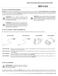
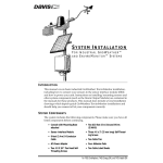
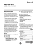
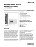
1
SUB Series Interval Data Recorders
INSTALLATION MANUAL
PRE-INSTALLATION
INFORMATION
The SUB Series Interval Data Recorder (IDR) is an energy
data collection device. Installation must be performed by
qualified personnel only and must be in accordance with local
and national electrical codes. Honeywell and its
representatives are not responsible for damage or injury from
improper installation.
The IDR is contained within a NEMA 12 enclosure and is
designed for INDOOR USE ONLY, where ambient
temperatures are between +32 and +120 ºF. It is available in 8
and 16 input configurations.
The SUBIDR must be located in an area that is central to the
meters connected to it.
NOTE: IDRs with modular jacks can be powered from either
the first Honeywell meter or by an external power
supply (requires 120 VAC). IDRs with removable
screw-type connectors require an external power
supply (provided).
SUBIDR-16’s are supplied with an ID letter for each group of 8
inputs to make them compatible with E-Mon Energy™
software. The available choices are A-B, C-D, E-F, G-H, I-J, KL, M-N, O-P, Q-R, S-T, U-V, W-X and Y-Z. No other combinations are available. When mixing 8-point and 16-point IDRs
together, it may be necessary to jump a letter in the system.
As an example, if you have an 8-point IDR labeled “A”, “B” and
“C”, the 16-point IDR to choose would be the E-F unit.
The IDR is available in three configurations.
1.
IMPORTANT:
The meter that is connected to meter jack #1 on the
IDR must be within 100 feet from the IDR, as it supplies low-voltage power to operate the IDR. All other
meters can be located up to 500 feet from the IDR.
Modular Jacks (SUBIDR-8 and SUBIDR-16): Supplied
with all modular jacks for use only with Honeywell
meters.
NOTE: The IDR with modular jacks is designed to operate
with Honeywell meters only. Terminal input models
can support the monitoring of third-party metering
equipment; contact Honeywell for further information.
The IDR must be installed in a location according to these
guidelines to ensure continued safe, trouble-free operation.
—
—
—
—
Do not install near sensitive radio communication
equipment or receiving antenna systems.
Do not install near high-energy electrical fields such as
those produced by welding equipment or by highpower electrical motors.
Always install in an area that is dry, away from any
potential liquid or chemical splash hazards. Never
install electrical equipment in an area where flammable chemicals or vapors are present.
The IDR enclosure’s door must be kept closed once
installed. Exposing the internal circuits to dust, dirt,
fumes or high humidity can damage the IDR.
Fig. 1. IDR board with modular jacks.
2.
Plug-In Screw-Type Connectors (SUBIDR-8 and
SUBIDR-16): Supplied with all plug-in screw-type connectors for use with third-party meters (electric, gas,
water, etc.) that are provided with a dry contact pulse
output. (Requires external power supply.)
NOTE: All internal circuits are isolated from the AC line.
Fig. 2. IDR with screw-type connectors.
62-0342-01
SUB SERIES INTERVAL DATA RECORDERS
3.
Modular Jacks & Screw-Type Connectors (SUBIDR-16
ONLY): Supplied with 8 modular jacks and 8 screw-type
connectors. Used with a mixture of Honeywell and thirdparty meters. (Requires external power supply.)
Connect this meter to jack #1 on the IDR using an 8conductor flat modular cable. (See Chapter 5.0 if the
IDR has the optional AC adapter.)
3. *All remaining Honeywell meters must be connected to
the meter jacks #2-8 using 6-conductor flat modular
cable.
4. SUBIDR-16 - If the IDR is an SUBIDR-16, connect the
additional meters to Jacks # 9-16 on the option card
using 6-conductor flat modular cable.
5. SUBIDR-8s orSUBIDR-16s supplied with plug-in screw
type connectors can be up to 500 feet from all meters,
and utilize a pair of wires for connecting to the meter
pulse output.
* See Appendix C for items 2 & 3 above.
** For more information on cable assembly, see Appendix A.
Fig. 3. IDR with both types of connectors.
Pulse Output Meters (IDR-ST models only):
1.
MECHANICAL INSTALLATION
2.
IMPORTANT:
THE INTERNAL CIRCUITS OF THE IDR CAN BE
DAMAGED BY ELECTROSTATIC DISCHARGE.
BEFORE REACHING INSIDE THE ENCLOSURE,
DISCHARGE YOURSELF BY TOUCHING AN
EARTH-GROUNDED OBJECT.
Each meter is interfaced with the IDR through the plugin screw type connectors. Any of the connectors may be
used with #22-14 AWG conductors.
When used with solid-state switches, correct polarity
must be observed in order for that contact to be recognized. COM (or “C”) on the IDR is 12 VDC that must be
connected to the + side of the pulse switch. The return
side of the switch is connected to SIG (or “S”) on the
IDR.
ACCIDENTAL DISCHARGE OF STATIC ELECTRICITY ONTO THE CIRCUIT BOARD CAN RESULT IN:
- LOSS OF STORED DATA
- A SYSTEM LOCK-UP
- PERMANENT DAMAGE TO THE IDR
The IDR is available in two types of enclosure systems:
1.
Stand-Alone IDR (Standard Configuration)
The stand-alone IDR configuration consists of a single
IDR unit. The enclosure should be mounted using the
mounting flanges located at the top and bottom of the
enclosure. The enclosure has three available knockouts
for cable entrance/ exit from the IDR.
CONNECTING METERS TO THE
IDR
Honeywell Meter Connections
Each Honeywell meter has two modular jacks located at
the top of the main circuit board. The jack on the left
(RJ-45, 8-pin), labeled “IDR”, is used to connect the
meter to the IDR. NEVER USE THE 6-PIN JACK
LOCATED ON THE RIGHT SIDE OF THE METER CIRCUIT BOARD TO CONNECT ANY IDR.
* Be sure that one Honeywell meter is located within
100 feet of the IDR. This meter will be used to supply
the low-voltage power necessary to operate the IDR.
62-0342—01
The meter can be up to 500 feet away from the IDR.
In order to connect “third-party” meters such as gas, water or
utility-type meters, the IDR must be ordered with the screw
terminal connectors (designated with the suffix B or C at the
end of the model number) instead of the modular jacks.
NEVER ATTEMPT TO DRILL THROUGH THE
STEEL ENCLOSURE. DOING SO MAY
PERMANENTLY DAMAGE THE ELECTRONIC
CIRCUITRY AND WILL VOID ALL WARRANTIES.
2.
3.
Third-Party Meter Connections
CAUTION
1.
Fig. 4. Observe polarity when using solid-state switches
with pulse output meters.
2
The IDR for third-party metering is always powered by the
optional AC adapter power supply and requires an available
120 VAC receptacle to obtain the power. The receptacle must
not be switched off at any time. See Section 5.0, Optional AC
Adapter.
The input pulses supplied to the IDR must be non-powered,
and they can be either physical (mechanical) contacts or
electronic switches. When electronic switches are used, the
“COM” terminal on the IDR is the “+” output and the “SIG” is
the return from the switch.
The IDR with modular jacks automatically detects when an
Honeywell meter is connected to it so that it can be
recognized by the software when the meters are added or
SUB SERIES INTERVAL DATA RECORDERS
—
removed. The third-party meter IDR uses a DIP switch to
perform this function. This switch is preset at the factory and
requires no further adjustment.
3.
D7 (Low Battery) -> This LED must be OFF. This
LED indicates a low or missing battery.
—
D6 (System Error) -> This LED must be OFF.
Meter pulse indicators
—
Yellow LEDs P1 through P8 may be flashing.
These LEDs indicate each meter’s pulse rate.
The flash rate depends on how much load the
meter is measuring. The faster the pulse the
greater the load.
IMPORTANT:
IF THE METER MEASURES ZERO LOAD, THERE
IS NO METER PULSE, WHEN THE PULSE RATE
IS ZERO THE YELLOW LED INDICATOR WILL
REMAIN EITHER ON OR OFF UNTIL THERE IS A
LOAD.
NOTE: If one of the LEDs does not flash, verify the meter
connection first. If the meter is properly connected,
check the meter’s display for a flashing load indicator.
4.
Fig. 5. Overview of main circuit board.
MAIN CIRCUIT BOARD VISUAL
CHECKS
Once you have connected meter #1 to jack #1 in the IDR, the
IDR should be energized. If the IDR is not energized, verify:
1.
2.
3.
4.
Meter #1 is turned on. (Meter #1 powers the IDR; if
Meter #1 is not installed and powered up, the IDR will
not function.)
Verify that JMP8 on the IDR circuit board has a jumper
installed.
Verify that J23 & J24 on the IDR circuit board are set in
the position labeled “MTR”. Both jumpers should be set
to the RIGHT position.
Verify that the cable between Meter #1 and Jack #1 on
the IDR is properly assembled. (See Appendix A for
cable assembly.)
NOTE: If the IDR is being powered by the optional AC
adapter instead of by Meter #1, see Section 5.0.
2.
OPTIONAL AC ADAPTER
(OPTIONAL EXTERNAL 120 VAC
POWER SUPPLY)
If you are NOT using the optional AC adapter to power the
IDR, proceed to Section 6.0.
Instead of powering the IDR using Meter #1, Honeywell can
supply an optional AC adapter. If the IDR was provided with
this option, verify the following:
Verify the status of the LED indicators on the IDR circuit
board. (See Appendix B for locations.)
1.
5.
Panel Indicators
—
Two LEDs are visible through the window on the
door of the stand-alone enclosure. THESE LEDS
ARE NOT PRESENT IN MMU STYLE IDRS.
—
Green LED (Power Indicator) -> The green LED
indicates that power is present at the IDR.
—
Red LED (Tamper Alarm) -> The red LED indicates that the IDR door has been opened. This
tamper alarm LED will be on when the door is
closed, and will flash when the door is open.
When the software startup is performed, the IDR
will be initialized by the E-Mon Energy software
and the alarm LED will turn off as long as the door
remains closed. The alarm can only be reset
through the software.
IDR 16 Option 16 Card (applies only to the SUBIDR-16
model.)
—
For each meter (9-16) installed on the options
card, another set of yellow LEDs (P9-P16) will be
present. These LEDs indicate the meter pulse
rate for meters #9 through #16.
Power Supply Indicators
—
L3, green -> This LED is ON.
—
L1, green -> This LED is ON.
System status indicators
—
D4 (CPU), red -> This LED flashes once per second. If D4 flashes twice per second, the IDR is not
initialized. This will be addressed later using EMon Energy software.
3
1.
2.
3.
4.
Jumpers J23 & J24 on the IDR circuit board are set to
the LEFT position (position labeled “EXT”.)
Jumper at JMP8 MUST be removed.
The AC adapter’s two-wire cord must be plugged into
the IDR at TB9. (The polarity of these wires does not
matter.)
Plug the AC adapter into a 120 VAC outlet.
62-0342—01
SUB SERIES INTERVAL DATA RECORDERS
METHOD 1: MODULAR PLUG METHOD
This method requires using 4 stranded conductors inside a
cable that is fitted with an RJ-11 type plug for 4-conductor
modular systems at each end of the cable.
IMPORTANT:
The AC adapter is designed to be used with a 120
VAC outlet only.
5.
The IDR should now be energized. Perform the visual
checks outlined in section 4.
* Do not use any pre-made telephone cables. See Appendix A
for correct cable configuration.
NOTE: The AC adapter provides an isolated 18 VAC/300
mA power source for the IDR.
1.
SERIAL COMMUNICATIONS
2.
Hardwired System using the SUB-RS232K
Communication Key.
(See the hardwired system configuration diagrams in
Appendix F.)
NOTE: The total combined cable length must be no more
than 4,000 feet.
The SUB-RS232K communications key allows you to connect
IDRs to a personal computer that has E-Mon Energy software
installed. The computer communicates with the IDRs through
the SUB-RS232K.
The SUB-RS232K must be located within 15 feet of the host
computer.
The SUB-RS232K is supplied with:
2.
3.
3.
Each IDR has two LEDs (yellow and green) located
directly below the RS-485 jacks. If the system is properly wired, these two LEDs will normally be OFF. These
LEDs will flash when the computer and IDR are communicating.
METHOD 2: TERMINAL BLOCK METHOD
IDRs may also be daisy-chained using a 3-conductor cable.
Instead of using the two modular jacks for the RS-485 daisy
chain, you can use J20 at the bottom right corner of the IDR
circuit board.
Connecting the SUB-RS232K to the
computer
1.
Plug the 4-wire RJ-11 cable/plug assembly into Channel
A on the SUB-RS232K. Connect the other end of this
cable to the IDR at either of the two RS-485 ports at the
top left of the IDR circuit board.
The unused RS-485 port is used to connect another
cable to the next IDR. This is called a “daisy-chain” connection. This can be done repeatedly to connect as
many as 52 individual IDRs.
• (1) 8-conductor cable fitted with RJ-45 plugs
• (1) DB-9 serial COM port adapter
• (1) AC adapter that converts 120 VAC into the 7 VAC
used to power the SUB-RS232K.
Connect the 8-conductor cable to the left-side jack
(labeled “RS232”) on the rear panel of the SUBRS232K.
Connect the appropriate COM port adapter (DB-9) to
the serial port on the back of the computer. Plug the 8conductor cable from the SUB-RS232K into the COM
port adapter.
Connect the 7 VAC AC adapter into the rear panel input
on the SUB-RS232K. Plug the adapter into a 120 VAC
outlet. On the front panel of the SUB-RS232K, two
LEDs will light up (POWER ON and AC ON.)
Remove this 3-terminal plug to facilitate attaching the wires
using the screw terminals that are captivated within the plug
housing.
1.
1. Daisy-chain the IDRs by connecting:
• All HI terminals together
• All LO terminals together
• All GND terminals together
** This requires putting two wires into each of the 3 terminals.
2. Connecting to the SUB-RS232K.
You will need to attach an RJ-11 modular plug to the cable that
serves the RS-485 system.
On each channel on the back of the SUB-RS232K, the pin out
for each channel is as follows:
NOTE: When E-Mon Energy software is accessed on the
computer, a third LED will turn on. The SUB-RS232K
READY indicator will light up as soon as the E-Mon
Energy software is booted up and the correct COM
port is set up via the settings provided in the software’s Locations menu.
Connecting IDRs to the SUB-RS232K using
RS-485
On the rear panel of the SUB-RS232K, there are three jacks
labeled as channels A, B and C. These are RS-485 serial
communications ports used to connect the IDRs. Each of
these three channels can be connected to as many as 52
individual IDRs over a total cable distance of 4000 feet.
Channels are independent and must not be connected to
each other. (See Appendix F.)
62-0342—01
Fig. 6. SUB-RS232K modular jack pin out.
•
•
•
•
PIN1 - Not used
PIN2 - GND
PIN3 - HI
PIN4 - LO
NOTE: It is okay to use the J20 with the modular jacks if
needed.
This completes the installation of the IDR hardwired system.
4
SUB SERIES INTERVAL DATA RECORDERS
Using the USB connection on your
computer
As an alternative to the SUB-RS232K converter, we offer the
SUB-USBK that allows you to convert the RS485 output from
your IDRs for direct connect to your USB connection on your
computer.
APPENDIX A - CABLE
CONFIGURATION
A. Four-Conductor Cables (IDR RS-485 Communication)
Baud Rate Selection
The communication baud rate is selected by means of a
jumper on the circuit board (See appendix C for location.)
There are three (3) selections: 19200, 9600 (factory default)
and 2400.
1.
2.
3.
4.
When using the IDR with a modem, the rate of 9600
should always be selected.
The baud rate on the IDR must always match the baud
rate selected in the E-Mon Energy software. Communication will not work if they are not set correctly.
After a baud rate change, press CPU Reset (See
Appendix C) to register the change in the IDR.
All IDRs in the “daisy chain” circuit must be set at the
same baud rate.
Fig. 7. connectors.
B. Six-Conductor Cables (Meters #2-#8, optional #9-#16)
Fig. 8. connectors.
C. Eight-Conductor Cables (Meter #1, RS-232 Key to
Computer)
Fig. 9. connectors.
NOTE: All cables are wired pin-to-pin (straight through) as
shown above.
5
62-0342—01
SUB SERIES INTERVAL DATA RECORDERS
APPENDIX B - LED INDICATORS
D7-Clear Red LED
Low Battery
MUST be "OFF"
(Indicates low battery
when lit)
L1-Green LED
Serial Communications
Power Supply
Always "ON"
(Indicates power supply
is okay if LED is ON)
D4-Red LED
CPU Status
Flashes once per
second
D6-Clear Red LED
System Error
Always "OFF" when
system is operating
normally
D1-Green LED
D2-Yellow LED
See "Serial
Communications"
P1-P8-Yellow LED
Meter Pulse Indicators
(Indicates input pulses
being received from
meters)
L3-Green LED
Main Power Indicator
Always "ON"
Fig. 10. LED indicators.
62-0342—01
6
SUB SERIES INTERVAL DATA RECORDERS
APPENDIX C - IDR CIRCUIT BOARD COMPONENTS
Battery
J3-J4-RS-485 Communications Jacks
See "Serial Communications"
(Ports used to connect one IDR
to another IDR or Key)
CPU Reset Button
Baud Rate Selection
See "Serial
Communications"
(Selects communication
baud rate ALWAYS set at
9600 BPS when modem
is present)
Baud Rate Selection
See Chapter 6
d"Communications"
JMP-8-Meter Power Selection
See “Main Circuit Board
Visual Checks” and “Optional
AC Adapter”
(Selects external power, or
powered from Meter #1)
M1-M8-Meter Inputs
(Ports used to connect
meters to IDR)
J20-RS485
Communications
See "Serial Communications"
TB9-External Power Input
See “Optional
AC Adapter”
(Connects external
power supply adapter)
J23 & J24-Input Power
Selection
See “Main Circuit
Board Visual Checks” and
“Optional AC Adapter”
Fig. 11. IDR circuit board components.
7
62-0342—01
SUB SERIES INTERVAL DATA RECORDERS
APPENDIX D - SYSTEM WIRING GUIDES
Wiring Guide for SUBIDR-8
DB-9 (DTE) Connector
RJ-45
SUB-RS232K
PC
RJ-11
6' cable provided by
Honeywell (15 ft max.)
8-conductor cable
& modular plug
AC Adapter
4-Conductor
Flat Modular Cable
Up to 4000 Feet Total
Daisy-Chain or
Star Connection
Channel 1 of 3
IDR A
(One of three channels shown for clarity.)
(Up to 8 Meters)
8-Cond.
RJ-45
6-Cond.
RJ-45
6-Cond.
RJ-45
RJ-11
Up to 52 SUBIDR-8s per channel
~
~
(Up to 8 Meters)
IDR Z
CONNECTION
CABLE TYPE
CONNECTOR
SUBIDR to Honeywell Meter #1
8-cond. 22-26 AWG
flat modular cable
RJ-45
SUBIDR to Honeywell Meters #2-8
6-cond. 22-26 AWG
(Pins 1 & 8 not used)
RJ-45
RJ-11
SUBIDR to SUBIDR
4-cond. 26 AWG
SUBIDR to SUB-RS232K
4-cond. 26 AWG
RJ-11
SUB-RS232K to Computer *
8-cond. 22-26 AWG
flat modular cable
RJ-45/DTE
SUB-RS232K to Modem *
8-cond. 22-26 AWG
flat modular cable
RJ-45
SUBIDR to SUB-USBK *
Allows connection directly
to the computer USB
SUBIDR to Pulse Meter
2-cond. 14-22 AWG
Note: Meter 1 must be installed within
100 feet of IDR. Meters 2-8 must be installed
within 500 feet of IDR.
* Supplied by Honeywell
Note: When constructing field-installed cables, modular cables must be made
so that the individual wires go through on the same pin number.
Fig. 12. Wiring overview for SUBIDR-8.
62-0342—01
8
SUB SERIES INTERVAL DATA RECORDERS
Wiring Guide for SUBIDR-16
DB-9 (DTE) Connector
RJ-45
SUB-RS232K
PC
RJ-11
6' cable provided by
Honeywell (15 ft max.)
8-conductor cable
& modular plug
AC Adapter
4-Conductor
Flat Modular Cable
Up to 4000 Feet Total
Daisy-Chain or
Star Connection
Channel 1 of 3
IDR A-B
(One of three channels shown for clarity.)
(Up to 16 Meters)
8-Cond.
RJ-45
6-Cond.
RJ-45
6-Cond.
RJ-45
RJ-11
Up to 26 SUBIDR-16s per channel
(3 channels per SUB-RS232K)
~
~
(Up to 16 Meters)
IDR Y-Z
3rd
Party
Meter
CONNECTION
CABLE TYPE
CONNECTOR
SUBIDR to Honeywell Meter #1
8-cond. 22-26 AWG
flat modular cable
RJ-45
SUBIDR to Honeywell Meters #2-16
6-cond. 22-26 AWG
(Pins 1 & 8 not used)
RJ-45
SUBIDR to SUBIDR
4-cond. 26 AWG
RJ-11
IDR to RS-232 Key 2000
4-cond. 26 AWG
RJ-11
SUB-RS232K to Computer *
8-cond. 22-26 AWG
flat modular cable
RJ-45/DTE
SUB-RS232K to Modem *
8-cond. 22-26 AWG
flat modular cable
RJ-45
SUBIDR to SUB-USBK *
Allows connection directly
to the computer USB
SUBIDR to Pulse Meter
2-cond. 14-22 AWG
3rd
Party
Meter
Pair of wires
(#22-#14 AWG)
3rd
Party
Meter
Note: Meter 1 must be installed within
100 feet of IDR. Meters 2-8 must be installed
within 500 feet of IDR.
* Supplied by Honeywell
Note: When constructing field-installed cables, modular cables must be made
so that the individual wires go through on the same pin number.
Fig. 13. Wiring overview for SUBIDR-16.
9
62-0342—01
SUB SERIES INTERVAL DATA RECORDERS
APPENDIX E - HARDWIRED SYSTEM CONFIGURATION DIAGRAMS
SUBIDR-8, Using Honeywell Meters:
IDR
Up to 8 Meters
Up to 4000 Feet Total
Channel 1
Up to 52
SUBIDR-8’s
~
~
IDR
PC
Up to 8 Meters
RS-232 Serial Port
COM1 - COM4
15’ max
Channel 2
SUB-RS232K*
IDR
AC Adapter
Channel 3
Up to 8 Meters
Up to 4000 Feet Total
Up to 52
SUBIDR-8’s
~
~
IDR
NOTE:
Up to 8 Meters
Meter #1 must be installed within 100 feet of IDR.
Meters #2-16 must be installed within 500 feet of IDR.
Meter #1 uses 8-conductor cable.
Meters #2-16 use 6-conductor cable.
Fig. 14. Hard-wiring the SUBIDR-8.
62-0342—01
10
SUB SERIES INTERVAL DATA RECORDERS
SUBIDR-16, Using Honeywell Meters
IDR
Up to 16 Meters
Up to 4000 Feet Total
Channel 1
~
~
Up to 26
SUBIDR-16’s
IDR
Up to 16 Meters
PC
RS-232 Serial Por t
COM1 - COM4
Channel 2
SUB-RS232K*
6' cable provided by
Honeywell (15 ft max.)
IDR
AC Adapter
Channel 3
Up to 16 Meters
Up to 4000 Feet Total
Up to 26
SUBIDR-16’s
~
~
IDR
NOTE:
Up to 16 Meters
Meter #1 must be installed within 100 feet of IDR.
Meters #2-#16 must be installed within 500 feet of IDR.
Meter #1 uses 8-conductor cable.
Meters #2-16 use 6-conductor cable.
SUBIDR-16, Using Other Utility-Type Meters
(Gas, Water , Etc.)
IDR
Up to 16 Meters
AC Adapter
Up to 4000 Feet Total
Channel 1
~
~
Up to 26
SUBIDR-16’s
IDR
Up to 16 Meters
PC
RS-232 Serial Por t
COM1 - COM4
AC Adapter
Channel 2
SUB-RS232K*
6' cable provided by
Honeywell (15 ft max.)
IDR
AC Adapter
AC Adapter
Channel 3
Up to 16 Meters
Up to 4000 Feet Total
Up to 26
SUBIDR-16’s
~
~
IDR
Up to 16 Meters
AC Adapter
NOTE:
Meters must be installed within 500 feet of IDR.
Meter connected with a pair of #22-#14 AWG conductors.
Fig. 15. Hard-wiring the SUBIDR-16.
11
62-0342—01
SUB SERIES INTERVAL DATA RECORDERS
APPENDIX G - IDR TECHNICAL SPECIFICATIONS
Enclosure:
Lockable steel JIC box NEMA 12.
Dimensions:
9.5” H x 6.75” W x 3.875” D.
Knockouts:
Three (3) on bottom of enclosure (3/4” Cond.)
Power Supply:
Powered by meter or optional 120 VAC adapter.
Back Up:
Lithium Power Cell LTC-3PN (10 year lifetime)
LED Indicators:
Input pulse, CPU operation, alarm, power, communication
Inputs
SUBIDR-8:
Eight (8) eight-pin modular ports
or
Eight (8) 2-screw plug-in terminals
SUBIDR-16:
Sixteen (16) eight-pin modular ports
or
Sixteen (16) 2-screw plug-in terminals
or
Eight (8) eight-pin modular ports and eight (8) 2-screw plug-in terminals
Max Pulse Input:
<600 pulses per minute (50% duty cycle)
Data Storage:
12 days @ 5-minute sampling intervals
36 days @ 15-minute sampling intervals
Interface with:
Honeywell submeters, Electric utility meters, third-party submeters, gas meters, water meters, BTU meters and any meter
equipped with a contact pulse output (using available 2-screw terminals.)
Power Consumption:
2 watts maximum, 1.2 watts typical
Processor:
8-bit; 14 MHz main clock
Real-Time Clock:
100-year clock/calendar. Automatically makes changes to standard/daylight savings time.
Communications:
Serial, RS-485, 3-wire. Optically isolated from all other circuits. 9600 bps standard; provisions for 19200 or 2400 bps.
62-0342—01
12
SUB SERIES INTERVAL DATA RECORDERS
LIMITED WARRANTY
accident or the negligence of any party; (iv) damaged as a
result of events beyond Honeywell’s control or other force
majeure events or (v) used in conjunction with equipment,
components, accessories, parts or materials not supplied or
approved by Honeywell.
Subject to the exclusions listed below, Honeywell will either
repair or replace (at its option) any product that it
manufactures and which contains a defect in material or
workmanship.
The following exclusions apply:
1. This Limited Warranty is only effective for a period of (18)
eighteen months following the date of manufacture when
installed in accordance with manufacturer’s instructions by
qualified personnel.
2. Honeywell must be notified of the defect within ninety (90)
days after the defect becomes apparent or known.
3. Buyer’s remedies shall be limited to repair or replacement
of the product or component which failed to conform to
Honeywell’s express warranty set forth above.
4. Buyer shall be responsible for all freight costs and shall
bear all risk of loss or damage to returned goods while in
transit.
5. This Limited Warranty does not cover installation, removal,
reinstallation, or labor costs, and excludes normal wear and
tear. Buyer shall provide labor for the removal of the defective
component or item and installation of its replacement at no
charge to Honeywell.
6. This Limited Warranty does not cover any product if: (i) a
product is altered or modified from its original manufactured
condition, (ii) any repairs, alterations or other work has been
performed by Buyer or others on such item, other than work
performed with Honeywell’s authorization and according to its
approved procedures; (iii) the alleged defect is a result of
abuse, misuse, improper maintenance, improper installation,
13
7. This Limited Warranty is limited to the obligation to repair or
replace the manufactured product. This is the sole and
exclusive remedy for any breach of warranty. IN NO EVENT
SHALL HONEYWELL BE LIABLE FOR ANY INDIRECT,
INCIDENTAL, SPECIAL, CONSEQUENTIAL OR PUNITIVE
DAMAGES (INCLUDING ANY DAMAGE FOR LOST
PROFITS) ARISING OUT OF OR IN CONNECTION WITH
THE FURNISHING OF PRODUCTS, PARTS OR SERVICES,
OR THE PERFORMANCE, USE OF, OR INABILITY TO USE
ANY PRODUCTS, PARTS OR SERVICES, SALE OF OR
OTHERWISE, WHETHER BASED IN CONTRACT,
WARRANTY, TORT, INCLUDING WITHOUT LIMITATION,
NEGLIGENCE, OR ANY OTHER LEGAL OR EQUITABLE
THEORY.
8. EXCEPT AS EXPRESSLY PROVIDED HEREIN,
HONEYWELL MAKES NO WARRANTY OF ANY KIND,
EXPRESS OR IMPLIED WITH RESPECT TO ANY
PRODUCTS, PARTS OR SERVICES PROVIDED BY
HONEYWELL INCLUDING, BUT NOT LIMITED TO, THE
IMPLIED WARRANTIES OF MERCHANTABILITY AND
FITNESS FOR A PARTICULAR PURPOSE. PRODUCTS OR
COMPONENTS DISTRIBUTED, BUT NOT
MANUFACTURED, BY HONEYWELL ARE NOT
WARRANTED BY HONEYWELL AND BUYER MUST
INSTEAD RELY ON THE REPRESENTATIONS AND
WARRANTIES, IF ANY, PROVIDED DIRECTLY TO THE
BUYER BY THE MANUFACTURER OF SUCH PRODUCT
OR COMPONENT.
62-0342—01
SUB SERIES INTERVAL DATA RECORDERS
62-0342—01
14
SUB SERIES INTERVAL DATA RECORDERS
15
62-0342—01
SUB SERIES INTERVAL DATA RECORDERS
Automation and Control Solutions
Honeywell International Inc.
1985 Douglas Drive North
Golden Valley, MN 55422
Honeywell Limited-Honeywell Limitée
35 Dynamic Drive
Toronto, Ontario M1V 4Z9
www.honeywell.com/buildingsolutions
® U.S. Registered Trademark
© 2011 Honeywell International Inc.
62-0342—01 M.S. 02-11
Printed in U.S.A.