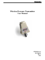
1
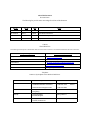
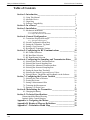
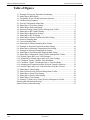
Wireless Pressure Transmitter
User Manual
XYR 5000 Line
34-XY-25-01
Rev. 3
11/04
User Manual
Honeywell Industrial Wireless
Wireless Pressure Transmitter
Wireless Temperature Transmitter
Models WG51x and WA51x
Versions 1.57 or later
!
•
•
•
•
•
•
•
Important Information to the User
Changes or modifications not expressly approved by the manufacturer may void
the user’s authority to operate the equipment.
This device complies with Part 15 of the FCC Rules. Operation is subject to the
following two conditions: 1) this device may not cause harmful interference, and
2) this device must accept any interference received, including interference that
may cause undesired operation.
This device is for mobile and fixed use only (not portable or body-worn). A
separation distance of 20cm must be maintained at all times between the antenna
and the body of the user and bodies of nearby persons.
If the Wireless Management Toolkit (RF Server) software is shutdown, the RS485 network MUST be physically disconnected from the PC as the serial port is
no longer being controlled by the software and may disrupt communications
between the Base Radio(s) and Analog/Digital Output Module(s).
This device has been designed to operate with an antenna having a maximum
gain of 9 dBd. Antenna having a higher gain is strictly prohibited per regulations
of Industry Canada. The required antenna impedance is 50 ohms.
To reduce potential radio interference to other users, the antenna type and its gain
should be so chosen that the equivalent isotropically radiated power (EIRP) is not
more than that required for successful communication.
The installer of this radio equipment must ensure that the antenna is located or
pointed such that it does not emit RF field in excess of Health Canada limits for
the general population; consult Safety Code 6, obtainable from Health Canada’s
website www.hc-sc.gc.ca/rpb.
!
•
•
FCC Certification
2500 West Union Hills Drive
!
This product is a frequency hopping RF transceiver module for the 900MHz ISM
band, designed to meet FCC 15.247, and is used in industrial control and monitoring applications.
The antenna is factory installed and MUST NOT be removed or modified by
user.
Honeywell Inc.
Industrial Measurement and Control
!
Copyright 2004 by Honeywell International Inc.
Rev. 3– 11/28/2004
While this information is presented in good faith and believed to be accurate, Honeywell disclaims the implied warranties of merchantability and
fitness for a particular purpose and makes no express warranties except as may be stated in its written agreement with and for its customers.
In no event is Honeywell liable to anyone for any indirect, special or consequential damages. The information and specifications in this document
are subject to change without notice.
Phoenix, AZ 85027
Honeywell® and TotalPlant ® are U.S. registered trademarks Of Honeywell International Inc.
Other brand or product names are trademarks of their respective owners.
Rev. 3
11/04
User Manual
I
About This Document
Revision Notes
The following list provides notes concerning all revisions of this document.
Rel ID
Doc ID
Date
Notes
34-XY-25-01
Rlse. 0
12/03
1st issue of document.
34-XY-25-01
Rev. 1
02/04
2nd issue of document.
34-XY-25-01
Rev. 2
09/04
Reformatted layout, updated technical information.
34-XY-25-01
Rev. 3
06/04
Updated maintenance section
Contacts
World Wide Web
The following lists Honeywell’s World Wide Web sites that will be of interest to our industrial automation and control customers.
Honeywell Organization
WWW Address (URL/e-mail)
Corporate
http://www.honeywell.com
Industrial Measurement and Control
http://content.honeywell.com/imc/
International
http://www.honeywell.com/Business/global.asp
Field Instruments
http://www.honeywell.com/imc
Technical Assistance Center
[email protected] (e-mail)
Telephone
Contact us by telephone at the numbers listed below.
Organization
United States and Canada
Phone Number
Honeywell Inc.
Industrial Automation and Control
1-800-343-0228
1-800-525-7439
Global Technical Support Center
1-800-423-9883
Asia Pacific
Honeywell Asia Pacific Inc.
Hong Kong
(852) 8298298
Europe
Honeywell PACE
Brussels, Belgium
[32-2] 728-2111
Latin America
Honeywell Inc.
Sunrise, Florida U.S.A.
(305) 364-2355
Sales
Service
Honeywell Industrial Wireless
Wireless Pressure Transmitter
Table of Contents
Section 1: Introduction____________________________________1
1.1: Using This Manual
1.2: About the Device
1.3: Unpacking
1.4: Software Compatibility
1
2
2
2
Section 2: In a Hurry? ____________________________________3
Section 3: Installation_____________________________________4
3.1: Mechanical Installation
3.1.1: Transmitter Positioning
3.1.2: Simple RF Placement Procedure
4
4
5
Section 4: General Configuration ___________________________7
4.1: Transmitter Displayed Messages
4.1.1: The Read-Only Sequence
4.2: Overall Configuration Menu Map
4.3: Setting the Transmitter Tag Name
4.4: Setting a User Password
4.5: Resetting All Transmitter Settings
7
7
8
8
9
9
Section 5: Configuring the RF Communications ______________10
5.1: RF Channel Selection
5.2: RF Baud Rate Selection
5.3: RF Identification Selection
10
10
11
Section 6: Configuring the Sampling and Transmission Rates ___12
6.1: Selecting the Normal Transmission Rate
6.2: Selecting the Normal Sampling Rate
6.3: Selecting the Abnormal Transmission Rate
6.4: Selecting the Abnormal Sampling Rate
6.5: Setting the Smart Rate Threshold
6.6: Selecting the Normal Upper and Lower Values
6.7: Selecting Rates, Thresholds, and Deadbands via the Software
12
13
14
15
16
17
18
Section 7: Configuring the Process Variable __________________19
7.1: Selecting the Units of Measure
7.2: Zeroing the Sensor
7.3: Setting a Measurement Offset
7.4: Trimming the Measurement
7.5: Entering a 22-Point Curve
19
20
20
21
21
Section 8: Maintaining the Transmitter _____________________22
8.1: Changing the Battery
22
Section 9: Technical Specifications _________________________23
Dimensioned Mechanical Drawing
Intrinsic Safety Control Drawing
24
25
Appendix A: Navigating the Menus ________________________26
Appendix B: Displayed Message Definitions _________________27
Appendix C: Transmitter Menu Map _______________________28
Rev. 3
11/04
User Manual
III
Honeywell Industrial Wireless
Wireless Pressure Transmitter
Table of Figures
3.1: Example of Incorrect Transmitter Positioning .................................................. 4
3.2: Menu Map to RSSI Mode.................................................................................. 5
4.1: Transmitter Power-UP and Operations Sequence ............................................. 7
4.2: The Read-Only Sequence .................................................................................. 7
4.3: Overall Configuration Menu Map ..................................................................... 8
4.4: Menu Map to Tag Name Setting ....................................................................... 8
4.5: Menu Map to Password Setting......................................................................... 9
4.6: Password Setting Using Wireless Management Toolkit ................................... 9
5.1: Menu Map to RF Channel Setting................................................................... 10
5.2: Menu Map to Baud Rate Setting ..................................................................... 10
5.3: Menu Map to RF ID Setting............................................................................ 11
6.1: Menu Map to Normal Transmission Rate Setting........................................... 12
6.2: Incorrect Sampling Rate .................................................................................. 13
6.3: Correct Sampling Rate .................................................................................... 13
6.4: Menu Map to Normal Sampling Rate Setting ................................................. 13
6.5: Example of Abnormal Transmission Rate Setting .......................................... 14
6.6: Menu Map to Abnormal Transmission Rate Setting....................................... 14
6.7: Example of Abnormal Sampling Rate Setting ................................................ 15
6.8: Menu Map to Field Abnormal Sampling Rate Setting.................................... 15
6.9: Smart Rate Configuration Using Wireless Management Toolkit.................... 16
6.10: Normal Upper and Lower Value Example.................................................... 17
6.11: Menu Map to Normal Upper and Lower Value Settings .............................. 17
6.12: Condition “Chatter” Without Time Deadband .............................................. 17
6.13: Condition “Chatter” Elimination Due to Time Deadband ............................ 17
6.14: Sampling and Transmission Rate Selection Using the Software .................. 18
6.15: Normal Upper and Lower Value Selection Using the Software ................... 18
7.1: Menu Map to Units Setting ............................................................................. 19
7.2: Units Selection Using Wireless Management Toolkit .................................... 19
7.3: Menu Map to Sensor Zero Setting................................................................... 20
7.4: Menu Map to Sensor Offset Setting ................................................................ 20
7.5: Menu Map to Trim Setting.............................................................................. 21
7.6: Setting a 22-Point Curve Using Wireless Management Toolkit ..................... 21
Dimensioned Mechanical Drawing ........................................................................ 24
Intrinsic Safety Control Drawing ........................................................................... 25
IV Rev. 3
11/04
User Manual
Honeywell Industrial Wireless
Wireless Pressure Transmitter
Section 1: Introduction
1.1: USING THIS MANUAL
This manual is designed to assist in installing, operating, and maintaining
Honeywell Model WG51x and WA51x Pressure Transmitters. The manual is broken into sections as follows:
Section 2: In a Hurry?
This section summarizes what must be done in order to get the device installed, configured and in operation quickly. However, it does not provide
detailed or how-to information to perform the tasks outlined.
Section 3: Installation
This section explains mechanical installation considerations; such as
Transmitter placement and Transmitter Mounting.
Section 4: General Configuration
In this section general configuration options such as password protection,
and selecting a user password are discussed. Also covered, is the setting of
a Transmitter tag name, resetting of all Transmitter settings, and a discussion of the various messages that are displayed on the Transmitter LCD.
Section 5: Configuring the RF Communications
This section covers the setup of the Transmitter RF Communications
which allow the Transmitter to achieve communication with the Base Radio. Parameters discussed are the Transmitter RF ID, the RF channel setting and Baud Rate.
Section 6: Configuring the Sampling and Transmission Rates
This section aids the user in selecting the amount of time between each
sample of the process, and the time between each transmission of this
sample to the Base Radio. Also discussed is the use of setting an abnormal
threshold in which sampling and transmission times may change during a
period when the process variable is within the abnormal region.
Section 7: Configuring the Process Variable
This section helps the user in the selection of engineering units, as well as
discussing the zeroing of the sensor, setting of a measurement offset, and
trimming the process measurement.
Section 8: Maintaining the Transmitter
This section explains how the Transmitter should be cared for once it has
been placed into service. Changing the battery is also covered in this section.
Section 9: Technical Specifications
This section explains the technical specifications that are associated with
this device such as power characteristics, accuracy, and operating characteristics.
Rev. 3
11/04
User Manual
1
Honeywell Industrial Wireless
1.2: ABOUT THE DEVICE
Wireless Pressure Transmitter
The Honeywell Pressure Transmitter is a reliable Radio Frequency (RF)
transceiver coupled with an pressure sensor that can be used to monitor a
variety of processes in hazardous and hard-to-reach areas. The time and
expense of running wires often makes it difficult to measure parameters
that have an economic impact on your plant operation, but the Pressure
Transmitter allows you to quickly and accurately monitor those devices at
fraction of the cost, which gives you bigger and faster returns on your
instrumentation investments.
The Transmitters communicate in a secure, digital protocol over a band of
frequencies from 902MHz to 928MHz. This data communication technique has been the backbone of the military’s secure communications protocols for many years. These devices require no wires, permits or licenses,
and they are easily set up and installed right out of the box.
You can use this device for long term monitoring in remote locations, for
short-term data gathering on process conditions, or to quickly test the economic viability of a new installation.
The purpose of this manual is to help you install and maintain your Honeywell Pressure Transmitter. BEFORE setting up and installing the Transmitter please setup and configure the Base Radio.
1.3: UNPACKING
Remove the Packing List and check off the actual equipment received. If
you have any questions on your shipment, please call your Honeywell
Representative. Upon receipt of shipment, inspect the container for any
signs of damage in transit. Especially take note of any evidence of rough
handling. Report any apparent damage immediately to the shipping agent.
Please note that sometimes units are assembled with accessories when
shipped. Inspect the shipment carefully if you think that something is
missing. This is rare, as we take considerable care to pack units for shipment, but it does sometimes happen. Please give us a call and we may be
able to resolve this matter quickly over the phone.
NOTE
Please note that the carrier will not honor any claims for damage unless
all shipping materials are saved for their examination. If damage is found
during examining and removal of the contents, save the packing material
and the carton.
1.4: SOFTWARE
COMPATABILITY
Software for Honeywell is revised periodically. Internal device software
may contain portions that are not compatible with previous versions of the
Wireless Management Toolkit software.
To ensure software compatibility, Wireless Management Toolkit software
version 1.56.126 or later must be used. If you believe you are experiencing software compatibility issues please call Honeywell Technical Support
at 800-423-9883 or email [email protected].
2 Rev. 3
11/04
User Manual
Honeywell Industrial Wireless
Wireless Pressure Transmitter
Section 2: In a Hurry?
This section summarizes what must be done in order to get the device installed, configured and in operation quickly. However, it does not provide
detailed or how-to information to perform the tasks outlined.
1. Place the Transmitter in the desired location of operation.
Note: Trimming and zeroing of the measurement may be necessary before device can be placed in service. If trimming is required perform steps 7 -14 prior to placing device in service.
2. Ground Transmitter via conduit or bonding strap
3. Turn on Transmitter by pressing ENTER and NEXT buttons simultaneously and holding until unit powers up.
4. Set RF CHAN setting equal to the Base Radio’s RF Channel.
5. Set BAUD RT setting equal to the Base Radio’s Baud Rate.
6. Set RF ID number to be a unique value between 1 and 50.
7. Select normal transmission rate.
8. Select normal sampling rate.
9. Select abnormal transmission rate.
10. Select abnormal sampling rate.
11. Set normal upper and lower values.
12. Select engineering measurement units.
13. Zero the sensor
14. Trim the sensor
!
Caution
!
If the Base Radio is not energized for more than
30 minutes, the Transmitters should also be turned
off to preserve battery life. Leaving the Transmitters on when the Base Radio is not energized or
out of range will cause the Transmitters to transmit very frequently and drastically reduces their
battery life.
If the “RF OFF” message is being displayed on the Transmitter LCD, perform the following:
•
If a “NO RF” message is being displayed on the Transmitter LCD, check
the following:
•
•
•
•
•
Rev. 3
11/04
Set the Set RF CHAN setting equal to the Base Radio’s RF
Channel.
Is the Transmitter set to the above listed configurations?
Is the Base Radio on?
Are the Transmitter and Base Radio set to the matching configurations? (See Section 5 of Transmitter and Base Radio
User Manuals)
Are the Base Radio and Transmitters unable to communicate
due to obstructions or distance? (See Transmitter Manual:
Transmitter Placement section)
Did you perform the Simple RF Placement Procedure? (See
Transmitter Guide: A Simple RF Placement Procedure section)
User Manual
3
Honeywell Industrial Wireless
Wireless Pressure Transmitter
Section 3: Installation
3.1: Mechanical Installation
!
Warning
!
During installation do not apply force to the instrument housing or antenna. Use a proper wrench
for all installations. Failure to use correct installation procedures can cause damage to the Base
Radio.
In this section mechanical installation instructions are discussed for the
various setup capabilities of the Pressure Transmitter. The subsections are
as follows:
3.1.1: Transmitter Positioning
3.1.2: A Simple RF Placement Procedure
The Honeywell Pressure Transmitter is a rugged device, but it provide
much better performance if installed with careful consideration, as noted
in this manual. It may be utilized in any pressure measurement service so
long as care is exercised to prevent exposing the sensing elements to excess stress or temperature. Installation practices have a lot to do with
these service parameters and the life that you can expect from your Honeywell Pressure Transmitter. The main considerations for installation are
covered below.
Give careful consideration to the environment where you will be installing
your instrument. Avoid installations that expose the device to excess temperature, high vibration, considerable shock, or exposure to dripping condensate or corrosive materials. Also avoid installing the device in an unserviceable location.
Most often these problems can be avoided with some thought at the time
of installation. The practices noted below are generally recommended, but
they can only act as a guideline and cannot cover all possible variations.
The final installation must be made at the discretion and approval of the
user. You must be the judge of the actual installation.
Dimensioned mechanical drawings for aid in mechanical installation are
located in Section 9: Technical Specifications
3.1.1: Transmitter Positioning
Figure 3.1: Examples of Incorrect Transmitter Positioning
Correct positioning of the Transmitter will ensure the best performance of
the device. When planning the positioning of the Transmitters there are a
few parameters that must be paid attention to:
•
Ideally the top of the Transmitter will generally point in an
upward fashion. The bottom of the Transmitter should NOT
point directly at the Base Radio and the Transmitter LCD
should point away from the Base Radio.
•
All Transmitters should maintain an approximate spacing of
at least one foot apart from one another.
•
The line of sight range between a Transmitter and Base Radio is 2000 feet at the 19.2K baud rate setting. Note that this
range is reduced by the amount of RF Noise present, obstructions, and the material properties of the obstruction.
•
Only place the Transmitter in ambient operating temperatures of -40°F to 185°F (-40°C to 85°C).
Figure 3.1, shown to the left, gives examples of incorrect setups according
to the previously mentioned parameters.
Because there are so many setup possibilities we cannot cover them all. A
correct setup would make sure that the above warnings are heeded, and
that the Transmitter and Base Radio are capable of communication. The
RF Placement Test section will help you to determine if you have a selected the correct installation points and orientations for your application.
4 Rev. 3
11/04
User Manual
Honeywell Industrial Wireless
Wireless Pressure Transmitter
3.1.2: A Simple RF Placement Procedure
Remember, proper placement of the Transmitter will optimize your RF
communication range and capabilities. Perhaps the best test to perform
before mechanically mounting the unit is a quick hand-held test.
To perform this test you should have a good idea of where the Base Radio
will be placed (for more information see Section 3 of the Base Radio User
Manual). Put the Base Radio in this area and power it up. Make sure that
the Base Radio and Transmitter are on the same RF Channel and Baud
Rate (See Section 5). You may also have to increment the number of
Transmitters with which the Base Radio is communicating (See the Base
Radio User Manual Section 4.3).
Once both the Base Radio and Transmitter are set up to be on the same
network, make sure communication is established by looking at the Transmitter LCD for the ‘RF OK’ message in the Read-Only Sequence (see
Section 4.1.1).
After communications have been established, Transmitter should be
placed in RSSI Diagnostic mode to determine the signal strength at the
location of the equipment to be monitored. Placing the Transmitter in this
mode is explained in the following section.
3.1.2.1: Transmitter RSSI Diagnostic
The Received Signal Strength Indicator (RSSI), located in the Transmitter’s diagnostic menu, displays the RF signal strength in one of seven
ranges. The signal strength is displayed on the LCD using a combination
of ‘>’ and ‘_’ characters. Full signal strength is displayed as “> > > > > >
>” while minimum signal strength is displayed as “> _ _ _ _ _ _”. If the
Transmitter is not communicating with the Base Radio (i.e. NO RF), all
underscore characters will be displayed (“_ _ _ _ _ _ _”).
The RSSI is measured every time the Transmitter receives a message from
the Base Radio. The signal strength of the received message from the Base
Radio is calculated during this time. The actual signal strength in dBm for
each range is shown below:
>
>
>
>
>
>
>
Less than
Between
Between
Between
Between
Between
Greater
than
-90 dBm &
-85 dBm &
-85 dBm
-80 dBm
-105 dBm & -100 dBm & -95 dBm &
-105 dBm
-100 dBm
-95 dBm
-90 dBm
-80 dBm
To place the Transmitter in RSSI Diagnostic mode follow the menu map
shown on the following page in Figure 3.2. Note that the RSSI menu is
under the DIAGNSE menu and not the CONFIG menu.
Figure 3.2: Menu Map to RSSI Mode
Rev. 3
11/04
User Manual
5
Honeywell Industrial Wireless
3.1.2.1 Continued
Wireless Pressure Transmitter
Now that the Transmitter is in the RSSI mode, bring the Transmitter close
to the equipment you wish to monitor. Look at the LCD; notice the ‘>’
will constantly fluctuate. One should estimate an average value based on
these fluctuations. While the ideal signal integrity is seven arrows, the
suggested fluctuating arrow ranges for the different RF Baud Rate settings
are listed below:
•
•
•
4.8K Baud – between 1 and 4 arrows
19.2K Baud – between 2 and 5 arrows
76.8K Baud – between 3 and 6 arrows
Once you have verified that you are receiving a signal, you should check
to make sure the Transmitter is communicating properly with the Base
Radio. To do so exit the RSSI by pressing ENTER, and then navigate to
the EXIT? of the diagnostic menu and return to the Operations Sequence
shown in Figure 1 on page 8. Once in the Operations Sequence, you will
notice small arrows on the rightmost and leftmost regions of the LCD.
These arrows indicate the sending and receiving of messages between the
Base Radio and the Transmitter. If both arrows are moving up and down,
and you do not see a NO RF message, then the position you have selected
will be suitable for mounting the device.
NOTE
While using slower baud rate increases communication distance, it also requires more time to complete a communications cycle. This may not be
suitable for your application.
If only one or neither of the arrows is moving, and you see a NO RF message, then you do not have satisfactory RF communication with the Base
Radio. If your application allows, move the Transmitter to a different position and check again for communications. If your application only allows
you to mount at this particular point, you may want to try a slower baud
rate setting for an increased range (see note).
One final solution is to reposition the Base Radio. However, this may affect communications with previously installed Transmitters, and if so, may
require the use of a second Base Radio for your application. To select a
better spot for the Base Radio, see section 3.1.1 of the Base Radio User
Manual.
6 Rev. 3
11/04
User Manual
Honeywell Industrial Wireless
Wireless Pressure Transmitter
Section 4: General Configuration
This section discusses the generalities for configuring the Transmitter via
the NEXT and ENTER buttons. The subsections are as follows:
4.1: Transmitter Displayed Messages
4.1.1: The Read-Only Sequence
4.2: The Overall Configuration Menu Map
4.3: Setting a Transmitter Tag Name
4.4: Setting a User Password
4.5: Resetting All Transmitter Settings
4.1: Transmitter Displayed
Messages
To turn the Transmitter on, press both the NEXT and ENTER buttons and
hold them for a few seconds. Upon power up, the Transmitter will display
the Power-Up Sequence, and then go into the Operations Sequence. These
Sequences are shown in Figure 4.1 below:
NOTE
During configuration and testing, keep Transmitters at least one foot apart and away from the Base
Radio to ensure good communications.
Figure 4.1: Transmitter Power-Up and Operations LCD Sequences
4.1.1: The Read-Only Sequence
Once the Transmitter is in the Operations Sequence, a user may access the
READ-ONLY Sequence without a password by simply pressing the ENTER button at any time. The Read-Only Sequence, as shown in Figure 4.2,
displays extra information about the current settings of the Transmitter
that are not seen during the Operations Sequence, but does not allow any
changes to be made to these settings.
4.2:
Rev. 3
11/04
User Manual
7
Honeywell Industrial Wireless
4.2: Overall Configuration
Menu Map
Wireless Pressure Transmitter
A complete Transmitter Menu Map is shown in Appendix B. Below is an
overall view of the configuration menu to aid the user in setting up the
Transmitter for proper operation.
NOTE
The user must enter a four digit password to enter
the CONFIG and DIAGNSE. The FACTORY
menu is for factory use only. The default user
password is 0000. For more information on the
password see Section 4.4.
Figure 4.3: Overall Configuration Menu Map
4.3: Setting the Transmitter
Tag Name*
Figure 4.4: Menu Map to Tag Name
Using Wireless Management Toolkit
Each Transmitter also has a user-settable Transmitter Tag Name. This tag
name is displayed upon Transmitter power up, and when the Read Only
Sequence is selected. The Tag Name is a 21-character string that is displayed in three separate 7 -character flashes on the Transmitter LCD.
The user may choose from A-Z, 0-9, a dash (“-“), and an underscore (“_”).
The underscore has a special meaning to the software inside the Transmitter. For example, if you have a Tag Name that is only 5 characters long,
then you do not want to wait for the rest of the 16 characters to be displayed on the LCD. So if your Tag Name was “TRAP1”, you would want
to enter the Tag Name like this: “TRAP1 _ _ _ _ _ _ _ _ _ _ _ _ _ _”.
If you have the Wireless Management Toolkit software this menu option
will not be accessible via the Transmitter once the Transmitter detects that
the software is being used (See Appendix A for more details). The tag
name should be entered using the Wireless Management Toolkit software.
To do so, when the software is in the Transmitter view (See Section 8.1 of
the Wireless Management Toolkit User Manual), right-click the Transmitter icon and select Rename, then enter the tag name you wish the Transmitter to have.
This tag name will then be downloaded to the Transmitter and can be displayed by pressing the ENTER button when the unit is in the Operations
Sequence (See Section 4.1.1 of this manual)
* Indicates that Menu is Disabled if Wireless Management Toolkit is detected. (See Appendix A)
8 Rev. 3
11/04
User Manual
Honeywell Industrial Wireless
4.4: Setting a User Password*
Wireless Pressure Transmitter
Each Transmitter has a password that will lock out undesired users from
making changes to the Base Radio. Any user may still view some of the
Transmitter settings by pressing the ENTER key during the Operations
Sequence and viewing the Read-Only Sequence.
The password is a four-digit password The factory default is 0000. If you
wish to select a different password, follow the Transmitter Menu Map
shown in Figure 4.5 to change it.
Figure 4.5: Menu Map to Password Setting
If you have the Wireless Management Toolkit software this menu option
will not be accessible via the Transmitter once the Transmitter detects that
the software is being used (See Appendix A for more details). The password should be entered using the Wireless Management Toolkit software.
To do so, enter the configuration menu (See Section 9.2 of the Wireless
Management Toolkit User Manual). Once in the configuration menu click
on the General tab to bring up the general information as shown in Figure
4.6.
The Transmitter password for this device can be set by entering a fourdigit number in the Transmitter Password field. Once a password has
been entered, click OK to save and download the password to the Transmitter.
Figure 4.6 : Password Setting Using Wireless
Management Toolkit
4.5: Resetting All Transmitter
Settings
Please note that the password only protects the Transmitter from unauthorized configuration via the NEXT and ENTER buttons. The Wireless Management Toolkit requires a user login password to gain access to all configuration parameters. However, user accounts are available and can be set
with different access levels and restrictions (For more information on user
accounts see the Wireless Management Toolkit User Manual Section 8.4).
To reset all Transmitter settings to their default state, the user must navigate to the DEFAULT menu option in the CONFIG menu via the keypad.
Once at the default menu option pressing the ENTER button will display
‘RESET?’ on the LCD; which asks if the user is sure he or she wants to
reset the device to its default configuration. The user will then be
prompted with ‘NO’ on the LCD. Pressing the ENTER button while ‘NO’
is being displayed will NOT reset the device. Pressing the NEXT button
will display ‘YES’ on the LCD. If the user presses the ENTER button
while ‘YES’ is being displayed the device will be reset.
Rev. 3
11/04
* Indicates that Menu is Disabled if Wireless Management Toolkit is detected. (See Appendix A)
User Manual
9
Honeywell Industrial Wireless
Wireless Pressure Transmitter
Section 5: Configuring the RF Communications
!
Caution
!
If the Base Radio is not energized for more than
30 minutes, the Transmitters should also be turned
off to preserve battery life. Leaving the Transmitters on when the Base Radio is not energized or
out of range will cause the Transmitters to transmit very frequently and drastically reduces their
battery life.
5.1: RF Channel Selection
In order for the Transmitter and the Base Radio to communicate, they
must be on the same RF Channel and must be transmitting at the same
Baud Rate. While all Transmitters and Base Radios are set to default configurations at the factory, if any configuration differences are present the
Base Radio will not be able to communicate with the Transmitters. The
subsections are as follows:
5.1: RF Channel Setup
5.2: RF Baud Rate Setup
5.3: RF Identification Setup
All Base Radios and Transmitters can be set to one of 16 different communication channels. The only Transmitters recognized by a particular
Base Radio are the units that are on the same RF Channel as that Base
Radio. This allows the user to decide which Transmitters communicate
with each Base Radio.
NOTE
The RF Channel defines a set of frequencies on
which communication takes place between the
Base Radio and the Transmitter. Each RF Channel
has a different set of frequencies, thus allowing
the user to have multiple different wireless networks co-existing throughout the same facility.
The RF Channel can be thought of as a set of
walkie-talkies. If both walkie-talkies are on channel one they can communicate. If a walkie-talkie
is on channel one and the other is on channel two,
they cannot communicate. Likewise, if two
walkie-talkies are on channel one and two other
walkie-talkies are on channel two, the walkie talkies on channel one cannot hear what is being
transmitted by the walkie -talkies on channel two.
5.2: Baud Rate Selection
NOTE
If you change the baud rate of a Transmitter, you
must also change the baud rate of the Base Radio
and all other Transmitters that are communicating
with that Base Radio to match.
Each Transmitter comes from the factory set to the RF OFF channel. This
means the Transmitter will not communicate to any Base Radio. To set the
Transmitter for communication first determine the channel that you wish
to use. Then follow the Transmitter menu map shown below in Figure 5.1
to configure the RF Channel.
Figure 5.1: Menu Map to RF Channel Setting
Once you are in the RF Channel menu, you can increment it by pressing
the next button. When selecting this value, do not choose an RF Channel
that is currently being used by other Honeywell Wireless Systems as this
can cause communication problems.
The RF Baud Rate refers to the speed at which the Base Radio and Transmitters communicate. There are three selectable settings with the fastest
update times and ranges listed below:
•
4.8K– Rate of 4.8 Kbaud (Update every 20 seconds)
- Range of 3000ft (Line of Sight)
• 19.2K– Rate of 19.2 Kbaud (Update every 5 seconds)
- Range of 2000ft to 2500ft (Line of Sight)
• 76.8K– Rate of 76.8 Kbaud (Update every 1 second)
- Range of 500ft to 750ft (Line of Sight)
A faster RF Baud Rate allows the user to transmit more information in a
given period of time, but it will also limit the Transmitter’s range. If you
need more distance out of your Transmitters or are encountering difficulties by frequently losing communications, then select a slower baud rate.
Follow the Base Radio menu map shown in Figure 5.2 to configure the RF
Baud Rate. The factory default is the 19.2K Baud Rate.
Figure 5.2: Menu Map to Baud Rate Setting
10 Rev. 3
11/04
User Manual
Honeywell Industrial Wireless
5.3: RF Identification Selection
Wireless Pressure Transmitter
Each Transmitter is identified by the Base Radio and software according
to the RF Identification (ID) given to that particular unit. Two Transmitters CANNOT have the same ID and be on the same RF Channel (if you
do not know the RF Channel see section 5.1). If the Transmitter is in the
Operations Sequence, pressing the ENTER button displays the Read-Only
Sequence on the LCD, which displays the ID of that unit like this: ID 3.
All Transmitters in your system are set to a default ID number upon shipment. For example, if you have ordered a Base Radio and three Transmitters, the Transmitters will be configured to ID’s 0, 0 and 0. You must set
these units to three different IDs between 1 and 50. The Transmitters in
this example could be set to RF IDs 1, 2 and 3.
First determine the ID’s you’d like to give each unit. Then follow the
menu map shown in Figure 5.3 to configure the RF ID. The factory default is RF ID 0, which disables the RF communication of the unit.
Figure 5.3: Menu Map to RF ID Setting
Once you have selected the RF ID you wish to use for this particular
Transmitter, save and exit the menus and return to the Operations Sequence.
The Transmitter should now be successfully configured to the Base Radio.
To check this, press ENTER while the Transmitter is in the Operations
Sequence for the Read-Only Sequence to be displayed. You may see an
RF SYNC message displayed on the Transmitter LCD. This means that
the Transmitter and Base Radio are attempting to synchronize communications. If this is successful the RF Status will display an RF OK message. If
this is unsuccessful the RF Status will display a NO RF message.
Also notice the two small arrows on either side of the LCD; if they are
fluctuating up and down, that indicates the Transmitter and Base Radio are
successfully communicating. If only one or none of the arrows are moving
then RF communication is unsuccessful.
Rev. 3
11/04
User Manual
11
Honeywell Industrial Wireless
Wireless Pressure Transmitter
Section 6: Configuring the Sampling and Transmission Rates
The Pressure Transmitter is very versatile with many programmable features and can be used in numerous different applications. Because no two
applications are the same, some configuration is required for each unit.
This section will walk you through the initial configuration of these sample and transmit settings. The subsections are as follows:
6.1: Selecting the Normal Transmission Rate
6.2: Selecting the Normal Sampling Rate
6.3: Selecting the Abnormal Transmission Rate
6.4: Selecting the Abnormal Sampling Rate
6.5: Setting the Smart Rate Threshold
6.6: Selecting the Normal Upper and Lower Values
6.7: Selecting Rates, Thresholds, and Deadbands via the Software
6.1: Selecting the Normal
Transmission Rate*
The Transmitter is in a “sleep” mode to save power during the operations
sequence. This mode turns off most of the electronics on the unit, with the
exception of the LCD, in order to preserve battery life. The Transmitter
will then ‘wake up’ every Normal Sampling Period and take the necessary current/voltage readings. The Transmitter will then transmit these
readings to the Base Radio on an interval determined by the Normal
Transmission Rate.
Notice that the fastest update rate of the Normal Transmission Rate is dependent on the baud rate setting you selected earlier (see section 5.2). The
transmission rates cannot update data faster than their communication
speed allows. Thus, if you selected the 19.2K Baud Rate setting, your fastest transmission rate will be 5 seconds and no faster. The Transmitter automatically determines these settings and adjusts the menu options accordingly. A complete table of these parameters is shown in the table in the
following section.
In order to properly set the Normal Transmission Rate, you must first determine how often you need updates from the Transmitter when the device
being monitored is operating within what you consider to be normal operating conditions for that process variable. You have a selectable range of
1-5, 10, 15, 20, 40 seconds and 1 minute. Then, follow the menu map
shown in Figure 6.1 to configure the Normal Transmission Rate. The factory default is 10 seconds.
Figure 6.1: Menu Map to Normal Transmission Rate Setting
Using Wireless Management Toolkit
If you have the Wireless Management Toolkit software this menu option
will not be accessible via the Transmitter once the Transmitter detects
that the software is being used (See Appendix A for more details). An
explanation of how to select the Normal Transmission Rate using the
Wireless Management Toolkit software can be found in section 6.7.
* Indicates that Menu is Disabled if Wireless Management Toolkit is detected. (See Appendix A)
12 Rev. 3
11/04
User Manual
Honeywell Industrial Wireless
6.2: Selecting the Normal
Sampling Rate*
Wireless Pressure Transmitter
As previously mentioned, the Transmitter is in “sleep” mode to save
power during the operations sequence. This mode turns off most of the
electronics on the unit (with the exception of the LCD) in order to preserve
battery life. The Transmitter will then ‘wake up’ for every Normal Sampling Period and take the necessary current/voltage readings.
Notice that the minimum speed of the Normal Sampling Rate is dependent
on the Normal Transmission Rate setting you selected earlier (see section
6.1). The Sampling Rates cannot be set to a slower time interval than the
time interval at which the Transmitter is required to transmit updates.
Thus, if you selected the Normal Transmit Rate setting to be 10 Seconds
the Normal Sampling Rate must be set to 10 Seconds or faster. A complete
table of these parameters is shown below.
Baud Rate
(communication range)
(speed of updates)
Normal and Abnormal
Transmit Rates
Normal and Abnormal
Sampling Rates
Figure 6.2: Incorrect Sampling Rate
76.8K
500-750 feet
1 Second
1 Second or
Greater
Equal to Transmit
Rate or Less
19.2K
2000-2500 feet
5 Seconds
5 Seconds or
Greater
Equal to Transmit
Rate or Less
4.8K
3000 feet
20 Seconds
20 Seconds or
Greater
Equal to Transmit
Rate or Less
In order to properly set the Normal Sampling Rate, first determine how
often updates are needed from the Transmitter when the device being
monitored is operating normally. You have a selectable range of 1-30 seconds. Note, however, the more frequently the Transmitter wakes up to
check the monitored device, the faster you will use up the battery life of
the Transmitter.
Figure 6.2 is an example of what happens when the Normal Sampling Rate
is too slow for the device being sampled. Notice how the rise in the voltage level falls between two normal samples, and thus goes completely
undetected.
Figure 6.3 is an example of what happens when the normal sampling rate
is correctly set for the device that is being monitored. Notice how this setting makes it possible to sample the rise in the voltage level.
Once you have decided on the proper Normal Sampling Rate follow the
Transmitter menu map shown in Figure 6.3 to select this setting. The factory default is 1 second.
Figure 6.3: Correct Sampling Rate
Using Wireless Management Toolkit
Figure 6.4: Menu Map to Normal
Sampling Rate Setting
Rev. 3
11/04
If you have the Wireless Management Toolkit software this menu option
will not be accessible via the Transmitter once the Transmitter detects
that the software is being used (See Appendix A for more details). An
explanation of how to select the Normal Sampling Rate using the Wireless Management Toolkit software can be found in section 6.7.
* Indicates that Menu is Disabled if Wireless Management Toolkit is detected. (See Appendix A)
User Manual
13
Honeywell Industrial Wireless
6.3: Selecting the Abnormal
Transmission Rate*
NOTE
If you do not need more or less frequent samples
and updates from a Transmitter for a given application, then there is no need to complete this section. Simply set the Normal Transmission and
Sampling Rates to the desired speeds, and make
sure that the Normal Upper and Lower Values are
configured to Disabled.
Wireless Pressure Transmitter
The Abnormal Transmission Rate is identical to the Normal Transmission Rate with one exception. The Abnormal Transmission Rate only applies while the Transmitter is in an Abnormal condition (see Setting Normal Upper and Lower Values section 6.6). This allows you to increase or
decrease the frequency of information you receive depending on the operating conditions of the device being monitored.
In order to properly set the Abnormal Transmission Rate, you must first
determine how often the Transmitter needs to update its data about the
device being monitored while in an Abnormal condition. You have a selectable range of 1-10, 15, 20, 40 seconds and 1 minute. Figure 6.5 is an
example of how the device switches transmission rates from Normal
Transmission Rate to Abnormal Transmission Rate. Note how the first
abnormal transmission is sent immediately when the Normal Upper Value
set point is exceeded. The next transmission will then follow this immediate transmission by 10 seconds (or whatever the Abnormal Transmission
Rate is set to). The transmissions will continue at this interval until the
process value drops below the Normal Upper Value set point.
Once the process value drops below this set point, another transmission is
made to the Base Radio. The transmissions will then be made at the Normal Transmission Rate of one minute (or whatever the Normal Transmission Rate is set to) from the time of the last abnormal transmission.
Figure 6.5: Example of Abnormal
Transmission Rate Setting
The user should also note that the transmission time depends on the sampling rate, and when the process variable is sampled. If the Normal Sampling Rate is 30 seconds, then the process variable may be above the Normal Upper Value for up to 29 seconds before abnormal condition is detected. This means that the transmission could be as late as 29 seconds
after the process variable exceeded the Normal Upper Value.
Once you have decided the proper time for the Abnormal Transmission
Rate follow the Transmitter menu map shown in Figure 6.6.
Figure 6.6: Menu Map to Abnormal Transmission Rate Setting
Using Wireless Management Toolkit
If you have the Wireless Management Toolkit software this menu option
will not be accessible via the Transmitter once the Transmitter detects
that the software is being used (See Appendix A for more details). An
explanation of how to select the Abnormal Transmission Rate using the
Wireless Management Toolkit software can be found in section 6.7.
* Indicates that Menu is Disabled if Wireless Management Toolkit is detected. (See Appendix A)
14 Rev. 3
11/04
User Manual
Honeywell Industrial Wireless
6.4: Selecting the Abnormal
Sampling Rate*
NOTE
If you do not need more or less frequent samples
and updates from a Transmitter for a given application, then there is no need to complete this section. Simply set the Normal Transmission and
Sampling Rates to the desired speeds, and make
sure that the Normal Upper and Lower Values are
configured to Disabled.
Wireless Pressure Transmitter
The Abnormal Sampling Rate is identical to the Normal Sampling Rate
with one exception. The Abnormal Sampling Rate only applies while the
Transmitter is in an Abnormal condition (see Setting Normal Upper and
Lower Values section 6.6). This allows you to increase or decrease the
frequency of information you receive depending on the operating conditions of the device being monitored.
In order to properly set the Abnormal Sampling Rate, you must first determine how often the Transmitter needs to update its data while in an Abnormal condition. You have a selectable range of 1-10, 15, 20, 40 seconds
and 1 minute. Figure 6.7 is an example of how the device switches sampling methods from Normal Sampling Rates to Abnormal Sampling Rates.
Note how the first abnormal sample is taken a few seconds after the Normal Upper Value set point is exceeded. The next sample will then follow
this sample by 5 seconds (or whatever the Abnormal Sampling Rate is set
to). These samples will continue at this interval until the process value
drops below the Normal Upper Value set point.
Once the process value drops below this set point the sampling rate will
return to the Normal Sampling Rate. Also, the Abnormal Sampling must
be equal to or faster than the Abnormal Transmission Rate.
The user should also note that the transmission time depends on the sample rate, and when the process variable is sampled. If the Normal Sampling Rate is 30 seconds, then the process variable may be above the Normal Upper Value for up to 29 seconds before abnormal condition is detected. This means that the transmission could be as late as 29 seconds
after the process variable exceeded the Normal Upper Value.
Figure 6.7: Example of Abnormal Sampling
Rate Setting
Once you have decided the proper time for the Abnormal Sampling Rate
follow the Transmitter menu map shown in Figure 6.8.
Figure 6.8: Menu Map to Abnormal Sampling Rate Setting
Using Wireless Management Toolkit
Rev. 3
11/04
If you have the Wireless Management Toolkit software this menu option
will not be accessible via the Transmitter once the Transmitter detects
that the software is being used (See Appendix A for more details). An
explanation of how to select the Abnormal Sampling Rate using the
Wireless Management Toolkit software can be found in section 6.7.
* Indicates that Menu is Disabled if Wireless Management Toolkit is detected. (See Appendix A)
User Manual
15
Honeywell Industrial Wireless
6.5: Setting the Smart Rate
Threshold*
Wireless Pressure Transmitter
The Smart Rate is a feature used to trigger radio transmission of the measured data sooner than the normal or abnormal rate specified by the user.
This feature is used to construct a more accurate graph of the measured
process variable vs. time than is possible with the fixed transmission rates,
while using less battery power.
To configure the Smart Rate Threshold follow the user menu to the
SMART R menu and press the ENTER button. The user is then asked to
enter the amount that the process variable must change since the last data
sample to trigger a new transmission of the process variable.
If the process variable changes by more than the entered Smart Rate
amount within the normal or abnormal sampling rate (whichever is active), then the process variable is transmitted immediately. The normal/
abnormal transmit clock is then reset upon this transmission. If no Smart
Rate amount exceeding change takes place in the next normal/abnormal
sample then the next transmission will be the normal/abnormal transmit
rate period.
The amount entered is in the same units as were selected by the user to be
displayed on the Transmitter. If the measured process variable does not
change by more than the entered Smart Rate mount within the time between the sampling rate (whichever is active), then the process variable is
transmitted on the next transmit rate.
If changes in the process variable, which exceed the Smart Rate Amount,
continue to occur, the process variable is transmitted repeatedly.
If you have the Wireless Management Toolkit software this menu option
will not be accessible via the Transmitter once the Transmitter detects that
the software is being used (See Appendix A for more details). The Smart
Rate should be enabled using the Wireless Management Toolkit software.
To do so, enter the configuration menu (See Section 9.2 of the Wireless
Management Toolkit User Manual). Once in the configuration menu click
on the Sampling Rates tab to bring up the sampling rate information as
shown in Figure 6.9.
To enable the Smart Rate, click the check-box labeled Enable SmartRate
for the correct input. The user will then be allowed to enter a “delta”, or
amount changed, value which will trigger a transmission.
Once a value has been entered, click OK to save and download the configuration changes to the Transmitter.
Figure 6.9: Smart Rate Configuration Using
Wireless Management Toolkit
* Indicates that Menu is Disabled if Wireless Management Toolkit is detected. (See Appendix A)
16 Rev. 3
11/04
User Manual
Honeywell Industrial Wireless
6.6: Selecting the Normal Upper and Lower Values*
Wireless Pressure Transmitter
Each Honeywell Transmitter is equipped with an input level upper and
lower value. As the pressure is measured, it is compared to a set threshold
value. Depending upon the setting of that value, whether it is enabled or
not, and what the time deadband is, the Transmitter will enter an Abnormal condition as seen in Figure 6.10.
The Normal Upper Value would be an indication that the pressure is
‘high’ and the Normal Lower Value would be an indication that pressure
is ‘low. Thus the normal operating condition for the pressure application
would be found in between the two Normal Values. To configure the values, follow the Transmitter menu map shown in Figure 6.11.
Figure 6.10: Normal Upper and Lower
Value Example
Figure 6.11: Menu Map to Normal Upper and Lower Value Setting
Figure 6.12: Condition “Chatter” Without
Time Deadband
When configuring the Normal Values you will first be prompted to enable
the input. You should only disable an input if it will not be used.
Once an input has been enabled, the user may enter a Normal Upper
Value, Normal Lower Value and the Smart Rate Threshold (see Section
6.5). If, for example, the Normal Upper Value is enabled, the next prompt
you will receive is –XX.XX for the process variable value. Increment this
value to the desired value and press the ENTER button. (The "-" may be
toggled on and off as well).
Figure 6.13: Condition “Chatter” Elimination Due to Time Deadband
Using Wireless Management Toolkit
Rev. 3
11/04
The final prompt you will receive is the Time Deadband prompt. The
Time Deadband refers to the number of seconds that the measured reading
must stay in a certain condition before, the Transmitter will actually
switch to that condition. To select a proper Time Deadband consider the
example in Figure 6.12. Notice that the Transmitter continues to cycle
from Normal to Abnormal Conditions due tothe fact that the input value is
fluctuating around the 7.5 Volt Normal Upper Value. This is undesired.
The addition of a few second delay before the Transmitter switches conditions will eliminate this “chatter”, as seen in Figure 6.13.
If you have the Wireless Management Toolkit software this menu option
will not be accessible via the Transmitter once the Transmitter detects
that the software is being used (See Appendix A for more details). An
explanation of how to select the Abnormal Sampling Rate using the
Wireless Management Toolkit software can be found in section 6.7.
* Indicates that Menu is Disabled if Wireless Management Toolkit is detected. (See Appendix A)
User Manual
17
Honeywell Industrial Wireless
6.7: Selecting Rates, Thresholds, and Deadbands via
the Software
Wireless Pressure Transmitter
If you have the Wireless Management Toolkit software the Normal and
Abnormal Sampling and Transmission menu options will not be accessible via the Transmitter once the Transmitter detects that the software is
being used (See Appendix A for more details). These settings should be
entered using the Wireless Management Toolkit software. To do so, enter
the configuration menu (See Section 9.2 of the Wireless Management
Toolkit User Manual). Once in the configuration menu click on the Sampling Rates tab to bring up the sampling rate information, as shown in
Figure 6.10.
To select the Normal Transmission Rate, select one of the time periods
from the drop box. Next, select an Abnormal Transmission Rate in the
same manner. Note that the Normal and Abnormal Transmission Rate can
be the same.
Once the transmission rates have been selected, the user should select the
desired sampling rates. Note that the sampling rate must be equal to or
faster than the associated transmit rate. For example, in Figure 6.10 the
Normal Transmission Rate is set to 10 seconds and the Normal Sampling
Rate is also set to 10 seconds. This is a valid configuration. Another example in Figure 6.10 is the Abnormal Transmission Rate being set to 3
seconds and the Abnormal Sampling Rate being set to 1 second.
If the user incorrectly enters the Transmission and Sampling Rates, a message will be displayed explaining this to the user. The user will not be
allowed to leave this screen before the setting is corrected.
Figure 6.14: Sample and Transmission Rate
Selection Using the Software
If you have the Wireless Management Toolkit software the Normal and
Normal Upper and Lower Value menu options will not be accessible via
the Transmitter once the Transmitter detects that the software is being
used (See Appendix A for more details). These settings should be entered
using the Wireless Management Toolkit software. To do so, enter the configuration menu (See Section 9.2 of the Wireless Management Toolkit
User Manual). Once in the configuration menu click on the Sampling
Bands tab to bring up the sampling band information as shown in Figure
6.11.
To set a limit to the normal condition, enable the limit by clicking on the
Use Input X Limit check box. Then enter the value and time deadband
for the limit (for more details see Section 6.6 of this manual).
Figure 6.15: Normal Upper and Lower Value
Selection Using the Software
18 Rev. 3
11/04
User Manual
Honeywell Industrial Wireless
Wireless Pressure Transmitter
Section 7: Configuring the Process Variable
This section helps the user in the selection of engineering units, as well as
discussing the setting of a measurement offset and trimming the process
measurement. The subsections are as follows:
7.1: Selecting Units of Measure
7.2: Zeroing the Sensor
7.3: Setting a Measurement Offset
7.4:Trimming the Measurement (Entering a 22-Point Curve)
7.1: Selecting Unit of Measure*
The Transmitter can be used in many different types of applications. To
accommodate these various options, there are various engineering units
that can be selected.
To select units of measurement, follow the Transmitter menu map shown
in Figure 7.1. The factory default units is PSI
Figure 7.1: Menu Map to Units Setting
If you have the Wireless Management Toolkit software this menu option
will not be accessible via the Transmitter once the Transmitter detects that
the software is being used (See Appendix A for more details). The process
variable units should be entered using the Wireless Management Toolkit
software. To do so, enter the configuration menu (See Section 9.2 of the
Wireless Management Toolkit User Manual). Once in the configuration
menu click on the General tab to bring up the general information as
shown in Figure 7.2.
To select the units, click the drop down box labeled Input Units. Select
units you wish to use from the available list.
Once a valued has been entered, click OK to save and download the configuration changes to the Transmitter.
Figure 7.2: Units Selection Using Wireless
Management Toolkit
Rev. 3
11/04
* Indicates that Menu is Disabled if Wireless Management Toolkit is detected. (See Appendix A)
User Manual
19
Honeywell Industrial Wireless
7.2: Zeroing the Sensor
Wireless Pressure Transmitter
Once the Transmitter has been placed in operation, the pressure sensor
should be zeroed. To do so, apply a zero pressure condition to the Transmitter sensor. Then follow the Transmitter menu map below to the P
ZERO? command. Once the correct pressure is applied select YES? and
press ENTER.
Figure 7.3: Menu Map to Sensor Zero Setting
7.3: Setting a Measurement
Offset
For various applications, the user may wish to display an offset value
rather than the actual value. To enter an offset, navigate to the OFFSET
command, as shown in Figure 7.3, select the desired input to be offset.
Then enter the offset to be added or subtracted from the actual measured
value.
Figure 7.4: Menu Map to Offset Setting
20 Rev. 3
11/04
User Manual
Honeywell Industrial Wireless
7.4: Trimming the
Measurement
Wireless Pressure Transmitter
The Transmitter interface allows the user to set a two point correction
curve for the sensor. This process is often called “trimming” because the
displayed value is trimmed up or down to reflect the actual value being
applied.
To set a trim point take the Transmitter offline and navigate to the TRIM
menu, as shown in Figure 7.4, and select the input to be trimmed. Then
select the point you wish to enter. After selecting the point, you will be
asked if the Transmitter has been taken offline. Press the ENTER button if
this is true. Next, you will be asked to enter a value. This should be a
known reference value. Once you have entered the applied value, you will
be prompted to apply the reference value to the sensor, and then confirm
the value is being applied via a yes/no prompt.
NOTE
If entering a two-point trim via the NEXT and
ENTER buttons, Point 2 MUST be greater than
Point 1 in order for the trim to work properly.
Figure 7.5 Menu Map to Trim Setting
Figure 7.6: Setting a 22-Point Curve Using
Wireless Management Toolkit
7.5: Entering a 22-Point Curve
Rev. 3
11/04
If you have the Wireless Management Toolkit software, a 22-point sensor
offset curve may be entered for the Transmitter. To do so, enter the configuration menu (See Section 9.2 of the Wireless Management Toolkit
User Manual). Once in the configuration menu click on the Sensor Offset
tab to bring up the offset information as shown in Figure 7.5.
User Manual
21
Honeywell Industrial Wireless
Wireless Pressure Transmitter
Section 8: Maintaining the Transmitter
The Transmitter is extremely easy to maintain in that it requires no periodic calibration or system checks. The Transmitter has a self diagnostic
which is constantly checking the internal system. If any errors are found
they are reported via the LCD, Base Radio or the software. A simple
yearly visual inspection for the following is all that is needed:
8.1: Changing the Battery
•
Is the Transmitter still securely fastened to the equipment
being monitored?
•
Are there any visible corrosions, cracks or residue build-ups
on the unit?
•
Has anything about the application changed from the original
intended use?
The battery will need to be changed within one month of seeing a ‘LOW
BAT’ message on either the Transmitter. This is a simple process:
1. Make sure you have the correct replacement battery:
!
Caution
!
Explosions may result in death or serious injury.
Do not remove the instrument cover or open wiring housing in explosive atmospheres when power
and communications are on. Instead, power-down
the Field Unit and communications, ventilate the
atmosphere as much as possible, then proceed to
open the instrument cover and replace the battery.
TADIRAN™ Lithium Inorganic Battery (non-rechargeable)
Size “C” – 3.6Volts
#TL2200/S
2. Power down the Transmitter by pressing and holding both the NEXT
and ENTER buttons for a few moments.
3. Remove the 4 set screws on the sides of the Transmitter housing with
a standard screw driver.
!
Warning
!
The replacement battery MUST be a TADIRAN™ Lithium Inorganic Battery (nonrechargeable). Size C—3.6Volts, #TL2200/S.
Use of a different battery will VOID the intrinsic
safety rating of this device and may result in an
explosion!
4. Remove the housing and locate the battery. Warning! When removing the housing do not twist or bend the green flex cable! Doing so
may cause the tether to improperly seat next to the antenna and
greatly reduce operable RF distances. Do not allow the housing to
flop around while hanging by the tether.
5. Remove the old battery and replace it with the new battery positive
end first. (Note that the positive end of the battery clip is the end
with the red wire).
6. Plug the green wire tether back in and replace the housing. Then,
screw the housing back on, and power up the unit by pressing either
of the buttons.
7. Properly dispose of used battery.
22 Rev. 3
11/04
User Manual
Honeywell Industrial Wireless
Wireless Pressure Transmitter
Section 9: Technical Specifications
Accuracy
• ± 0.1 % of Full-scale Reading Over Temperature
Stability
• Combined zero and span stability: Less than ± 0.1% of sensor URL per year at 70°F
RF Characteristics
• 902 MHz – 928 MHz Frequency Hopping Spread Spectrum, FCC certified ISM license-free band
• Up to 3000’ range from Base Radio with clear line of sight;
• The RF module in each Transmitter is individually tested and calibrated over the full
temperature range to ensure reliable wireless operation
Operating Temperature Range
• -40 °F to +250 °F (-40 °C to +121 °C) process temperature, steady state
• 40 °F to +230 °F (-40 °C to +110 °C) ambient temperature sensor
• 40 °F to +185 °F (-40 °C to +85 °C) electronics
• -4 °F to +158 °F (-20 °C to +70 °C) display (full visibility)
• -40 °F to +185 °F (-40 °C to +85 °C) display (with reduced visibility)
Physical Characteristics
• Type 316 Stainless Steel Base and Diaphragm
• Standard ½” MNPT (Other Options Available)
• GE Lexan® Cover. V-0 Rating and UV Stable
Operating Vibration and Shock Characteristics
• Certified per IEC EN00068 2 -6 (vibration) and 2-27 (shock)
Random Vibration Characteristics
• Certified to withstand 6 g’s, 15 minutes per Axis from 9 – 500 Hz
Electromagnetic Compatibility (CE Compliance)
• Operates within specification in fields from 80 to 1,000 MHz with Field strengths to
30 V/m. Meets EN 50082-1 general immunity standard and EN 55011 compatibility
emissions standard
Industrial Certification
• Rated for industrial use -40 °F to 185 °F(-40 °C to 85 °C)
• FM NEMA 4X weather-proof housing
• FM rated intrinsically safe for Class I/II/III, Division 1, Groups A,B,C,D,E,F&G;
Class I/II/III, Division 2, Groups A,B,C,D,F&G
Rev. 3
11/04
User Manual
23
Honeywell Industrial Wireless
Wireless Pressure Transmitter
Dimensioned Mechanical Drawing
24 Rev. 3
11/04
User Manual
Honeywell Industrial Wireless
Rev. 3
11/04
Wireless Pressure Transmitter
User Manual
25
Honeywell Industrial Wireless
26 Rev. 3
11/04
Wireless Pressure Transmitter
User Manual
Honeywell Industrial Wireless
Rev. 3
11/04
Wireless Pressure Transmitter
User Manual
27
Honeywell Industrial Wireless
Wireless Pressure Transmitter
Appendix A: Navigating User Menus
Pressing either the NEXT or ENTER buttons located on the front of the
Transmitter or Base Radio just below the Liquid Crystal Display (LCD)
screen is all that is needed to navigate the respective menus. Pressing both
of these buttons for one second will turn the unit on.
Pressing the NEXT button at any time while the Transmitter is cycling
through the normal messages causes the Transmitter to enter the setup
mode. The NEXT button is then used to step through menu options, and
the ENTER button is used to enter a sub menu of what is displayed on the
LCD at that time. If no button is pressed within a 30 second period the unit
goes back to the normal display mode.
If you enter a sub menu that requires a numerical input, such as 001, the
left most 0 will be blinking. This indicates that pressing the NEXT button
will increment this value with each press from 0 to 9 and back to 0 again.
Pressing the ENTER button will move to the next available value. If the
last value is blinking, pressing ENTER will save the entered values and
return from the sub menu.
If both the NEXT and ENTER buttons are depressed at once, a message
on the LCD displaying OFF? will appear. If both buttons are released
upon appearance of this message the user will be returned to the scrolling
main screen. If both buttons are not released for the duration of the OFF?
message the unit will power down and turn off. Note: If the unit is turned
off while entering values in a sub menu, those values will NOT be saved.
* As shown throughout the document, this mark indicates that these menu
options will automatically turn off if the Wireless Management Toolkit
Software is used. All changes to these Transmitter menu options should be
made through software instead. This is to prevent simultaneous changes
from taking place. If you wish to discontinue use of the software and want
these menus re-instated, you must contact your Honeywell Sales Representative.
28 Rev. 3
11/04
User Manual
Honeywell Industrial Wireless
Wireless Pressure Transmitter
Appendix B: Transmitter Displayed Message Definitions
This section covers the various messages, displayed on the Transmitter
LCD, that occur during operation of the device.
Operations Sequence
•
•
RF Link Status
⇒ RF OK – Transmitter and Base Radio are communicating
properly
⇒ RF SYNC - Transmitter and Base Radio are attempting to
synchronize communications.
⇒ RF OFF - Transmitter’s RF Channel is set to RF OFF
⇒ NO RF - Transmitter and Base Radio have no communications
Pressure Input Level
⇒ XXXX.XX – Currently measured Pressure Input level
Error Messages
If an error is detected with the operation of the Transmitter a message will
be displayed on the Transmitter LCD (a corresponding message may also
appear on the Base Radio LCD).
There are few types of error messages, warning and fatal. Warning messages are displayed as part of the normal cycling message sequence. These
are:
•
•
•
•
LOW BAT - battery should be replaced as soon as possible
NO RF
- can not detect Base Radio
S FAULT - there is an open sensor or excitation wire detected.
Also if a sensor value goes above/below logical limits. The unit will
display 9999.99 for measurement (sensor fault mode); but will continue sampling and recover if the problem desists.
OVERRNG - the device is measuring a value above/below sensor
dependent bound values. For example the Analog Input device will
report over-range if measurement is above 100% range of the Analog
Input sensor. If the measurement goes above 150% full range, the unit
will go into Sensor Fault mode. In over-range mode, the measurement
is continued to be displayed, with the "OVERRNG" message to remind the user that the specified range of the sensor and the calibrated
range of the device is being exceeded.
Fatal error messages will replace the normal cycling message sequence
and will flash. A fatal message indicates the Transmitter is no longer operating normally and requires repair. These are:
•
•
•
•
Rev. 3
11/04
RF ERR
SEN ERR
SYS ERR
RF CAL
- fatal error within RF communications
- fatal error within the sensor electronics
- fatal error within the microprocessor system
- fatal error within the RF calibration system
User Manual
29
Honeywell Industrial Wireless
Wireless Pressure Transmitter
Appendix C: Transmitter Menu Map
30 Rev. 3
11/04
User Manual