1
L 116C ELLIPSOMETER
2.5
SERVICE
Motor Speed ( Continued)
f.
If the difference is greater than 3A to sA, repeat the variation of speed adjustment and
measurements until the measurements are within 3A to sA.
g.
When the adjustments are complete, the motor should run smoothly
CAUTION
A void changes in the motor speed that
would induce excessive vibration.
2.6
A I D Offset
This adjustment is just to the left of the red ( PO Output) test jack on the electronic chassis.
The PO ZERO offset is preset at the factory but may require adjustment if the electronic chassis is
replaced, to ensure measurement insensitivity to PO output changes in gain level. An indication of
sensitivity is apparent when repeated thickness measurements on the same sample, particularly one
with a very thin film, vary more than 3A to 5A ( .3 to .5 nm). A silicon substrate with Silicon oxide film
of about 550A ( 55 nm ) is recommended for this adjustment.
2.7
Optical Orientation Checks·
Periodically perform an optical orientation check as follows:
a.
Set the Mode Switch ( on the analyzer module) to M.
NOTE
If the ellipsometer is equipped with the
Optional Microspot Optics, remove the
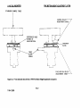
Two microspot stops. See Figure 7-6.
b.
Close the beam attenuator, and lower the sample table fully .
• These checks cannot be used with an instrument with both the 200mm diameter table and
the Microspot Optics, because the table cannot be moved out of the way of the optics to set
the arms at 90°.
( Section 2-7 continued on page 7-19 )
7-17
7109-C-229D