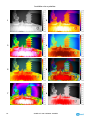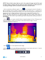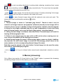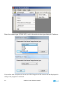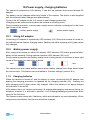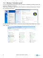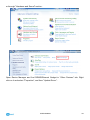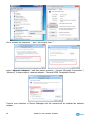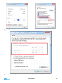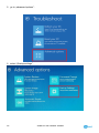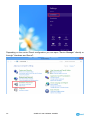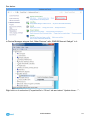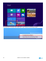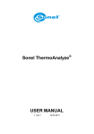
1
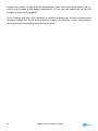
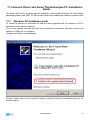
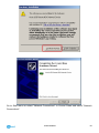
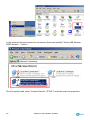
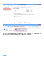
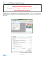
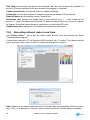
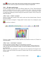
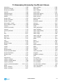
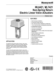
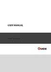
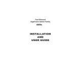
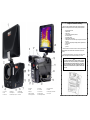
Testing and Calibration Laboratory SONEL S.A. Testing and Calibration Laboratory offers verification and calibration certificates for the following instruments used for measuring the electrical parameters: - insulation resistance meters, resistance meters, fault lop meters, meters of residual current device parameters, low resistance meters, Power Quality analyzers, Portable Appliance Testers (PATs) multifunctional meters with functional range covering the above-mentioned instruments, voltmeters, ammeters (analogue and digital), multimeters, digital ammeters, thermal imagers, luxmeters, pyrometers Calibration certificate is a document which confirms the conformity of the manufacturer declared parameters with the national standard, with determination of measurement uncertainty. According to the standard ISO 10012-1, Annex A, Sonel S.A recommends periodic application of metrological control for each instruments at least every 13 months. Note! In the case of instruments used for the tests related to protection against electric shock, the person performing the measurements should be absolutely sure that his/her instrument is in good working order. The measurements made with a malfunctioning meter can contribute to an incorrect assessment of protection of human health or even life. 10. microphone 15. SD card slot 20. laser pointer off button 11. Joystick 16. A, C, S buttons 21. Autofocus 1. Touch screen 4. LED flashlight 7. USB2.0 interface 12, stripe grip 17. Power-on button 22. battery charger / power indicator 2. IR lens 5. visual image lens 8. battery compartment 13, RS232 / TV interface 18, flashlight off button 23. touch pen slot 3. Laser Pointer 6. VGA video output / Joystick 9. View finder 14. Power supply interface 19, IR/visual image swith button QUICK START: Return to live view mode Switching between temperature ranges Freezing and storing image LED flashlight visual / IR image Laser pointer Auto focus Joystick: - up / down: manual focus - right / left: digital zoom SONEL S.A. ul. S. Wokulskiego 11 58-100 Świdnica tel. 74 85 83 878 fax 74 85 83 808 e-mail: [email protected] www.en.sonel.pl USER MANUAL THERMAL IMAGER KT-640 Attention! Every reference to "(number in brackets)", e.g. "(8)", used in this manual refers to the camera description presented on the back side of the front cover. USER MANUAL THERMAL IMAGER KT-640 SONEL S. A. ul. Wokulskiego 11 58-100 Świdnica version 1.0 29.08.2013 KT-640 Thermal Camera complies with current EU directives relating to electromagnetic compatibility and safety. Thank you for purchasing our thermal imager. KT-640 is a modern, easy and safe to use measuring device. Please acquaint yourself with the present manual in order to avoid measuring errors and prevent possible problems related to operation of the imager. All products of Sonel S.A. are manufactured in accordance with Quality Management System which is approved to ISO9001:2008 for the design, manufacturing and servicing. Due the continuous development of our products, we reserve the right to introduce changes and improvements in the thermal imaging camera and in the software described in this manual without prior notice. Copyrights © Sonel S.A., 2013. All rights reserved. This manual may not be copied, reproduced, translated or transferred to any electronic carriers or in machine-readable form, in whole or in part, without the prior written consent of Sonel S.A. 2 SONEL KT-640 THERMAL IMAGER TABLE OF CONTENTS 1. 1. SAFETY ................................................................................................................5 2. PREPARING THE CAMERA TO WORK. ..........................................................7 3. FUNCTION BUTTONS, JOYSTICK AND ON-SCREEN MENU......................7 3.1. 3.2. 3.3. 3.4. 4. BUTTONS LAYOUT...................................................................................................7 VIEWFINDER, TOUCH SCREEN, TV OUTPUT .............................................................8 ON-SCREEN INFORMATION ARRANGEMENT ..............................................................9 MENU. .................................................................................................................10 OPERATION INSTRUCTIONS AND THE CAMERA ADJUSTMENT .........10 4.1. TURNING THE CAMERA ON/OFF.............................................................................10 4.2. FOCUS ADJUSTMENT ............................................................................................11 4.3. ENLARGING IMAGE – ZOOM (X2, X4, X8) ...............................................................11 4.4. TEMPERATURE RANGE ..........................................................................................11 1.1.1. High temperatures filter...............................................................................11 4.5. EMISSIVITY...........................................................................................................12 4.6. LED FLASHLIGHT ................................................................................................12 4.7. MANUAL CALIBRATION .........................................................................................13 4.8. SELECTING THE COLOUR PALETTE ........................................................................13 4.9. LASER POINTER ....................................................................................................15 4.10. IMAGE MODES ......................................................................................................15 5. CAPTURING AND SAVING IMAGES WITH VOICE ANNOTATION.........16 6. MEMORY BROWSNIG........................................................................................18 7. THERMAL IMAGE ANALYSIS .........................................................................20 7.1. 7.2. 7.3. 7.4. 8. SPOT ANALYSIS. ...................................................................................................20 LINE ANALYSIS. ....................................................................................................21 AREA ANALYSIS. ...................................................................................................22 ISOTHERM ANALYSIS. ............................................................................................23 FUNCTIONS AND PARAMETERS SETTINGS................................................23 8.1. 8.2. 8.3. 8.4. 8.5. 8.6. 8.7. 8.8. THERMAL IMAGES ANALYSIS PARAMETERS. ............................................................23 TARGET PARAMETERS (OBJECT). ...........................................................................24 SYSTEM SETTINGS. ...............................................................................................25 FUNCTION SETTINGS. ...........................................................................................26 RESTORING TO DEFAULT SETTINGS. ......................................................................27 TOUCH PEN CALIBRATION ....................................................................................27 VIDEO RECORDING...............................................................................................28 WIFI ....................................................................................................................28 USER MANUAL 3 8.9. 8.10. 8.11. HELP .................................................................................................................. 31 INFORMATION ON HARDWARE AND FIRMWARE VERSION. ....................................... 31 FIRMWARE UPDATE ............................................................................................. 31 9. ACCURATE TEMPERATURE MEASUREMENT .......................................... 32 10. POWER SUPPLY, CHARGING BATTERIES .................................................. 33 10.1. USING AC ADAPTER. ........................................................................................... 33 10.2. BATTERY POWER SUPPLY...................................................................................... 33 1.1.2. Charging batteries ...................................................................................... 33 10.3. CHARGING BATTERY IN EXTERNAL BATTERY CHARGER. .......................................... 34 10.4. GENERAL RULES OF USING LITHIUM BATTERIES .................................................... 35 11. CAMERA'S DRIVER AND SONEL THERMOANALYSE PC INSTALLATION GUIDE............................................................................................... 37 11.1. 11.2. 11.3. 11.4. 12. WINDOWS XP INSTALLATION GUIDE ..................................................................... 37 WINDOWS 7 INSTALLATION GUIDE ........................................................................ 42 WINDOWS 8 INSTALLATION GUIDE ........................................................................ 48 SONEL THERMOANALYZE INSTALLATION GUIDE ................................................... 61 RECORDING INFRARED VIDEOS................................................................... 62 12.1. 12.2. 12.3. 12.4. 12.5. 12.6. RECORDING ON SD CARD. ................................................................................... 62 RECORDING ON HARD DRIVE. ............................................................................... 62 „SONEL THERMOANALYZE®” SETUP .................................................................... 63 RECORDING INFRARED VIDEO IN REAL TIME. ........................................................ 64 IR VIDEO MODE MENU ......................................................................................... 66 RECORD ANALYSIS DATA COMMAND .................................................................... 71 13. DATA TRANSMISSION ...................................................................................... 71 14. SPECIFICATIONS................................................................................................ 72 15. EXAMPLARY EMISSIVITY COEFFICIENT VALUES ................................. 75 16. CLEANING AND MAINTENANCE ................................................................... 76 17. CALIBRATION ..................................................................................................... 76 18. EQUIPMENT ......................................................................................................... 77 19. DISMANTLING AND DISPOSAL ...................................................................... 78 20. MANUFACTURER ............................................................................................... 78 1. 4 SONEL KT-640 THERMAL IMAGER 1. Safety Before you proceed to operate the camera, acquaint yourself thoroughly with the present manual and observe the safety regulations and specifications defined by the producer. Any application that differs from those specified in the present manual may result in a damage to the device and constitute a source of danger for the user. The camera must not be used in rooms where special conditions are present e.g. fire and explosion risk. It is forbidden to use damaged or malfunctioning camera and is partially or fully out of order. In case the camera is not used for a long time, its batteries should be removed. It is not allowed to use the camera with half-closed or opened battery cover and do not use any other power adapter than the one supplied with the camera. Repairs may be carried out only by an authorised service point. KT-640 Thermal Imager is designed to measure and record the images in the infrared. The camera is constructed in a manner which gives you maximum performance and safety at work, however the following precautions must be adhered to at all times (in addition to any advised precautions applicable at the relevant work-site or work area): Keep the camera steady during operation. Do not use the camera in ambient temperatures exceeding its operation and storage temperature ranges. Do not direct the camera toward very high intensity radiation sources such as the sun, lasers or welding arcs etc. Do not expose the camera to dust and moisture. When operating the device near water, ensure that it is adequately guarded against splashes When the camera is not in use or is to be transported, ensure that the unit and its accessories are stored in the protective carry case. Do not jam the loudspeaker holes on the camera body. Do not re-switch on the imager before 30 seconds after switching it off and do not remove the battery while operating the instrument. Do not throw, knock or shake intensely the camera and its components in order to avoid the damage. Do not attempt to open the imager body, as this action will void the warranty. Keep the SD memory card for the exclusive use of the camera. During operation, if the camera is to be moved from hot/cold place to cold/hot place, e.g. from inside/outside to outside/inside of a room, switch the imager off and leave it in the new workplace for 20 minutes, then turn it on and start normal operation with an accurate temperature measurement. Sudden and rapid changes in ambient temperature may cause fault temperature measurement and even damage camera’s IR detector. USER MANUAL 5 FPA setting (FPA -. Focal Plane Array): in order to ensure accurate temperature measurement, the FPA detector was calibrated in different temperature points. After switching the imager on, it performs auto calibration procedure (3 times during the first minute). During the calibration, for about 2 seconde, the device does not respond to user’s activity ( it is indicated by „calibration” word on screen). Apart from that, autocalibration, of 2 seconds duration, performs automaticly during operation of the device, and is dependent on external conditions and i salso indicated by „calibration” word displayed on screen. Calibration can be performed manually at any time. In order to do that you need to go to real time mode screen by pressing C button (6) as many times until there is only infrared image being displayed on screen with central point selected. Then you need to press and hold C button for 2 seconds – calibration procedure will be performed, and it will be indicated by „calibration” note on screen. During imager operation its housing temperature increases and it’s a normal phenomenon. NOTE! KT-160 Thermal camera has no parts that could be repaired by its user. Never attempt to dismantle or modify the camera. Opening the unit invalidates the warranty. NOTE! Laser pointer installed in the camera may be dangerous to eyes, in case of direct contact! DO NOT DIRECTED THE LASER BEAM TOWARDS OTHER PERSONS OR ANIMALS! Please note that the laser beam may reflect off shiny surfaces. After turning the camera on, it performs internal test, during which, for few seconds, laser pointer is being turned on as well. After turning the camera on, until it reaches the point of being fully operational it is forbidden to aim it at human and animals!! NOTE! Use only standard and additional accessories, listed in "Equipment" section. Using other accessories does not ensure proper operation of the camera and may cause its damage. 6 SONEL KT-640 THERMAL IMAGER NOTE! Due to the continuous development of the device, the design of the display and its certain features may be slightly different than presented in this manual. 2. Preparing the camera to work. KT-640 can work with touch screen detached, however having it mounted significantly simplifies its operation and features selection. When touch screen is detached, main menu functions and analysis tools can be activated by pressing and moving Joystick. Thermal image can be viewed through view finder (9). It is possible to activate laser pointer, flashlight, real time image preview (buttons 18-20), using auto focus (button 21), manual focus adjustment and zooming the image with Joystick (11). In order to have both thermal and real time image projected on large screen (1) and to have easy access to advanced functions, attach it by the grip to the socket on the upper side of the camera. The grip should be slided into the socket from the front side till the end in the manner that allows the proper connection of the LCD contact pins(25), and then secure the grip using tightening gear (24 - by turning it right). Touch pen slot (23) is located on the bottom part of the screen frame (1). Touch pen is designed to work with the touch screen. 3. Function buttons, Joystick and on-screen menu 3.1. Buttons layout Access to the camera's functions is provided through the buttons (16) located on the top side of the housing ( , , ), buttons (18..21) located under the power off button and through Joystick (11). Buttons layouts is presented at the inside cover page. USER MANUAL 7 - button allowing to switch between temperature ranges displayed on screen and from auto mode to manual mode. - press this button to cancell currently selected function. Pressing C button several times will result in returning to the previous sub menu (stepping back from different levels of parameters and subfunction menus) until getting only visual image available on screen, with no menus on. Press and hold button for 2 seconds, while having only thermal image on screen, to perform calibration of the camera. - freezes thermal image on screen. Press the button again to save the image into the memory. Joystick can be pressed like button and it can also be moved in both up-down and leftright axis. Joystick operation depends on the currently running function. 3.2. Viewfinder, touch screen, TV output During the camera operation in real time mode infrared image is displayed on both screen (1) and viewfinder (thermal image refresh rate is 60 times per second). After selecting proper functions by using buttons or touch screen, the following are being displayed on screen: drop down menu bar, expanded analysis toolbar (its on-screen location can be changed), status bar, temperature range bar and its corresponding color palette, and central point with its temperature value: Additionally, above the bottom bar messages of each functions are being displayed (e.g. "saving", "SD card removed"). Touch screen menu elements and temperature range bar hide after pressing They show up again after freezing image on screen or after touching the screen. 8 SONEL KT-640 THERMAL IMAGER button. Output signal from the camera can be simultaneously viewed at the same time on a TV screen (monitor) by using RS232/Video cable (socket (13) on the camera) in PAL or NTSC (depends on the video output settings selected in System Settings menu [section 8.3] ). 3.3. On-screen information arrangement Bottom bar contains: real time clock; current mode status (real time image, frozen image or memory browsing); zoom ratio; battery and power supply indicator; no SD card information (visible only when SD card is missing). USER MANUAL 9 An additional point indicating the location of the lowest or the highest temperature can be put onto the screen. Activation and selection of this point can be made in the analysis parameters settings. (section 8.1). Functions put together in 4 groups can be selected upon expanding upper drop down Menu. Analysis Tools options depend on whether the camera displays stored image, frozen image or real time image. 3.4. Menu. In real-time mode, when there is no icons on the screen, press the Joystick twice or touch the touch screen once, and then repeat the same on the appearing icon to make the drop down menu expand. It contains a list of functions, their settings and parameters. Menu functions are grouped into 4 sections. Navigating through the Menu is executed by using the Joystick or by the touch secreen.: Individual functions available on the menu are described in subsequent sections of this manual. 4. Operation Instructions And The Camera Adjustment 4.1. Turning the camera on/off Press and hold the (7) button for around 2 seconds to turn the camera on. Splash screen will apear on the display and then the camera will perform self-check test, after which the camera is ready to use and goes into displaying real time infrared image. In order to turn the camera off press and hold the "Power" button until the screen turns off. 10 SONEL KT-640 THERMAL IMAGER 4.2. Focus adjustment Focus can be adjusted in manual or in auto mode. In manual mode aim the lens at the target and then move the joystick up or down to zoom the focus point in or out. For very precise focus setting it is recommended to use the "Zoom" function. To adjust the focus automatically, use the (21) button. Press it and the camera will focus, provided that the object, which the camera is being set to focus on, has a large thermal contrast. In case the auto focus results are dissatisfying, use the manual focus mode. 4.3. Enlarging image – Zoom (x2, x4, x8) Moving the Joystick right allows to magnify thermal image 2-, 4-, up to 8 times bigger, while moving the Joystick left makes the image zoom out down to its nominal size. Zooming can be also performed by pressing the field with the magnification symbol and its ratio on it. It is located on the bottom bar on the screen (see section 3.3). Image magnification allows accurate focusing. It should be remembered that KT-640 supports digital zoom only, so it is not advisable to save IR thermal images digitally enlarged.. 4.4. Temperature range Temperature range can be adjusted by buttons or by the use of touch screen when the camera is in the real time mode, and when a real time infrared image is being displayed on screen. Press (6) button or click on icon or on the temperature value on icon on the touch screen, to switch from automatic temperature mode into manual mode. This transition will be indicated by the "M" letter replacing "A" letter on the screen (see section 3.3) and the temperature, that can now be adjusted manually, will be highlighted by the blue line framing the field in which it is located. Now you can change the upper limit of the temperature range by moving Joystick up/down or by sliding touch pen across the temperature bar. Whili changing the temperature, its value is marked by yellow background. To change the lower range press (6) button again. Press and hold (6) button for 2 seconds, or click "M" letter on to go back into automatic temperature range selection mode. icon with touch pen, 1.1.1. High temperatures filter. Full temperature range of KT-640 is -20°C do +800°C. It is divided into two filter ranges: standard (filter 1 range: -20°C do +250°C) and high (filter 2 range: +200°C do +800°C). When the temperature of the measured object exceeds selected filter range, instead of temperature values, the camera will display following symbols on screen: "+++" or "---". Those symbols indicate manual filter range adjustment. To change the filter range go to real time image and press USER MANUAL button for 3 seconds. 11 4.5. Emissivity. To change the emmissivity coefficient value press and hold the value above icon with touch pen (on ε sign), and while keeping the pen pressed against the touch screen, move it up (value will increase) or down (decrease). ε value can be also changed in "Target" menu in target parameters settings (described in section 8.2): Whilst clicking on emissivity coefficient symbol (ε) on , icon, or after selecting this function from main menu: the list of the most common materials with their emissivity coefficient values will be displayed.: The right material can be selected by navigating across the list with Joystick and confirmed by pressing the Joystick button. Close the list by pressing ( also be made by using the touch pen. . )button. Selection can 4.6. LED flashlight In order to improve the work in dark locations KT-640 has been equipped with LED flash12 SONEL KT-640 THERMAL IMAGER light. Turning it on is executed by pressing (18) button. Pressing the (18) button again will increase the intensity of the flashlight brightness (3 levels) up to its maximum level. Pressing the (18) button further will repeat the sequence (turned off - level 1 - level 2 - level 3 turned off - ...etc.) Information about the flashlight status and its current brightness level is displayed as an icon in the low right corner of the screen. Enabling the flashlight and changing its brightness can also be executed by clicking its icon on touch screen with pen. This function is available when activated in the system settings menu (see section 8.3). 4.7. Manual calibration During operation, the camera runs periodic auto-calibration procedure (it is signalled by the closing shutter sound and the "Calibration" word appearing on the bottom of the screen). Calibration can also be triggered manually at any time. while being in real time mode (with infrared thermal image being displayed), press and hold onds.. button for 2 sec- 4.8. Selecting the colour palette Color palette corresponding to the temperature values can be changed in every mode. Select palette option in the Menu.: or click on the temperature bar on screen and a window with the selection of 8 palettes will pop up on. Palette selection is made by clicking on chosen palette bar. After selecting desired palette click once again on the temperature bar or press fault. USER MANUAL button (6). Palette no.2 is set by de- 13 Available colour palettes: 1 2 3 4 5 6 7 8 14 SONEL KT-640 THERMAL IMAGER 4.9. Laser pointer Laser pointer can be activated, while being in real time mode, by pressing (20) button. After activating or deactivating laser pointer, corresponding information is being displayed on screen for 3 seconds. NOTE! Laser beam may damage eyes in case of direct contact! DO NOT LOOK INTO THE LASER BEAM DIRECTLY AND DO NOT DIRECTED THE LASER BEAM TOWARDS OTHER PERSONS OR ANIMALS! Special caution should be excercised as the laser beam may reflect off shiny surfaces. Due to safety reasons, Laser pointer is available after enabling it in function settings menu (see "function settings", section 8.4). 4.10. Image modes KT-640 captures both thermal and visual images. Thermal image mode can be switched into visual image mode at any time while being in real time mode, or by freezing thermal image on screen ( button), and also during browsing thermal images stored in the memory. Press (19) button to swith into visual image mode. Press the same button again to return to thermal image mode. Displayed image mode can also be changed using touch screen. In order to do that expand analysis tool bar and selec proper button on touch screen (depending on whether the image is in real time mode or it's frozen one). Description of analysis tool is located in section 7. In case of frozen image or browsing thermal images stored in the memory, pressing button will switch to visual image. Press to return to thermal image mode. In real time image mode, press button to put thermal image on top of the visual one, with possibility to adjust transparency (FUSION mode): USER MANUAL 15 Infrared image transparency level and distance from the object can be adjusted using vertical and horizontal sliders (using touch screen or Joystick). Selecting the lowest transparency value will result in only visual image being displayed. Pressing "IR" (or button) results in return to displaying full screen infrared image in real time mode. It is advised to use FUSION mode for distances greater than 1,5m; In case of smaller distances significant displacement of both images can be observed (Parallax phenomenon). 5. Capturing and saving images with voice annotation Caution. KT-640 utilizes external memory - SD card put inside the slot (15). If the SD card is not inserted the camera will display infrared images in real time mode, and image can also be freezed or being analysed, however it is not possible to store it in the memory. The lack of SD card is indicated by the symbol displayed on status bar: KT-640 displays image continuously, refreshing it 60 times per second. To capture an image, press (6) button, which will freeze an image and will display menu elements on screen. Information about the "freeze" mode is displayed on the bottom bar. At this point: - press button to save thermal image along with its corresponding visual image; - click on temperature range icon (number defining upper range limit), or click on icon (number defining lower range limit) to switch into manual adjustment of upper and lower temperature range limits (see section 4.4). This operation allows to choose the most optimal temperature ranges right after freezing an image on screen. 16 SONEL KT-640 THERMAL IMAGER NOTE! Chosen limits values that are set for the captured images and will be used for those images, but they will also remain set after returning to real time mode. After saving an image switch to automatic temperature selection mode. - click on emissivity coefficient symbol „ε” on icon to change its value for infrared image by selecting it from the table of materials. Click on the value next to „ε” symbol to define its exact value by pressing touch pen on the value and moving pen up and down (instruction on how to change emissivity coefficient values is described in section 4.5 ). NOTE! The value selected for the captured image will also remain active after returning to real time mode. If you want to go back to the previous value you must select it again. - click on icon or press Joystick button to expand analysis tool bar. Clicking on individual icon allows to perform the analysis of the whole thermal image or its part (detailed description in section 7); - click on icon to view captured visual image; - click on icon to open dialog box that allows to record voice note (up to 1 minute lenght), which will be saved along with thermal image: USER MANUAL 17 press to start recording (backward counting starts showing remaining time), press to stop recording, and press to play recorded note. The record can be repeated, and doing this will erase the previous one; - press to mark image. On the file list (see section 6 "memory browsing") the image will be marked with the flag icon placed in the upper left corner; - press to save thermal image along with the optional voice note and mark. The same result can be achieved by pressing , button. Remarks: 1. Thermal image is saved in "extended jpeg format". Thanks to that it can be viewed in all image browsers and graphics softwares (stored preview image will be viewed in those cases). In addition to that all information related to the thermogram is stored in one single extended jpeg file as well: temperature of each and every pixel of thermal image, voice note and mark (flag symbol - described above). 2. editing thermal image in software other than Sonel ThermoAnalyse will result in loosing all thermographic data. 3. If there is not enough space to save a file on SD card or when a saving error occurs, proper information will be displayed on screen. 4. Saved thermal image file name is IRIxxxxx.jpg (where xxxxx are digits). Additionally separate file with visual image is saved (as VISxxxxx.jpg, where xxxxx is the same number as in its corresponding thermal image file name). Both files must be placed in the same folder if visual image is to be used for analysis in Sonel ThermoAnalyse program. - click on 11). icon to go to infrared video record mode (described in details in section 6. Memory browsnig. Go to Menu (see section 3.4) and click on the "Filelist" option to proceed into browsing and editing images stored in the memory (on SD card). 18 SONEL KT-640 THERMAL IMAGER Click on the thermal image thumbnail to open it in the mode allowing to view its corresponding visual image, play voice note and perform analysis (click analysis submenu). Switch to infrared video file list to open videos stored on the memory card. icon to open Click on the symbols located on the bottom bar to: - go to the list of saved static thermal images; - go to the list of saved infrared video files; and - to toggle between screens with saved files (between those two symbols number of screens available is shown along with the number of currently viewed screen); - delete selected thermal image; - delete all thermal images; - return to real time mode. Return to real time mode can also be executed by pressing USER MANUAL (6) button. 19 7. Thermal image analysis Thermal image analysis is possible for every image mode - real time, freezed and images stored in memory. Activate expanding AnalysisTools bar from main Menu:: or by pressing low to perform: . icon. After expanding AnalysisTools bar following icons selection al- - spot analysis (see below); - line analysis (see below); - area analysis (see below); - isotherm analysis (see below); - deleting of active area (object) of analysis. Remaining icons, available on the bar depending on the image mode we're in, execute the functions described in previous sections. Press the triangle on the bottom of the bar to turn the bar back into icon. 7.1. Spot Analysis. Press pen (or use Joystick) on button, available under expandable AnalysisTools icon, to add spot on screen. The spot can be moved at any place on the screen with touch pen. Up to 8 spots can be added on screen. Each point is accompanied by its temperature indication located in small field next to it. 20 SONEL KT-640 THERMAL IMAGER To delete spot press it with touch pen (select it) and click symbol on tool bar. 7.2. Line Analysis. Press pen (or use Joystick) on button, available under expandable AnalysisTools icon, to add line on screen. Added line is displayed on screen with one end marked by yellow square and the other end with temperature indication in rectangle-shaped box. Depending on the options selected in "analysis settings" (see section 8.1), it can display maximum, average or maximum temperature on the line. When the maximum temperature is selected in "analysis settings", displayed temperature value for given line is red coloured. For average temperature it's black, and for minimum it's blue. USER MANUAL 21 Using touch pen line can be moved to any place on the screen. Press and hold the square with temperature and slide it to a new place on screen. Press the touch pen against the square on the other end of line, and move its position (to prolong the line, rotate it, etc.). To delete line select it by pressing square or rectangle with touch pen (green arrow will appear when selecting square) and press bin symbol on tool bar. Up to 8 lines, which temperatures are read and displayed in rectangle boxes at their end, can be added on screen. 7.3. Area Analysis. Press pen (or use Joystick) on button, available under expandable AnalysisTools icon, to add rectangle area with its temperature on screen. Depending on the options selected in "analysis settings" (see section 8.1), it can display maximum, average or maximum temperature within the area. When the maximum or maximum temperature is selected in "analysis settings", displayed temperature value is accompanied by its corresponding spot within its area. When the maximum temperature is selected in "analysis settings", displayed temperature value for given area is red coloured. For average temperature it's black, and for minimum it's blue. Using touch pen area can be moved to any place on the screen. Press and hold any point within the area and slide it to a new place on screen. To enlarge the area or to change its shape press touch pen against the corner of the area, and, while keeping it pressed, move it and change the areas' shape as per your convenience. Up to 8 areas can be added on screen. 22 SONEL KT-640 THERMAL IMAGER To delete the area select it by pressing pen within the area. Green aarows will appear in all corners. Then use bin symbol located on tool bar. 7.4. Isotherm analysis. Press pen (or use Joystick) on button, available under expandable AnalysisTools icon, to initiate isotherm analysis mode. This mode is available only for images in real time mode and for frozen images. Slide markers on temperature bar to set the temperature range, for which isotherm area will be marked with black, white or green colour (depends on analysis settings - see section 8.1). Isotherm temperature range is displayed on the screen at the bottom bar. Press button to return to regular infrared image mode. 8. Functions and parameters settings. Functions and parameters settings can be adjusted in part 2 and 3 of main Menu: 8.1. Thermal images analysis parameters. After selecting main Menu, go to section 2 and select (with touch pen or Joystick) „Analysis” tab: USER MANUAL 23 Below window will open: Using Analysis Setting window following parameters can be adjusted: Isotherm Color – this is the color that is being applied to the areas from selected temperature range during isotherm analysis; Hot/Cold Spot – you can decide here whether or not an additional spot showing coldest and hottest point along with its temperature value, should be visible on screen, as an addition to central point. Enabling this function will result in showing the lowest or the highest temperature on screen, depending on the selected temperature alarm (see "TempAlarm"); AnalysisFunction – Select the temperature that will be displayed during line or area analysis (average, maximum or minimum); TempAlarm – Audible alarm that will activate after exceeding selected temperature level. Selecting "Low" will trigger the alarm when the temperature drops below selected "AlarmValue". Selecting "High" will trigger the alarm when the temperature exceeds selected "AlarmValue"; AlarmValue – Select temperature value, exceeding which will trigger audible alarm. This field is active when "TempAlarm" is set to "High" or "Low". 8.2. Target parameters (object). After selecting main Menu, go to section 2 and select (with touch pen or Joystick) „Target” tab”: In the dialog box that opens you can set following parameters: 24 SONEL KT-640 THERMAL IMAGER Emiss – value of emissivity coefficient of the measured object (table with emissivity coefficient values for different materials is available in section 14); Relhum – Relative humidity; Distance – object’s distance from the camera (this value is not related with image focuse, but it allows to correct the influence of the medium in which the radiation propagates (dust, mist, smoke, vapor) on the accuracy of the measurements; BackgroundTemp – background temperature (background surrounding the object, not the place where the mesurement is made) - allows you to set the proper relation between ambient temperature and the measured objects and it allows to adjust the temperature reading; This feature is useful when measurements are performed from certain distance, for example, in a location where the ambient temperature is different than the one surrounding measured object. In most cases there is no need for adjusting this value; Tamb – real ambient temperature measured near the converter (value measured by sensor); DewPoint – Dew point value for the location (place) measured by the camera's sensors. 8.3. System Settings. After selecting main Menu, go to section 2 and select (with touch pen or Joystick) „System” tab: In the dialog box following settings can be done: USER MANUAL 25 TempUnit – temperature unit selection (°C or °F); FrameAver – frames averaging - parameter that specifies the number of frames used to freeze and store an image. in case the nuber is increased above 1, the camera, during the process of capturing (freezing) thermal image, uses special denoising algorithm where the image is averaged from a larger number of captured frames (2, 4, 8 or 16). in case of selecting the parameter's value above 1 it is advised to use tripod, as all vibrations causing even the slightest movement of the camera result in degrading the sharpness of the image (blurred images); Language – language selection (Polish, English, Chinese); VideoOut – PAL, NTSC or off; Date(Y/M/D) – date setting (year/month/day); Time(H/M/S) – time setting (hours/minutes/seconds). 8.4. Function Settings. After selecting main Menu, go to section 2 and select (with touch pen or Joystick) „Function” tab: In the dialog box below following settings can be done: 26 SONEL KT-640 THERMAL IMAGER Lens – lens selection (only when the camera is calibrated to work with more than one lens); Laser – Enabling/Disabling the possibility of using laser pointer; FlashLight – Enabling/Disabling the possibility of using LED flashlight; AutoPowerOff – disable or enable to power off after 10, 30 or 60 minuts of no activity; PowerAlarm – disable or enable audible alarm when battery level is critically low (10 times every minute). 8.5. Restoring to default settings. After selecting main Menu, go to section 2 and select (with touch pen or Joystick) „Default” tab: And then confirm the action in the window below: Default settings: laser pointer, LED flashlight, Auto Power Off, Power alarm and temperature alarm – disabled; Frame Aver = 1 (disabled frames averaging). 8.6. Touch Pen calibration After selecting main Menu, go to section 2 and select (with touch pen or Joystick) „TouchPen” tab: After selecting this option, four markers (points) will start appearing in the corners of the screen ,one by one starting from the top left corner, proceeding in the clockwise direction. Fift one will appear in the center of the screen. User should always be pressing the center of each marker with touch pen: USER MANUAL 27 Then confirm the end of calibration procedure. NOTE! If the calibration procedure was not conducted properly and its results were accidentally saved, and the touch screen does not respond to the stylus touch, use Joystick to repeat the calibration procedure.. 8.7. Video recording infrared video recording procedure has been described in details in section 11.1 8.8. WiFi This function allows to set the camera to work wirelessly. Network, to which the camera will be connected can not be password protected.. NOTE! PC-camera communication is possible after installing proper drivers. (section 12). To get wireless connection select "WiFi" option from the Menu: WiFi Setting window will open. Use stylus and turn the wireless network on as on the image below: 28 SONEL KT-640 THERMAL IMAGER After a while all the networks found will be displayed in the window: Select the line, containing desired network, with a stylus and additional window with IP address will appear: The IP address should be used in Sonel ThermoAnalyse software. Go to File -> Video -> Device Video...: USER MANUAL 29 Select the camera type (KT640-WIFI), and in the window below type obtained IP address: Connection with computer will be set, and the image from the camera will be displayed directly in the program in real time. 30 SONEL KT-640 THERMAL IMAGER Detailed description on how to use infrared video recording options is available in section 11 "Infrared Video Recording" and also in Sonel ThermoAnalyse user manual. 8.9. Help Select "help" option to activate short guide containing basic information on how to use the camera, displayed on the screen. 8.10. Information on hardware and firmware version. "Info" option displays information on the hardware and the firmware version used in the camera on the bar at the top of the screen. 8.11. Firmware update To update the firmware upload the latest version of it into the main folder on SD card and insert the card into the slot (15). Then choose option as below: Update will be performed automatically if there is a proprer version of the firmware uploaded on SD card (newer version than the one currently used). USER MANUAL 31 9. Accurate temperature measurement The accuracy of temperature measurement depends mainly on the following factors. During measurement, the camera makes corrections based on signals from its sensors. However, in certain situations, manual correction of parameters might be necessary. Emissivity. Infrared radiation measurements are based on reception of infrared radiation emitted by objects. The amount of radiated energy depends on two base factors: the temperature and the emissivity of the surface of an object. Default value of the emissivity coefficient is 0.98 and it is applicable to most surfaces. Values of the emissivity coefficient for some materials are presented in the emissivity table (see chapter 14). Improper value of the emissivity coefficient can cause significant errors of the temperature readout, therefore the camera allows for adjustment of the emissivity coefficient value within the range of 0.01...1.00 (see section 4.5 and 8.2). When changing the emissivity coefficient value, it is crucial to check the readout of ambient temperature in the camera (see below). Accuracy of measurement also depends on ambient temperature. By default, the temperature measured by the camera is used, however it might be improper, especially during operation in low temperature or measurements from a location of temperature differing from ambient temperature of the examined object. In order to maintain accuracy of measurements, proper value of ambient temperature should be accounted for - especially, if the emissivity coefficient is changed or these changes will be performed by processing a thermal image with computer program. This value should be changed manually in order to determine proper relation of the examined object temperature and the temperature of certain types of surroundings (e.g. the sky, snow). Adjustment of ambient temperature is described in section 8.2. The influence of distance from the examined object onto the accuracy of measurement can be significant, depending on the medium the object is placed in (air, for, smoke, etc.) and its reducing properties related to thermal radiation. It is possible to correct the default value (1.8 m) within the range of 0.1...30 m. The method of adjustment is described in section 8.2. Relative humidity can also influence the accuracy of measurement; the default value (70%) can be changed to any value within the range of 0...100% (this function is described in section 8.2). Additionally, to achieve an accurate temperature readout, hold the camera stably and adjust focus properly. Before capturing the image, it is recommended to invoke the auto-calibration of the camera (by pressing and holding 32 button for 3 seconds – see section 3.1). SONEL KT-640 THERMAL IMAGER 10. Power supply, charging batteries The camera is powered by LiOn battery. It can also be powered from mains through AC adapter. The battery can be charged while being inside of the camera. The device is also supplied with the external battery charger and spare battery. Connect the AC adapter to the (14) socket to start charging procedure. Charging can be performed only when the camera is not being used. During camera operation, current power supply source indicator is displayed in the lower right corner of the screen.: - battery power supply - mains power supply 10.1. Using AC adapter. Connecting AC adapter is signalled by LED indicator (22). When the camera is turned on, the indicator shows battery charging status, flashing red while charging and lit green when fully charged. 10.2. Battery power supply. After turning the camera on withot AC adapter, LED indicator (22) flasher green/red alternately for few seconds. During camera operation LED indicator (22) is off. During camera operation the battery charge level is being shown in real time in lower right corner of the screen on status bar as below: max. min. The camera can also make audible sound when battery charge level drops down below the critical value. This feature can be enabled in "function settings" (section 8.4). 1.1.2. Charging batteries When the camera is turned off, and the battery is inside, connecting the AC adapter and starting the charging procedure is signalled by the charging indicator (22) - flashing red while charging and lit green when fully charged. When the battery is not being charged the indication is turned off. LiOn battery does not require performing full charging/discharging sequences during exploitation, however it is advised to perform 3 full charging/discharging procedures when using for the first time. The camera comes along with 2 batteries, which are advised to be used alternately. When using the second battery, the first one should be charged. USER MANUAL 33 NOTE! Use only the battery, AC adapter and external battery charger supplied along with the camera. NOTE! Do not remove the battery from the camera while it’s being charged. NOTE! Battery charging should be performed in 0...40°C temperature range. 10.3. Charging battery in external battery charger. NOTE! Switch the camera off before removing the battery. To remove the battery from the camera, pull the battery comprtment cover's (8) prong (26) and open the battery compartment cover: Push the battery lock lever (27) above the battery and the battery will partially slide out of the compartment, allowing to remove it. After inserting the battery into charger and after connecting power supply, the charger will make audible sound and will display "**Hr**Min" on screen to inform about the battery charge status. After finishing the charging procedure charger will also make audible sound and will display "FULL" on screen to inform about the battery being completely charged. 34 SONEL KT-640 THERMAL IMAGER 10.4. General rules of using Lithium batteries If the device is unused for an extended period, remove the battery and store it separately. The battery should be stored in dry, cool and well-ventilated place and it should be protected from exposure to direct sunlight. Optimal ambient temperature for long time storage of the battery should be maintained below 30 Celcius degrees. If the battery is stored for an extended period at a location with high temperature in it, then the chemical processes occuring within it may shorten its expected life span. Typical estimated life of Lithium-Ion battery is about 500-1000 charge cycles. Those batteries reach their maximum capacity after being formatted (2-3 charge/recharge cycles). The most important factor that influence the life of the battery is the discharge level (discharge depth). The more discharged is the battery, the shorter is its life span. During normal operation camera works until reaching certain point of discharge. Reaching this point is when the charging should be performed (in the camera or in external charger). Memory effect occurs in Ion batteries in limited way. Those batteries can be charged even when not reaching discharge level, with no serious consequences. It is important however to perform full charging cycle once in a while during regular operation of the camera. LiOn batteries continue to discharge at approximately 30% a month while in storage. Keeping the batteries in high temperatures may even speed up this process twice. In order not to allow extensive discharge ot the battery, after which formatting is necessary, charge the battery once in a while (including the ones that are not being used). Modern, fast chargers detect both too low and too high battery temperatures and react appropriate. Too low temperature should prevent from starting the charging procedure, which could irreversably destroy the battery. increase of the battery temperature suggest that charging procedure is over and this is normal and expected phenomenon. However USER MANUAL 35 charginf the battery in high ambient temperature, apart from decreasing battery life, results in the increase of the battery temperature. In this case the battery will not be fully charged to reach its full capacity. Do not charge and use LoOn batteries in extreme temperatures. Extreme temperatures decrease battery life. Avoid placing devices running on batteries in very warm places. Nominal working temperature must be strictly abide. 36 SONEL KT-640 THERMAL IMAGER 11. Camera's Driver and Sonel ThermoAnalyse PC Installation Guide. The driver and the PC program can be installed on Microsoft® Windows (XP and higher) operating system (x86, x64). KT-640 driver installs as an additional network interface card. 11.1. Windows XP installation guide To install the camera on Windows XP use the driver supplied with the camera on CD or download it from www.en.sonel.pl. Turn on the camera and wait antil self test procedure is completed, and then connect the camera to USB port on computer. Computer will detect new hardware: Choose "install from a list or specific location" and then select to search the driver is selected location:: USER MANUAL 37 Driver installation will begin: Information suggesting that the driver is not compatible with our operating system. Ignore it and press "Continue anyway": 38 SONEL KT-640 THERMAL IMAGER Go to Start menu or select "Network Connections" in Control Palen and select "Network Connections": USER MANUAL 39 In the window that opens select the connection that uses installed "Acme USB Remote NDIS Network..." device: Go to Properties and select "Internet Protocol (TCP/IP)" and then select its properties: 40 SONEL KT-640 THERMAL IMAGER click on "Use the following IP address" and type in IP address (see below): Click OK and the camera is ready to work with Windows XP operating system. USER MANUAL 41 11.2. Windows 7 installation guide Turn on the camera and wait antil self test procedure is completed, and then connect the camera to USB port on computer. Open "Device Manager" (right click on My Computer on desktop and choose its "Properties" from drop down menu): or open it through Control Panel, to which you can get access ,depending on the configuration, directly: 42 SONEL KT-640 THERMAL IMAGER or through "Hardware and Sound" section: Open Device Manager and find RDNIS/Ethernet Gadget in "Other Devices" tab. Right click on it and select "Properties", and then "Update Driver": USER MANUAL 43 Go to „browse my computer...” and „let me pick from...”: select „Network Adapters”, and then select producer – choose „Microsoft Corporation” ( „Microsoft” in some cases); network adapter – Remote NDIS Compatible Device: Confirm your selection in Device Manager and the camera will be installed as network adapter: 44 SONEL KT-640 THERMAL IMAGER Go to Open Network and Sharing Center in Sontrol Panel or through shortcut on task bar: Go to „change adapter settings”: USER MANUAL 45 Select connection using „USB Ethernet/RDNIS Gadget”: Right click and select „Properties”, chose Internet Protocol Version 4 and click on its Properties as below: 46 SONEL KT-640 THERMAL IMAGER Type in IP address as below: Press ok and data from the camera can be transferred to computer. USER MANUAL 47 11.3. Windows 8 installation guide Before installing on Windowds 8 it is required to switch it into mode allowing installation of anouthorised drivers: 1. Move mouse cursor to lower right corner of screen and select "Settings"”: 2. Click on „change PC settings”: 48 SONEL KT-640 THERMAL IMAGER 3. in the next window select "General" and then "Restart now”: 4. go to „Troubleshoot”: USER MANUAL 49 5. go to „advanced options”: 6. select „Startup settings”: 50 SONEL KT-640 THERMAL IMAGER 7. select „Restart”: 8. In the next window press F7 on keyboard and the system will reboot in the mode allowing unauthorized drivers installation. Proper driver installation: - Turn on the camera and wait antil self test procedure is completed, - connect the camera to computer USB port, - go to „Settings”: Go to Control Panel: USER MANUAL 51 Depending on the control Panel configuration you can open "Device Manager" directly or through "Hardware and Sound": 52 SONEL KT-640 THERMAL IMAGER See below: In Device Manager wingow find „Other Devices” with „RNDIS/Ethernet Gadget” in it: Right click on it and select „PropertiesGo to “Driver” tab and select “Update driver…””: USER MANUAL 53 And select an option as below: 54 SONEL KT-640 THERMAL IMAGER Choose „let me pick…” option as below: And then select producer – „Microsoft”, Adapter – „Remote NDIS compatible Device”: USER MANUAL 55 Ignore the wwarning and click Yes to confirm: Proper installation will be confirmed as below: 56 SONEL KT-640 THERMAL IMAGER In device manager another network adapter will appear – „USB Ethernet/RNDIS Gadget”: After finishing installation go to Desktop: USER MANUAL 57 Go to the bar in low right corner and select "open Network and Sharing Center": 58 SONEL KT-640 THERMAL IMAGER Select „Change adapter settings”: Chose network connection linked to „USB Ethernet/RNDIS Gadget”: Right click on selected network connection and select "Properties". In "Networking" tab find and select "Internet Protocol Verision 4"and go to its Properties. USER MANUAL 59 Go to „Use following IP address and type fil lit in as below: Click OK to accept changes and the connection will be configured properly. 60 SONEL KT-640 THERMAL IMAGER 11.4. Sonel ThermoAnalyze Installation Guide Installation procedure is identical on all computers regardless of the operating system. It is recommended to close down all applications before installing the program. After inserting the CD containing the software (supplied with your camera) into CD-ROM drive, installation dialog box will appear. If the installation box doesn’t appear automatically, double-click “autorun.exe” file in the CD’s main folder. After selecting language new dialog box will appear. Choose “thermal cameras” and then “install ThermoAnalyze”: Installation process will begin, follow the on-screen instructions. NOTE 1: Without changing the default installation directory, the installation procedure will allow the program to be installed in C: \Program files\ Sonel ThermoAnalyze. The installation procedure will add a shortcut icon Launch Sonel ThermoAnalyze to the Desktop and to the Start menu. NOTE 2: When starting the program for the first time, with the camera connected in online mode, Windows Firewall alert may appear on screen. If this case, click allow to connect to private networks. USER MANUAL 61 12. Recording infrared videos IR video can be recorded and stored on both SD card, and also directly on PC hard drive, using Sonel Thermo Analyze program supplied with the camera. Whether recording on SD card, or directly on PC's hard drive, all information is being stored - each frame is thermogram, meaning that the temperatures of each point are stored independently (just like for the static images). 3 files with the same names and different extensiones are stored: video file (.avi) in h.264 format, which can be played in any video player installed on PC; second one is .raw file containing thermogram data. The third one is .jpg file used as the video's thumbnail. It allows to perform detailed analysis during video recording process as well as the analysis of saved thermogram. 12.1. Recording on SD card. This function can be selected by in main Menu: or through expandable tool bar, or by pressing button and finally by pressing and holding button for 2 seconds. Select this function to make video recording window appear on screen: with "record", "stop" and "exhit" buttons. Click on red button with touch pen to start recording, on white square to stop recording and to save recorded footage automaticaly. Video is recorded at 25 frames per second frequency. Recording can also be stopped and stored in the memory by pressing (6) button. Stored IR video files can be browsed in the camera (see section 6), or played on PC with installed media player. 12.2. Recording on hard drive. Operating the camera (recording and analysis) in video mode, while storing data on hard drive, is possible by using Sonel Thermo Analyze program supplied with the camera. Driver, supplied on CD along with the camers, has to be installed. The camera can be connected via Wi-Fi (see section 8.8 to learn how to configure the connection) or USB (description below). In both cases, the camera driver must be installed. 62 SONEL KT-640 THERMAL IMAGER 12.3. „Sonel ThermoAnalyze®” setup NOTE! Only some features and functions of Sonel ThermoAnalyze®, related directly to recording infrared video are described below. Detiled description of all features and functions can be found in Sonel ThermoAnalyze user manual. "Setup" option ("File" menu) is used to determine the directory in which your videos, captured sequences, images and other parameters related to recording infrared videos will be stored: USER MANUAL 63 Film Path: choose the folder where the recorded video files will be saved (by default it is set to a \IRVideo subfolder at the place where the program is installed). Capture Saved Path: choose the folder for captured images. Frame rate: choose the number of images registered per second (25 by default). Default Palette: set the palette used in video mode. Kinescope rate: defines the image saving cycle interval (e.g. 1 - every frame will be stored; 5 - every fifth frame will be stored). In some situations there is no need to capture all frames. Using this option allows to save space on hard drive/SD card. Update track view: frequency of refreshing information for each point. 12.4. Recording infrared video in real time. Use "Device Video..." tab to get the video output directly from the camera into Sonel ThermoAnalyze program. Connect the camera to PC by inserting USB interface into (7) socket. The camera should run in real time mode, with no menu or command available on screen. Note: Switch on the camera and wait until its internal tests are completed, before connecting it to PC. Is is advised to connect it before launching Sonel Thermo Analyze program. 64 SONEL KT-640 THERMAL IMAGER After Selecting "KT-640"and setting proper connection, below window with real time video footage will appear: start recording, pause video, operate shutter and make adjustments in real time mode.. Shortcuts you will find in video mode window: : Starts online preview in "Device Video.." mode. Click to play recorded video. : Stops online preview in "Device Video.." mode. Click to pause recorded video. : Forwarding the video frame by frame in playback mode. : Backwarding the video frame by frame in playback mode. : Continuous vide recording and saving it in previously selected directory. File names are assigned automatically. Stop recording and press the button again to start recording another file. USER MANUAL 65 Note: button is used to both start and stop infrared video recording procedure. NOTE: Move the cursor to any point at the screen to display its temperature. 12.5. IR video mode menu In IR video mode, menu bar options are different (upper part of Sonel ThermoAnalyze® window). Available functions are specific to infrared video mode. Commands described below strictly related to real time mode operation; All commands, including those related to replaying and analysing recorded footage are described in details in Sonel Thermo Analyse user manual. „Video” menu – „Palette” command Allows to choose which palette will be used to render real time infrared images. Nine palettes are available. Palette can also be changed in "image palette" window (when it's not displayed, press on tool bar to initiate it): Reference images rendered in different palettes are presented in section 4.8; Palette 9 is reversed palette 1. „Video” menu – „Auto Adjust” command Use this command to adjust image color automatically or manually. In Auto adjustment mode the software chooses optimal settings. In Manual adjustment mode user can map the temperature range of the selected palette by defining max and min temperature. Note: Each and every adjustment of the range (see next command) will change the temperature range and will switch the image into manual mode. Run this command to return to auto mode. 66 SONEL KT-640 THERMAL IMAGER „Video” menu – „Gauge settings…” command Allows to manage temperature colors for every opened video file . Select this function and adjustment bar will appear under the thermogram as below. It alows to adjust the range of reproduced temperatures: Optimal settings can be restored at any time by pressing "Cancel" button or "Auto" (see above). Note: Adjustment bar appears and disappears also upon double mouse click at any place within the thermal video window. “Measure” menu - “Temp Unit” command Allows to choose Celsius or Fahrenheit degrees as temperature units: “Measure” menu - „Show Max Temp Pos” and „Show Min Temp Pos” commands After selecting any of those two commands two markers will show up over the thermoUSER MANUAL 67 gram area: "x" symbol will indicate the point of the highest temperature, while "+" symbol will indicate the point of the lowest temperature; Additionally values of those temperatures will be displayed alongside the markers: “Measure” menu - „Show track view ” command Use this command to display diagram, being drawn in real time, representing temperature fluctuation of spot, lines or areas added to the infrared video. For spot, it will display its current temperature. For lines or areas, it will display the average, min or max temperature of the selected lines or areas. Choose this command after adding object defining the area, for which the temperature analysis will be performed. Click on the object to open up a window, where you can change the line color and transparency of selected object: 68 SONEL KT-640 THERMAL IMAGER Double click on Track View window to open “TrackView Settings” window, where you can change its settings: background color, color of diagram axes, min and max temperature on axes. Click OK button to save changes or Cancel Button to close the window without saving changes. NOTE: Chart line shares the same color with the object it represents. Thanks to the fact that the chart line color depends on the object color, you can analyze the change of temperature of many spots and areas in one window. Press F11 to save the current TrackView window as JPG file in the directory where the captured pictures of the infrared video are stored (see section 11.2.3). “Measure” menu - „Histogram” command Select "Histogram" or "Other histogram" to draw percentage allocation of temperature in real time for the whole infrared video or its selected part: USER MANUAL 69 Note: detailed description of commands allowing initiating and performing analysis and description on how to analyze thermograms is available in Sonel ThermoAnalyze® user manual. Note: "Isotherm" command is not available in Video mode. „Tools” Menu - „Temperature Alarm” Audible alarm sounds whenever temperature set point is exceeded. Alarm Setting: set the limit temperatures, crossing which activates an alarm. Set Max value, to activate an alarm when the temperature is higher than selected value. Set Min value to activate an alarm for temperatures below the selected value. Image can be saved at the time when the alarm is activated. It will be saved in the directo- 70 SONEL KT-640 THERMAL IMAGER ry where the captured pictures of the infrared video are stored (section 11.2.3). Image storing will continue as long as the temperature is exceeded, according to the set interval value. This function can be activated by clicking "Enabled Alarm (Ctrl+A)" in the tools menu: Enabling the alarm is confirmed by √ mark. The procedure of changing alarm sound is described in Sonel Thermo Analysis software manual. Note: This command can also be activating by pressing Ctrl+A. 12.6. Record Analysis Data Command Use this command to export real-time temperature data analysis results into .txt file or chart. The data can be displayed as point, line or surface chart according to selected time intervals. Detailed description of this command and analysis example is presented in Sonel Thermo Analysis software manual. 13. Data transmission Static thermal images, files with their corresponding visual images and infrared videos are stored on replaceable SD card (of 32GB maximum size). The card must be formatted into FAT32 file system. Data from SD card can be read through SD card readers. External SD card reader, compatible with USB2.0 interface, comes along wite every KT-640 as standard accessory. USER MANUAL 71 14. Specifications Imaging Performance Thermal Detector type: Uncooled FPA microbolometer (640× 480 pixels, 25μm) Spectral Range: 8-14μm Thermal Sensitivity: 0.05°С at 30°С Field of View/ Focus: 25.8°× 19.5°/ 35mm 11.5°× 8.6°/ 80mm 45.7°× 35.1°/ 19mm Focus: Automatic or motorized Digital Zoom: ×2, ×4, x8 VISUAL Visual Image Video: CMOS, 640x480 Image Presentation External Display: 5.7″ touch screen VGA LCD, 640× 480 pixels Viewfinder 0.6″ OLED, 640× 480 pixels Video Output: 60Hz VGA/ 50Hz PAL/ 60Hz NTSC switchable InfraFusion The combination of infrared and visual image – picture-in-picture, with the ability to combine images only for the specific temperature range Measurement Temperature Range: Filter 1: -20 °С- +250°С;) Filter 2: 200°С- +800°С ; Accuracy: Filter 1: ±1°С or ±1% of reading; Filter 2: ±2°С or ±2% of reading Measurement Modes: Auto hot spot & auto alarm in live/ zoomed image & video; 8 movable spots, 8 movable & changeable areas displaying either max, min, or average, vertical & horizontal line profile, histogram & isotherm in live/zoomed/frozen/saved image & video Emissivity Correction: Variable from 0.01 to 1.00 (in 0.01 increment) Measurement res: Automatic correction based on distance, relative humidity, atmospheric transmission and external optics 72 Featu- SONEL KT-640 THERMAL IMAGER Optics Transmission Correction: Auto, based on signals from sensors Laser pointer Classification Type: Class 2 semiconductor laser Image Storage Type: 16GB SD card (max 32GB ) File Format: JPEG (An individual file consists of infrared image, visual image, voice annotation and remarks if any) Voice Annotation: Up to 60 seconds per file Video files format: H.264, plik .avi (storing on SD) IRV Format (storing on PC hard drive). Power System Battery Type: Rechargeable Li-ion battery, field- replaceable Charging System: In camera or in battery charger Battery Operating Time: Over 2 hours continuous operation External Power Operation: AC 110/230 VAC, 50/60Hz , 9V DC Environmental Specification Operating Temperature: -15°С- +50°С Storage Temperature: -20°С- +60°С Humidity: Operating and storing 10% to 95%, non- condensing Encapsulation: IP54 IEC 529 housing Shock: Operational: 25G, IEC 68-2-29 Vibration: Operational: 2G, IEC 68-2-6 USER MANUAL 73 Interfaces USB 2.0 Image transfer (thermal and visual), measurement and voice to computer; live video transfer to PC Physical Characteristics Weight: 0.85kg (excluding battery & LCD); 1.1kg(including battery & LCD) Size: 186mm×106mm× 83mm (Standard Model) Housing: Magnalium Tripod interface: 1/4″- 20 74 SONEL KT-640 THERMAL IMAGER 15. Examplary Emissivity Coefficient Values aluminum ................................................. 0.05 aluminum Rough ...................................... 0,07 Aluminum oxidized ................................... 0,25 asphalt ..................................................... 0,90 asbestos board ....................................... 0,96 asbestos (fiber) ........................................ 0,78 akelite ...................................................... 0,93 bronze: dull ……………………………….. 0,22 bronze: polished………………………….. 0,10 bronze: rough …………………………….. 0,55 brick: glass., rough……………………….. 0,85 brick: fireproof, rough…………………….. 0,94 cement…………………………………….. 0,54 cement (concrete)………………………… 0,90 chrome……………………………………...0,15 chrome polished………………………….. 0,10 tin……………………………………………0,09 zinc………………………………………….0,05 brick red………………………………….…0,93 paint: oil…………………………………….0,94 clay: fired……………………………..…….0,91 clay………………………………………….0,40 graphite……………………………………. 0,85 ground: frozen…………………………….. 0,93 rubber……………………………………….0,93 cobalt………………………………………. 0,18 quartz………………………………….…….0,93 lacquer white..…………………………….. 0,87 lacquer polished black…………………… 0,87 lacquer dull black…………………………. 0,97 lacquer silver……………………………… 0,31 ice………………………………………….. 0,97 magnesium………………………………...0,12 copper: oxidized………………………….. 0,65 copper: oxidized black…………………… 0,88 copper: polished………………….………. 0,07 copper: polished annealed………..0,01.. 0,02 brass………………………………………. 0,10 brass: oxidized……………………………. 0,61 nickel : polished………………………….. 0,05 lead: polished…………………………….. 0,08 lead: grey…………………………………. 0,28 lead: oxidized………………………………0,63 paper white……………………………….. 0,90 paper black glossy……………………….. 0,90 paper black dull…………………………… 0,94 paper: tarred………………………………. 0,92 plastic: black………………………………. 0,95 platinum……………………….…………… 0,10 porcelain: glazed…………...…………….. 0,92 mercury………………………………….… 0,10 lampblack……………………………...….. 0,96 silver……………………………………….. 0,03 steel: galvanized………………………….. 0,28 steel: oxidized…………………………….. 0,88 steel: rolled freshly……………………….. 0,24 steel: rolled………………...……………… 0,56 steel: rough……………..………………… 0,96 steel: rusty red……………………………. 0,69 steel nickeled……………………...……… 0,11 glaze……………………………………….. 0,90 glass……………………………………….. 0,92 glass dull…..……………………………… 0,96 snow……………………………………….. 0,80 tape insulation…………………………….. 0,95 fabric……………………………………….. 0,85 titanium………...………………………….. 0,30 carbon……………………………………… 0,90 charcoal powder………………………….. 0,96 tungsten…………………………………… 0,13 tungsten: oxidized………………………… 0,11 gold………………………………………… 0,02 iron: glossy…………...…………………… 0,16 iron: heat rolled…………………………… 0,77 iron: oxidized……………………………… 0,74 iron: polished……………………………… 0,23 iron and steel: oxidized…...……………… 0,85 cast: raw casting…………………………. 0,81 cast: polished………………..…………… 0,21 USER MANUAL 75 16. Cleaning and maintenance NOTE! Use the below specified methods of maintenance only. Camera enclosure - all surfaces, except for optical elements of the camera, can be cleaned with a soft and moist cloth with generally available mild detergents. Do not use any solvents or cleaning agents that could scratch the enclosure (powder, paste, etc.). During cleaning, the camera must be turned off. Due to the applied anti-reflective coating, optical lens are the most sensitive and at the same time the most expensive part of the camera (the lens is of key importance to radiometric capabilities of the infrared system). Therefore it is important to close the protective lens cover after each use of the camera. Optical surfaces should be cleaned only, when they are visibly fouled. Do not touch exposed surfaces of optical lens with fingers, because fouling left with fingerprints can be harmful to coatings and glass of the lens. Chemical agents must not be used for cleaning the optical viewfinder, and particularly optics and accessories of the camera. Use a clean, dry and soft cloth for cleaning the body of the viewfinder; for cleaning the lens, use only the supplied lens cleaning cloth. 17. Calibration In order to ensure the accuracy and reliability of the thermal imaging camera it is recommended to calibrate the instrument once every 12 months. For detailed information related to laboratory services call +48 74 85 83 879 or send an inquiry to [email protected] The KT-640 thermal imaging camera does not comprise any parts serviceable by the user. Do not attempt to dismantle or modify the camera on your own. Opening the instrument voids the warranty. CAUTION: Only manufacturer is entitled to preform service repairs. Grzegorz Jasiński 2013 Grzegorz Jasiński 2013 Grzegorz Jasiński 2013 Grzegorz Jasiński 2013 Grzegorz Jasiński 2013 Grzegorz Jasiński 2013 Grzegorz Jasiński 2013 Grzegorz Jasiński 2013 Grzegorz Jasiński 2013 Grzegorz Jasiński 2013 Grzegorz Jasiński 2013 Grzegorz Jasiński 2013 Grzegorz Jasiński 2013 Grzegorz Jasiński 2013 Grzegorz Jasiński 2013 Grzegorz Jasiński 2013 Grzegorz Jasiński 2013 Grzegorz Jasiński 2013 Grzegorz Jasiński 2013 Grzegorz Jasiński 2013 Grzegorz Jasiński 2013 When storing the instrument, observe the following guidelines: make sure the camera and its accessories are dry, when storing the camera for a prolonged time, remove the batteries, allowed are storage temperatures specified in technical specifications, in order to avoid complete discharging of rechargeable batteries during prolonged storage, charge them once in a while. 76 SONEL KT-640 THERMAL IMAGER 18. Equipment Standard bundle supplied by the manufacturer includes: 1. KT-640 Thermal Imager. 2. Detacheable VGA touch screen. 3. Lithium rechargeable battery (2 pcs.): 4. External battery charger with AC adapter: 5. RS232/TV interface: 6. VGA video cable: 7. USB cable 8. 110/230V AC adapter USER MANUAL 77 19. Dismantling and disposal Used-up electrical or electronic equipment must be collected selectively, i.e. must not be mixed with waste of other types. Used-up electronic equipment must be delivered to an appropriate collection centre in accordance with regulations related to used-up electrical or electronic equipment. Before delivering the equipment to the collection centre do not attempt to dismantle any of its parts. NOTE: Follow local regulations related to disposing of packaging, usedup batteries and rechargeable batteries. 20. Manufacturer The manufacturer and provider of warranty and post-warranty services for the instrument is: SONEL S. A. ul. S. Wokulskiego 11 58-100 Świdnica Poland tel. +48 74 85 83 878 (Sales Department) +48 74 85 83 879 (Service Department) fax +48 74 85 83 808 e-mail: [email protected] internet: www.en.sonel.pl Manufactured in UE. 78 SONEL KT-640 THERMAL IMAGER