1
GE
Security
User Manual
Picture Perfect v4 Installation
Install.book Page 2 Friday, December 30, 2005 10:18 AM
Install.book Page 1 Monday, January 8, 2007 10:40 AM
Picture Perfect 4.0
Installation Manual
Install.book Page 2 Monday, January 8, 2007 10:40 AM
Copyright
Copyright © 2007, GE Security Inc. All rights reserved.
This document may not be copied or otherwise reproduced, in
whole or in part, except as specifically permitted under US and
international copyright law, without the prior written consent from
GE.
Document number/460620002B (1/8/07).
Disclaimer
THE INFORMATION IN THIS DOCUMENT IS SUBJECT TO CHANGE
WITHOUT NOTICE. GE ASSUMES NO RESPONSIBILITY FOR
INACCURACIES OR OMISSIONS AND SPECIFICALLY DISCLAIMS ANY
LIABILITIES, LOSSES, OR RISKS, PERSONAL OR OTHERWISE,
INCURRED AS A CONSEQUENCE, DIRECTLY OR INDIRECTLY, OF THE
USE OR APPLICATION OF ANY OF THE CONTENTS OF THIS
DOCUMENT. FOR THE LATEST DOCUMENTATION, CONTACT YOUR
LOCAL SUPPLIER OR VISIT US ONLINE AT WWW.GESECURITY.COM.
This publication may contain examples of screen captures and
reports used in daily operations. Examples may include fictitious
names of individuals and companies. Any similarity to names and
addresses of actual businesses or persons is entirely coincidental.
Trademarks and patents
GE and the GE monogram are registered trademarks of General
Electric.
Picture Perfect product and logo are trademarks of GE Security.
Other trade names used in this document may be trademarks or
registered trademarks of the manufacturers or vendors of the
respective products.
Intended use
Use this product only for the purpose it was designed for; refer to
the data sheet and user documentation. For the latest product
information, contact your local supplier or visit us online at
www.gesecurity.com.
Install.book Page iii Monday, January 8, 2007 10:40 AM
Contents
1. Installation Manual..................................................................... 1.1
2. Getting Started ............................................................................ 1.1
Quick Start Guide .......................................................................... 1.2
System Requirements ................................................................... 1.3
Minimum Requirements ...............................................................1.3
Software License Key ................................................................... 1.6
Client License ...............................................................................1.7
Logging on .................................................................................... 1.8
root ...............................................................................................1.8
install ............................................................................................1.9
Mounting and Unmounting a Device ........................................... 1.10
mount .........................................................................................1.10
umount .......................................................................................1.11
3. Connecting the Hardware ......................................................... 2.1
Before you Begin ........................................................................... 2.2
Connect Hardware ........................................................................ 2.2
4. Converting Your Database ........................................................ 3.1
Overview ....................................................................................... 3.2
Before You Begin .......................................................................... 3.2
Update the Micro Firmware ........................................................... 3.3
Back Up Database, Configuration, and Custom Files ................... 3.4
Back up Database ........................................................................3.4
Archive History and Force Rollover .............................................3.5
Print SQL Statements ...................................................................3.7
Copy Conversion Utility ................................................................. 3.8
Generate Backup Report of Picture Perfect
Configuration .........................................................................3.9
Verify the Existing Database ....................................................... 3.10
Check for Illegal Characters in the Database .............................3.10
Check Micro Configuration .........................................................3.12
Shut Down Picture Perfect .........................................................3.13
Run the Conversion Utility ........................................................... 3.13
5. Installing AIX 5L ........................................................................... 4.1
Overview ....................................................................................... 4.2
Install AIX - Phase 1 ...................................................................... 4.2
Configure AIX ...............................................................................4.4
Before you continue... ................................................................4.10
Install AIX - Phase 2 .................................................................... 4.10
Picture Perfect 4.0 Installation Manual
iii
Install.book Page iv Monday, January 8, 2007 10:40 AM
6. Installing Red Hat Linux 4.0....................................................... 5.1
Overview .......................................................................................5.2
Before you Begin ........................................................................... 5.2
Installing Red Hat Linux 4.0 .......................................................... 5.2
7. Installing Picture Perfect ........................................................... 6.1
Overview .......................................................................................6.2
Before you begin ........................................................................... 6.2
Install Picture Perfect 4.0 .............................................................. 6.3
Setting up the client workstations ................................................ 6.19
Install Java .................................................................................6.19
Client Applet Performance Tuning .............................................6.20
Enable/Disable Caching on the Client ........................................6.21
Disable Client JVM Automatic Updates .....................................6.21
Optional: Set up Imaging workstations .......................................6.22
Verify the installation ..................................................................6.23
Installing Optional Packages and Interfaces ...............................6.24
....................................................................................................6.27
....................................................................................................6.27
Reset the Micros to Upgrade Database
(Upgrades Only) ...................................................................... 6.27
Perform Necessary Restorations and Updates
(Upgrades Only) ...................................................................... 6.29
Save Operators ..........................................................................6.29
Restore reports ..........................................................................6.30
Restore Permissions ..................................................................6.30
Restore System TTY Ports Configuration ..................................6.31
Configuring the Operating System for a Different Language ......6.34
Configuring AIX ..........................................................................6.34
Configuring Linux .......................................................................6.35
8. Configuring Peripherals ............................................................. 7.1
Configuring your system for a Support Modem .............................7.2
Configuring the S2 RS-232 port on the IBM server ......................7.2
Configuring the COM2 port on the Linux server ...........................7.5
Configuring your system for attached printers .............................7.15
Configuring a printer on an AIX system .....................................7.15
Configuring a network printer on an AIX system ........................7.22
Configuring Linux for Attached Printers .....................................7.27
9. Advanced Configuration ............................................................ 8.1
Configuring the Picture Perfect Interface Manager
(cfgim) .......................................................................................8.2
Configuring the Seed Counter option ............................................8.4
Set Up ..........................................................................................8.5
iv
Picture Perfect 4.0 Installation Manual
Install.book Page v Monday, January 8, 2007 10:40 AM
Configuring RAID Arrays ............................................................. 8.10
Configuring an AIX system for RAID ..........................................8.10
Configuring a Linux system for RAID .........................................8.19
Configuring a Firewall port .......................................................... 8.37
Configuring AIX for Micro Lines (Direct or Dial-Up) .....................8.38
Changing the Media Speed of 10/100 Mbps
Ethernet Cards on AIX ............................................................ 8.40
Appendix A: Backup Procedures for Optional Package Files .. A.1
Overview ...................................................................................... A.2
Editing the backup.cfg Configuration File ..................................... A.2
Verifying backup.cfg ..................................................................... A.2
Appendix B: Adding a Digiboard .................................................. B.1
Before you begin .......................................................................... B.2
Adding a digiboard ....................................................................... B.2
Appendix C: Removing Picture Perfect ....................................... C.1
Removing Picture Perfect ............................................................. C.2
Glossary .......................................................................................... GL.1
Index ..........................................................................................Index -1
Customer Survey
Software Defect Report
v
Picture Perfect 4.0 Installation Manual
Install.book Page vi Monday, January 8, 2007 10:40 AM
vi
Picture Perfect 4.0 Installation Manual
Install.book Page vii Monday, January 8, 2007 10:40 AM
Figures
Figure 2-1. Typical System Configuration............................................ 2.5
Figure 5-1. Language Selection........................................................... 5.3
Figure 5-2. Keyboard Configuration..................................................... 5.4
Figure 5-3. Install Options.................................................................... 5.5
Figure 5-4. Disk Partitioning Setup ...................................................... 5.6
Figure 5-5. Disk Setup ......................................................................... 5.7
Figure 5-6. Add Partition Dialog........................................................... 5.8
Figure 5-7. Disk Setup ......................................................................... 5.9
Figure 5-8. Disk Setup ....................................................................... 5.10
Figure 5-9. Make LVM Volume Group ............................................... 5.11
Figure 5-10. Make Logical Volume .................................................... 5.12
Figure 5-11. Disk Setup ..................................................................... 5.13
Figure 5-12. Boot Loader Configuration............................................. 5.14
Figure 5-13. Network Configuration ................................................... 5.15
Figure 5-14. Edit Interface ................................................................. 5.16
Figure 5-15. Network Configuration ................................................... 5.17
Figure 5-16. Firewall Configuration.................................................... 5.18
Figure 5-17. Additional Language Support ........................................ 5.19
Figure 5-18. Time Zone Selection...................................................... 5.20
Figure 5-19. Set Root Password........................................................ 5.21
Figure 5-20. Package Installation Defaults ....................................... 5.22
Figure 5-21. Package Group Selection............................................. 5.23
Figure 5-22. Welcome........................................................................ 5.25
Figure 5-23. License Agreement........................................................ 5.26
Figure 5-24. Date and Time ............................................................... 5.27
Figure 5-25. Network Time Protocol .................................................. 5.28
Figure 5-26. Display........................................................................... 5.29
Figure 5-27. Red Hat Login................................................................ 5.30
Figure 5-28. Activate.......................................................................... 5.31
Figure 5-29. System User .................................................................. 5.32
Figure 5-30. Additional CDs............................................................... 5.33
Figure 5-31. Finish Setup................................................................... 5.34
Figure 5-32. Red Hat Login Screen ................................................... 5.35
Figure 5-33. Red Hat Desktop ........................................................... 5.36
Figure 6-1. Licensing Information ........................................................ 6.9
Figure 6-2. License Key Installation Message ................................... 6.10
Figure 6-3. Example of a RAN Port Expander ................................... 6.33
Figure 7-1. TTY Type........................................................................... 7.2
Figure 7-2. Parent Adapter .................................................................. 7.3
Figure 7-3. Add a TTY ......................................................................... 7.4
Picture Perfect 4.0 Installation Manual
vii
Install.book Page viii Monday, January 8, 2007 10:40 AM
Figure 7-4. Minicom Welcome Screen ................................................. 7.6
Figure 7-5. Minicom Command Summary ........................................... 7.7
Figure 7-6. Minicom Configuration ....................................................... 7.8
Figure 7-7. Modem and Dialing Parameter Setup................................ 7.9
Figure 7-8. Initialization String Setup ................................................. 7.10
Figure 7-9. Save Setup ...................................................................... 7.11
Figure 7-10. Exit................................................................................. 7.12
Figure 7-11. Modem Profile Settings.................................................. 7.13
Figure 7-12. Leave Without Reset ..................................................... 7.14
Figure 7-13. System Management Menu........................................... 7.15
Figure 7-14. Printer/Plotter Menu....................................................... 7.16
Figure 7-15. Printer/Plotter Devices Menu ......................................... 7.16
Figure 7-1. List of Serial Adapters...................................................... 7.17
Figure 7-2. Add a Printer/Plotter Form ............................................... 7.18
Figure 7-3. Print Spooling Menu ........................................................ 7.19
Figure 7-4. Add a Print Queue List..................................................... 7.19
Figure 7-5. Printer/Plotter................................................................... 7.23
Figure 7-6. Print Spooling .................................................................. 7.24
Figure 7-7. Add a Print Queue ........................................................... 7.25
Figure 7-8. Type of Remote Printing .................................................. 7.25
Figure 7-9. Add a Standard Remote Print Queue .............................. 7.26
Figure 7-10. Printers Form ................................................................. 7.27
Figure 7-11. The printconf Utility GUI................................................. 7.28
Figure 7-12. Add a new print queue................................................... 7.29
Figure 7-13. Queue name .................................................................. 7.29
Figure 7-14. Queue type .................................................................... 7.30
Figure 7-15. Printer model ................................................................. 7.30
Figure 7-16. The printconf Utility GUI................................................. 7.32
Figure 7-17. Add a New Print Queue ................................................. 7.32
Figure 7-18. Queue Name ................................................................. 7.33
Figure 7-19. Queue Type ................................................................... 7.33
Figure 7-20. Select a Print Driver....................................................... 7.34
Figure 7-21. Editing a Printer ............................................................. 7.37
Figure 8-1. List of TTY Types............................................................. 8.38
Figure 8-2. List of Parent Adapters .................................................... 8.39
Figure 8-3. Add a TTY Data Entry Form ............................................ 8.39
Figure C-1. Typical Removal Message ............................................... C.2
Figure C-2. Removal Messages.......................................................... C.3
viii
Picture Perfect 4.0 Installation Manual
Install.book Page ix Monday, January 8, 2007 10:40 AM
About This Document
This document describes how to install a new Picture PerfectTM system and
how to upgrade an existing system. It includes instructions for connecting
hardware and peripheral devices, as well as instructions for installing the
operating system.
Who Should Read This Document
This document is intended for system administrators, business partners, or
any personnel responsible for installing Picture Perfect. The material in this
document has been prepared for persons responsible for system installation.
Notational and Typographical Conventions
This manual uses certain notational and typographical conventions to make
it easier for you to identify important information.
Item
Example
Titles, Menu Items,
Field Names,
Forms
Administration
Keys
Keyboard keys appear as graphics. For example, Enter denotes the key labeled
“Enter” or “Return”. F1 , F2 , etc., indicate the function keys across the top of the
keyboard.
Keys that display on the screen as push buttons appear in bold such as, Save, OK,
Close.
Default Entries
During the installation of the software, you will be prompted with questions.
Following the question, a default answer may be shown in brackets, for example:
[y]
To accept the default answer, you may either press Enter or you may type y and
press Enter . For clarity, in this manual we will instruct you to type y Enter .
Picture Perfect 4.0 Installation Manual
ix
Install.book Page x Monday, January 8, 2007 10:40 AM
Item
Example
Text you enter
Examples of commands show the exact spacing and upper- or lower-case letters for
you to type. For example:
rc.pperf -k
If an example ends with Enter , type the command then press Enter . For
example:
rc.pperf -k Enter
To reduce the confusion between similar numbers and letters, namely the number 1
and the lowercase letter l along with the number 0 and the letter O, refer to the
following list:
1234567890
ABCDEFGHIJKLMNOPQRSTUVWXYZ
abcdefghijklmnopqrstuvwxyz
Caution
Provides information you should know to avoid potential problems, before
continuing. The following graphic is displayed on the left side of the page:
Warnings
Provides information you MUST know to avoid consequences of a disastrous
nature, before continuing. The following graphic is displayed on the left side of the
page:
Related Documentation
x
•
Picture Perfect 4.0 User Manual
This manual includes information for the administrator to set up,
configure, and manage the Picture Perfect database for the customer’s
facility.
•
Picture Perfect 4.0 Enterprise Edition Installation Manual
This document includes information regarding the installation and
configuration of the network Picture Perfect host and subhosts, as well
as management of the networked system.
•
Picture Perfect 4.0 Redundant Edition Installation Manual
This manual provides instructions for the software installation,
configuration, and operation of the Picture Perfect Redundant System
(PPRS) software.
Picture Perfect 4.0 Installation Manual
Install.book Page 1 Monday, January 8, 2007 10:40 AM
Chapter 1: Getting Started
This chapter covers the background information needed to
successfully install your Picture Perfect system. It includes a Quick
Start Guide, system requirements, licensing information, and some
commonly performed procedures that you will be required to perform.
In this chapter:
“Quick Start Guide” on page 1.2
“System Requirements” on page 1.3
“Software License Key” on page 1.6
“Logging on” on page 1.8
“Mounting and Unmounting a Device” on
page 1.10
1.1
Install.book Page 2 Monday, January 8, 2007 10:40 AM
Quick Start Guide
Quick Start Guide
New Installation
Connect Hardware: See Chapter 2
Install Operating System:
• AIX: See Chapter 4
• Linux: See Chapter 5
Install Picture Perfect: See Chapter 6
Upgrade
Flash Micros: See Chapter 3
Convert Database: See Chapter 3
• Install New Operating System:
• AIX: See Chapter 4
• Linux: See Chapter 5
Install Picture Perfect: See Chapter 6
Reset Micros: See Chapter 6
1.2
Picture Perfect 4.0 Installation Manual
Install.book Page 3 Monday, January 8, 2007 10:40 AM
Getting Started
System Requirements
Minimum Requirements
Server
Consider the following minimum requirements when configuring a Picture
Perfect 4.0 server.
One of the following operating system CD sets:
•
IBM AIX 5L Version 5.2 (up to ML08)
•
IBM AIX 5L Version 5.3 (up to ML05)
•
Red Hat Enterprise Linux 4.0 kernel version 2.6.9-5.EL
(AS, ES, or WS)
•
Red Hat Enterprise Linux 3.0 kernel version 2.4.21-4.EL
(AS, ES, or WS)
Picture Perfect 4.0 installation CD
CPU, one of the following:
•
IBM pSeries 610 server
•
Intel based 2.0 GHz Pentium IV processor or higher
Memory: 1 GB RAM
Disk Space: 36 GB SCSI hard drive
SCSI controller
Network card
Two (2) serial ports or multi-port adapter
Graphical monitor (Linux); ASCII terminal (AIX)
4x CD-ROM
Picture Perfect 4.0 Installation Manual
1.3
Install.book Page 4 Monday, January 8, 2007 10:40 AM
System Requirements
The following hardware is optional:
Modem for connection to GE support
Tape drive
Battery backup (UPS)
Printer
Video card
Mouse
Client
Consider the following minimum requirements when configuring a Picture
Perfect 4.0 client.
Java Plug-in: JVM 1.4.2_05 or later in the 1.4.2 series
Note: JVM 1.4.2_06 is available for download from the Picture Perfect
webtop.
Web Browser:
Browser
Versions
Internet Explorer
6.x
Netscape
Not certified at this time
Mozillla
Not certified at this time
Note: Running Picture Perfect on the main console using the server’s
browser is not supported. Some functionality is lost and a significant
amount of resources on the server is used.
Operating System:
OS
1.4
Service Pack
Windows 2000 Professional
Service Pack 4 or later
Windows XP Professional
Service Pack 2 or later
Picture Perfect 4.0 Installation Manual
Install.book Page 5 Monday, January 8, 2007 10:40 AM
Getting Started
CPU: 2 GHz Pentium IV processor or higher
Memory: 512 MB RAM (1 GB recommended)
Disk Space: 100 MB free disk space
Additional requirements for Imaging:
•
Image Capture Devices for Imaging clients such as a USB digital
camera. For a list of approved cameras, printers, and signature
pads, refer to the ImageWare website:
http://www.iwsinc.com/EPISUITE/compatible_hardware.cfm
•
1024 x 768 x 16bit color display
•
100MB available disk space
Optional Packages
Consider the following when installing these optional packages with Picture
Perfect 4.0.
Package
Comment
Facility Commander
Version 2.1 required.
Import/Export
This option is now included at no charge. The
license is included in the Picture Perfect 4.0 license.
Graphics Monitoring and
Control
This option is now included at no charge. The
license is included in the Picture Perfect 4.0 license.
CARMA
Version 3.0 required.
Picture Perfect 4.0 Installation Manual
1.5
Install.book Page 6 Monday, January 8, 2007 10:40 AM
Software License Key
Microcontroller
Consider the following minimum microcontroller hardware and firmware
requirements for operation with Picture Perfect 4.0.
Note: Micro/4-P and Micro/5-P microcontrollers are not supported by
Picture Perfect 4.0.
Micro
Firmware Versions
Micro/5-PX, Micro/5-PXN, and Micro/5-PXNplus
4.0 or later
Micro/PX-2000, Micro/PXN-2000, and M2000PXNplus
4.0 or later
Software License Key
Picture Perfect version 4.0 includes a copy-protection mechanism which
requires the customer to request a license key from GE before attempting to
use the Picture Perfect software.
When you install the Picture Perfect software, you will be prompted to enter
your license key during the base package installation. You can either pause
at this point in the installation and contact GE for your license key, or you
can bypass the license key installation until you are finished installing the
software.
When you are prompted to enter your license key after installation of the
base system, you will be given a code that you must provide to GE. This
allows a license key to be generated for you. This code identifies the specific
system on which you are installing the software; therefore, the license key
you receive from GE will not be valid on a different system.
The installation process provides you with the necessary GE contact
information. This information is also provided here for your convenience:
GE
Phone: (561) 998-6100 Monday - Friday, 8 AM - 5 PM EST
Fax: (561) 998-6224
E-mail: [email protected]
1.6
Picture Perfect 4.0 Installation Manual
Install.book Page 7 Monday, January 8, 2007 10:40 AM
Getting Started
You will also have to provide the following information:
•
End-user company name, address, and return phone or fax number
•
Business Partner name and address
•
Sales order number
•
Code identifying your system
You may want to install all of the Picture Perfect software before obtaining
your license key. If so, respond to the prompt that you do not want to install
your license key during the software installation process. After all software
has been installed, execute /cas/bin/pplicense and you will again
be given the code that you must provide to GE.
The license key you receive is installed by the pplicense program.
We recommend that you store a written copy of your license key in a secure
location, so if the license key on the computer is ever destroyed or corrupted,
you can re-install it without having to contact GE.
If you experience problems with your license key, execute
/cas/bin/skver which will either verify that you have a valid license
key, or provide you with information regarding the problem with your
license key. Contact GE at the numbers and e-mail provided above, if you
continue to have problems.
Client License
Picture Perfect 4.0 uses a single client, replacing the need for terminal
licenses for Access Vision, Picture Perfect Web Browser (Tarantella),
PCXware, or X-Windows. You will receive a new client license to replace
any of these terminal licenses.
The new license is a concurrent seat license. If your operator license is for
ten seats, the first ten operators that log on may use the system.
Picture Perfect 4.0 Installation Manual
1.7
Install.book Page 8 Monday, January 8, 2007 10:40 AM
Logging on
Logging on
root
For some of the procedures, you will be instructed to log on as root.
Logging on is the process of “signing on” to the system as a user. The root
user (also known as the superuser) is a special user that has access to every
program and file on the system. You will be doing the installation and
configuration of the operating system as the root user. You will install
Picture Perfect as the root user, as well.
AIX
To log on as root and open a terminal window:
1.
2.
At the prompt for user name, type: root
Enter
At the prompt for password, type the root password, as configured in
step 14 on page 4.5.
3.
Open a terminal window by selecting Personal Applications from the
CDE toolbar on the bottom of the screen.
4.
From the resulting menu, select Terminal.
5.
If Picture Perfect is installed, at the command prompt, type:
. /cas/bin/profile Enter
To log on as root (Non-graphical Terminal):
1.8
1.
At the prompt for user name, type: root
2.
At the prompt for password, type the root password, as configured in
step 14 on page 4.5 in the section, “Configure AIX”.
3.
If Picture Perfect is installed, at the command prompt, type:
. /cas/bin/profile Enter
Picture Perfect 4.0 Installation Manual
Enter
Install.book Page 9 Monday, January 8, 2007 10:40 AM
Getting Started
Linux
To log on as root and open a terminal window:
1.
2.
At the prompt for user name, type: root
Enter
At the prompt for password, type the root password, as configured in
step 44 on page 5.21.
3.
On the desktop, right click and select Open Terminal.
4.
If Picture Perfect is installed, at the command prompt, type:
. /cas/bin/profile Enter
install
Another user called install will automatically be set up when you install
Picture Perfect. You will use the install user account (that is, log on as
install) to configure Picture Perfect for your site.
To log on as install
1.
At the prompt for user name, type: install
2.
At the prompt for password, type the install operator’s password.
Enter
Result: After the system loads, the Primary Navigation menu displays
the Picture Perfect menu items you are authorized to use.
Picture Perfect 4.0 Installation Manual
1.9
Install.book Page 10 Monday, January 8, 2007 10:40 AM
Mounting and Unmounting a Device
Mounting and Unmounting a Device
mount
For some of the procedures, you will be instructed to mount a CD ROM.
To mount a CD ROM drive:
1.
AIX
At the command prompt, type:
cd /
Enter
mount -v cdrfs -o ro /dev/cd0 /mnt
Enter
On Linux, the CD mounts automatically, however if you reboot with the
CD in the drive, you may need to mount the CD.
Linux
If it is necessary to mount the CD, when the light on the CD-ROM drive
stops blinking, type:
•
Red Hat Linux 4.0
cd /
Enter
mount /media/cdrom
•
Enter
Red Hat Linux 3.0
cd /
Enter
mount /mnt/cdrom
Enter
Note: If your CD drive is a CDR, replace cdrom with cdrecorder.
2.
Verify that the CD is mounted by typing: df -k
Enter
Result: The CD should show up as an available file system, either:
/media/cdrom or /mnt
1.10
Picture Perfect 4.0 Installation Manual
Install.book Page 11 Monday, January 8, 2007 10:40 AM
Getting Started
umount
Before removing media from a mounted CD ROM drive, it is necessary to
unmount the device.
To unmount a CD ROM drive:
1.
AIX
At the command prompt, type:
cd /
Enter
umount /mnt
Linux
cd /
eject
Enter
Enter
Enter
or
•
Red Hat Linux 4.0
umount /media/cdrom
•
Enter
Red Hat Linux 3.0
umount /mnt/cdrom
Enter
Note: If your CD drive is a CDR, replace cdrom with cdrecorder.
Picture Perfect 4.0 Installation Manual
1.11
Install.book Page 12 Monday, January 8, 2007 10:40 AM
Mounting and Unmounting a Device
1.12
Picture Perfect 4.0 Installation Manual
Install.book Page 1 Monday, January 8, 2007 10:40 AM
Chapter 2: Connecting the Hardware
This chapter includes information needed to successfully connect the
hardware required for your Picture Perfect system. It includes
configuration information for serial port adaptors, terminal settings,
modems, printers, tape drives, client terminals, and micro lines.
In this chapter:
“Before you Begin” on page 2.2
“Connect Hardware” on page 2.2
2.1
Install.book Page 2 Monday, January 8, 2007 10:40 AM
Before you Begin
Before you Begin
If you are upgrading an existing Picture Perfect system, you should convert
your database, as outlined in Chapter 3 - Converting Your Database, before
you make the configuration changes in this chapter.
Connect Hardware
This section includes instructions for connecting modems, modem cables,
printers, and terminals. It is not essential that these devices be connected
before installing Picture Perfect.
Linux
AIX
1.
If serial port adapters were ordered, connect the serial port adapter
(8-, 16-, or 128-port adapter) to the port located on the back of the
server.
2.
Connect the graphical monitor, keyboard, and mouse to the appropriate
ports on the back of the server. Continue to step 3.
Connect the terminal to port S1, in the case of a non-graphical terminal,
or to the video graphics card slot, in the case of a graphical terminal.
If you are using a non-graphical terminal, make sure that the terminal
settings conform to those shown in Table 2-1.
Table 2-1: Terminal Settings
Setting
Value
Operating Mode
echo
Baud Rate (Line Speed)
9600
Parity
None
Data Bits (Word Length)
8
Stop Bits
1
Turnaround Character
CR
Line Control
IPRTS
Result: The terminal you will use as your console device is now
attached to the IBM server.
2.2
Picture Perfect 4.0 Installation Manual
Install.book Page 3 Monday, January 8, 2007 10:40 AM
Connecting the Hardware
Server
3.
Linux
Console
If no modems were ordered, proceed to the next step.
Connect an analog phone line to the support modem. For more
information, refer to “Configuring your system for a Support Modem” on
page 7.2. Continue to step 4.
Connect the modem to the desired serial ports.
The modems can be connected to either port S2 on the back of the
IBM server or to any of the serial ports on the serial adapter (if one was
ordered). The support modem (used for dial-up support) should be
connected to port S2. For more information, refer to “Configuring your
system for a Support Modem” on page 7.2.
AIX
4.
If no printers were ordered, proceed to the next step.
Connect the printers to the ports as follows:
•
If the printer has a parallel port, it can be attached to the parallel
port on the back of the server.
•
If the printer has a serial port, it can be connected to any available
serial port.
•
If the printer has a parallel port and you want to connect it to a
serial port, you must use a serial-to-parallel adapter. Refer to
“Configuring your system for attached printers” on page 7.15 for setup
instructions.
Result: With the printer attached to the server, the system configuration
is now represented in the following diagram:
Picture Perfect 4.0 Installation Manual
2.3
Install.book Page 4 Monday, January 8, 2007 10:40 AM
Connect Hardware
Console
Server
5.
Printer
If the tape drive is internal, proceed to the next step.
Connect the tape drive to the SCSI port on the back of the server and
then connect the SCSI terminator at the back of the tape drive.
Result: The system configuration is now represented by the following
diagram.
Console
Tape Drive
6.
Server
Printer
Connect networked client terminals.
Ethernet and Token Ring are the two types of networks that are known
to be compatible with Picture Perfect. To connect another type of
network, consult with your site network administrator.
Consult first with your site network administrator before connecting any
devices to an existing network.
7.
2.4
Connect any serial devices (for example: CCTV interface, micro,
printer) to the desired serial ports.
The cables can be connected to any of the serial ports on the serial
adapter (if one was ordered). Only the first micro in each line of micros
needs to be connected to the server.
Picture Perfect 4.0 Installation Manual
Install.book Page 5 Monday, January 8, 2007 10:40 AM
Connecting the Hardware
Note: Serial port S2 (AIX) or COM2 (Linux) on the back of the server should
be reserved for use by the support modem.
The hardware installation is complete. A typical system configuration is
shown in Figure 2-1.
Figure 2-1.
Typical System Configuration
Picture Perfect 4.0 Installation Manual
2.5
Install.book Page 6 Monday, January 8, 2007 10:40 AM
Connect Hardware
NOTES
2.6
Picture Perfect 4.0 Installation Manual
Install.book Page 1 Monday, January 8, 2007 10:40 AM
Chapter 3: Converting Your Database
This chapter describes how to convert an existing Picture Perfect
database to Picture Perfect 4.0 format. If you are installing Picture
Perfect on a new system, skip to Chapter 4 - Installing AIX 5L or
Chapter 5 - Installing Red Hat Linux 4.0.
In this chapter:
“Overview” on page 3.2
“Before You Begin” on page 3.2
“Update the Micro Firmware” on page 3.3
“Back Up Database, Configuration, and
Custom Files” on page 3.4
“Copy Conversion Utility” on page 3.8
“Verify the Existing Database” on page 3.10
“Run the Conversion Utility” on page 3.13
3.1
Install.book Page 2 Monday, January 8, 2007 10:40 AM
Overview
Overview
This chapter describes how to convert an existing Picture Perfect 2.0
database to Picture Perfect 4.0. The conversion process will detect your
current version and if you are not at the required level, the program will exit.
Procedures for upgrading an individual server are described in this chapter.
•
On an enterprise system, the procedures outlined in this chapter must be
performed on the network host and all subhosts, beginning with the
network host.
•
On a redundant system, the procedures outlined in this chapter must be
performed on both the primary and the backup host.
Before You Begin
Before beginning this procedure, review the following requirements:
Your system operator’s login ID must be install, with full system
permissions.
Have the media and the installation manuals for the current versions of
your operating system and Picture Perfect available, in the unlikely
event you need to revert to this version temporarily.
Have a current backup of your existing database.
Verify the presence of the following hardware and software
components:
3.2
•
Installed dial-in modem, with working connection to GE support.
•
Tape drive, installed and working.
•
CD-ROM drive, installed and working.
•
At least 18 GB of hard disk space for the new system.
•
At least 120 MB of free hard disk space in the /tmp file system.
•
At least 40 MB of free hard disk space in the /var file system.
•
Backup media:
Picture Perfect 4.0 Installation Manual
Install.book Page 3 Monday, January 8, 2007 10:40 AM
Converting Your Database
•
Several blank tapes (the number is site-dependent) for backing
up the newly converted 2.0 database in cba format (make sure
the tapes are not write-protected); or
•
Several blank diskettes (the number is site-dependent) for
backing up the newly converted 2.0 database in cba format
(make sure the diskettes are formatted).
•
Because the format of 2.0 user customization files is different
than that of 4.0, they cannot be converted. Print your user
customizations, if any, of the NLS or meaning to hard copy so
that they may be manually restored on the Picture Perfect 4.0
system, when you create your Custom Forms.
Picture Perfect must be running on the host, and in the case of an
Enterprise or Redundant system on all hosts.
Note: If your site uses global Antipassback, the system registers whether
someone is in or out. If you perform a conversion, the last status will be
enforced when the system is restored. To avoid potential problems, we
recommend that you set Antipassback to Passive on the Areas form prior to
running the conversion.
Update the Micro Firmware
Picture Perfect 4.0 is compatible with the following micros: Micro/5-PX,
Micro/5-PXN, Micro/5-PXNplus, Micro/PX-2000, Micro/PXN-2000, and
M2000PXNplus. The Micro/5-P and Micro/4-P have been discontinued and
cannot be used with Picture Perfect 4.0.
If your current firmware is at version 2.0 or later, you may use eFlash to
flash your micros with application code version 4.0. However, we
recommend that you upgrade the system soon after flashing the controllers.
Version 4.0 firmware was not intended as an upgrade for Picture Perfect 2.0.
Use eFlash from the server or use Flashtool to connect locally to the
controller using a serial connection. You can download the new firmware
from the GE Security web site: http://www.gesecurity.com/
Important information for firewall users:
If your installation requires ANY micro and its corresponding host to
communicate through a firewall, the firewall must be configured to allow for
connections through the following ports: 6767 - 6768.
For further information concerning the configuration of firewall ports, please
refer to “Configuring a Firewall port” on page 8.37.
Picture Perfect 4.0 Installation Manual
3.3
Install.book Page 4 Monday, January 8, 2007 10:40 AM
Back Up Database, Configuration, and Custom Files
Back Up Database, Configuration, and Custom Files
Many of your files contain customizations and other user specific
information that will be overwritten during the database conversion. Taking
the time now to make printouts or to create backup diskettes of these files
will save you a lot of effort later on.
When you have completed this task, store the printouts or diskettes in a safe
location in case they are needed later as a troubleshooting reference. Some of
the information will be re-entered after the installation of the operating
system and the Picture Perfect software.
The sections that follow will guide you through the following processes:
Back up Database
Archiving and Rollover History
Print SQL Statements
Back up Database
Prior to performing the backup:
For detailed
instructions on
how to log on,
see “Logging on”
on page 1.8.
1.
If you are logged in as root, log out by right clicking on the desktop;
select End Session, and then Quit.
2.
Log on to Picture Perfect as an operator that has system permissions.
3.
Check the Control/Operators form to verify that an operator record
exists for install, and create one if necessary. Ensure that install
is a full-privilege system administrator. The operator, install, will be
used later to re-establish the system administrator and all operators.
4.
The record should contain the following information:
User Name:
Employee ID:
Login ID:
Country:
Permission:
System Administrator
0000
install
English US
System Administrator
Note: The conversion restores the operator, install, with full system
permission if it does not find the “install” operator record.
3.4
Picture Perfect 4.0 Installation Manual
Install.book Page 5 Monday, January 8, 2007 10:40 AM
Converting Your Database
5.
Verify the backup.cfg file to make sure it contains all the necessary
files to be backed up. Refer to Appendix A - "Backup Procedures for
Optional Package Files", for details on which files should be included.
6.
If you customized any of the files in the /home directory, you may
want to make a copy of them also, as the new operating system
installation will overwrite these files.
To perform the backup:
1.
From the Picture Perfect Main menu, select Control, then Backup.
2.
Specify whether you are backing up to Diskette, Tape, or Disk File.
Do not use the Disk File option if you will be loading a new operating
system, unless your data is moved to another server.
3.
Insert the tape or diskette on which you want to store the backup.
4.
Click Badge and Base. Then click Execute. Wait for the device drive
LED to turn green.
5.
Repeat the backup steps for the remaining packages, selecting only one
at a time. For example, if you have Alarm Graphics, back up Badge and
Base on one tape and then Alarm Graphics on a separate tape.
6.
When you have completed your backups, exit the Backup form.
Note: Perform backups twice, in the event the first one is corrupted!
Archive History and Force Rollover
Archiving is an optional function, however, during conversion no history
is converted or backed up, so all history will be lost. In preparing for
conversion, you may want to archive each history table (if they haven’t
already been archived), force a rollover of history tables, and then archive
again (to capture the remaining transactions in each of the history tables).
Picture Perfect uses two history tables for each type of history. When one
fills up, it is renamed to history_tmp and the archive notification
window for that table displays. When you archive, you are actually copying
the history_tmp table to tape or diskette.
Picture Perfect 4.0 Installation Manual
3.5
Install.book Page 6 Monday, January 8, 2007 10:40 AM
Back Up Database, Configuration, and Custom Files
To archive the current history_tmp tables, do the following:
1.
From the Picture Perfect Main menu, select Control, then Backup.
2.
Click the Archive radio button.
Result: The Archive window shows a list of history types.
3.
Specify whether you are backing up to Diskette, Tape, or Disk File (if
the file /cas/db/text/diskfile.cfg exists).
Do not use the Disk File option if you will be loading a new operating
system, unless your data is moved to another server.
4.
Insert the tape or diskette on which you want to store the backup.
5.
Click Badge, Alarm, or Operator (select only one at a time). Then,
from the toolbar, click Execute.
To capture the history records not yet in history_tmp, a history
rollover must be forced.
1.
Select the history table for archive and then select the force rollover
option.
2.
Once the force rollover option is selected, click Execute. This causes
the history data to be copied to the history_tmp table.
To force a history rollover of the current history tables, do the following:
1.
From the Picture Perfect Main menu, select Control, then Backup.
2.
Click the Archive radio button.
3.
Specify whether you are backing up to Diskette, Tape, or Disk File (if
the file /cas/db/text/diskfile.cfg exists).
4.
Insert the tape or diskette on which you want to store the archive.
5.
Click Badge, Alarm or Operator.
6.
Click Force Rollover and then press Execute.
Note: Picture Perfect 1.5x, 1.7, or 2.0 archived history can be read by the
Picture Perfect 4.0 history-report programs.
3.6
Picture Perfect 4.0 Installation Manual
Install.book Page 7 Monday, January 8, 2007 10:40 AM
Converting Your Database
Print SQL Statements
During the installation of Picture Perfect 4.0, all of the SQL reports will be
restored into a report category named: Uncategorized Reports. This includes
the default reports and any custom reports you made. Although your reports
will be restored, it is recommended that you print the SQL statements to
keep as a backup.
Keep the following in mind when backing up and restoring reports:
•
Certain older SQL reports will not run due to syntax changes, enhanced
functionality and table/field changes added in Picture Perfect 4.0. These
reports will have to be fixed and saved before they can be run.
•
Because the Picture Perfect backup program uses the pipe symbol (|) as
a record delimiter, SQL reports containing this symbol as part of the
SQL syntax, cannot be restored. Therefore, it is necessary to remove the
pipe symbol from any PPSQL reports prior to backing them up.
•
The old history reports are not converted and will have to be re-written
using the new reporting scheme.
Perform the following procedure to print out SQL statements:
For detailed
instructions on
how to log on,
see “Logging on”
on page 1.8.
1.
Log on to the graphical interface as an operator that has system
permissions. Even though Picture Perfect is not running, you can log on
since Informix is running.
2.
From the Picture Perfect Main menu, select Reports, then SQL.
3.
From the Reports menu, select Open.
4.
Select a report and click Ok.
5.
From the Reports menu, select Print SQL.
6.
Repeat the above procedure (step 3 through step 5) for each report to be
printed.
7.
When finished, exit the SQL form.
If you customized any of the files in the /home directory, you may want to
make a copy of them also, as the new operating system installation will
overwrite these files.
Picture Perfect 4.0 Installation Manual
3.7
Install.book Page 8 Monday, January 8, 2007 10:40 AM
Copy Conversion Utility
Copy Conversion Utility
The following steps should be performed on the Picture Perfect 2.0 server.
This will copy the conversion utility programs from the Picture Perfect 4.0
CD to the Picture Perfect 2.0 server.
For detailed
instructions on
how to log on,
see “Logging on”
on page 1.8.
1.
Have all operators log off.
2.
Log on as root.
Result: You should see the root prompt: #
3.
Initialize your environment by typing the following command:
Enter
. /cas/bin/profile
4.
If not already done, insert the Picture Perfect v4 Installation CD (Linux
or AIX depending on your operating system) into the CD-ROM drive.
Wait for the CD ROM LED to stop blinking before proceeding.
5.
Mount the CD by typing:
Linux
mount /mnt/cdrom
AIX
Enter
mount -v cdrfs -o ro /dev/cd0 /mnt
6.
Enter
Verify that the CD is mounted by typing: df -k
Enter
Result: The CD should show up as an available file system, either:
/mnt/cdrom or /mnt
7.
Change to the root directory by typing: cd /
8.
To copy the conversion programs to the /tmp/ppconversion
directory, type:
Linux
/mnt/cdrom/INSTALL -c
AIX
/mnt/INSTALL -c
9.
Linux
AIX
3.8
Enter
Enter
Unmount the media and remove the CD:
umount /mnt/cdrom
umount /mnt
Enter
Enter
Picture Perfect 4.0 Installation Manual
Enter
Install.book Page 9 Monday, January 8, 2007 10:40 AM
Converting Your Database
Generate Backup Report of Picture Perfect
Configuration
The ppconf script is used to generate a report of your system. You should
save the report on your system as well as on a diskette. This information
includes a number of configuration elements, including tty port definitions,
and can be used to rebuild your system, in case of a catastrophic loss of data.
Note: Informix must be running prior to executing this script.
To run the ppconf script, perform the following steps:
1.
If necessary, type the following command to start Informix: oninit
Enter
2.
Insert a DOS formatted diskette in your floppy drive.
3.
Type the following commands:
cd /tmp/ppconversion
./ppconf Enter
Enter
Result: You will be prompted for a file name for the report.
4.
Enter a file name of 8 characters or less.
Result: Messages similar to the following display:
Do you want to copy the report to floppy (Y/N)?
If you respond yes, in addition to being saved to the local hard drive, the
report will be saved to the floppy drive with a .txt extension.
Messages similar to the following display:
Customer Name: (optional)
Is this a Dell System (Y/N)?
If you respond yes, the system prompts you for a Dell Service tag.
5.
Enter the Dell Service tag number.
Result: The system will ask you to confirm. Upon confirmation, the
report is saved to: /tmp/ppconversion/<filename>.txt
Picture Perfect 4.0 Installation Manual
3.9
Install.book Page 10 Monday, January 8, 2007 10:40 AM
Verify the Existing Database
6.
Print the file.
If you have a printer on the host, type:
lp -d <destination printer>
/tmp/ppconversion/<filename>.txt
where <name> is the filename you updated. If you do not have a
printer on the host, take the diskette to a PC to print.
Verify the Existing Database
You should verify the integrity of your existing database to ensure that your
data is not corrupted. These checks are performed by the system during the
conversion process, but performing these checks now will ensure a smooth
conversion process.
Check for Illegal Characters in the Database
The chkchars.sh utility will check for the illegal characters listed below,
and will list the records containing them.
single or double quotes ...... ‘ or “
relational operators
logical operators
others
........ ! = <>
........... & | ^
......................* %
To run chkchars.sh:
1.
The chkchars.sh utility is one of the conversion programs
previously loaded in the /tmp/ppconversion directory. Type the
following to run the chkchars.sh utility:
/tmp/ppconversion/chkchars.sh > /tmp/ppconversion/chkchars.log
Enter
2.
Type the following to check the chkchars.log file in the /tmp/
ppconversion directory for a listing of errors that were encountered
during this process.
more /tmp/ppconversion/chkchars.log
3.10
Picture Perfect 4.0 Installation Manual
Enter
Install.book Page 11 Monday, January 8, 2007 10:40 AM
Converting Your Database
Result: If any illegal characters are found, messages similar to the
following will display:
Checking for invalid characters in record description
fields.
alarm...
alarm_history...
alarm_instruct..
alarm_response...
hist_report...
area...
badge...
record/s:
ID
========
178453
178609
178604
[ Done ]
[ Skipping ]
[ Skipping ]
[ Skipping ]
[ Done ]
[ Done ]
Invalid characters found in
First Name
Last Name
===========================
Jonathan
Frakes
Pied
Piper’s
Duke
Wayne
Employee
===============
12*12
83405283
1234|
badge_history...
[ Skipping ]
bdghis_tape...
[ Skipping ]
category...Invalid characters found in record/s:
ID
=========
1316
1317
description
=============================
LIV&LEVEL|3A NPC <SHIPPING>
Merlin"%s"Category
department...
[ Done ]
almhis_tape...
[ Skipping ]
inputs...
[ Done ]
input_group...
[ Done ]
.
.
.
.
printer...
[ Done ]
reader... Invalid characters found in record/s:
ID
========
1019
1020
description
=============================
999>3-1 reader
2169=1=0 DOOR
report_setup...
[ Done ]
.
.
door... Invalid characters found in record/s:
Picture Perfect 4.0 Installation Manual
3.11
Install.book Page 12 Monday, January 8, 2007 10:40 AM
Verify the Existing Database
ID
========
1025
1026
description
========================================
999>3-1 reader
2169=1=0 DOOR
door_event...
.
.
.
auth_signatures...
site_lists...
site_forms...
3.
[ Done ]
[ Skipping ]
[ Done ]
[ Done ]
If any illegal characters are found, delete or change them from the
records and return to step 1 on page 3.10. Re-run the chkchars.sh
utility to make sure that there are no more illegal characters.
Check Micro Configuration
The vmicro utility will check for illegal configurations of micros and will
list the records containing them.
To run vmicro:
1.
The vmicro utility is loaded in the /cas/bin directory. Type the
following to run the vmicro utility:
vmicro
Enter
Result: If any illegal configurations are found, messages similar to the
following will display.
Checking database...
primary port mismatch (micro 6 and micro 114)
micro 6 is not upstream from micro 114
micro 7 is not downstream from micro 6
2.
3.12
Fix any errors before continuing, and return to step 1.
Use the Devices/Micros form to correct the configuration errors.
Picture Perfect 4.0 Installation Manual
Install.book Page 13 Monday, January 8, 2007 10:40 AM
Converting Your Database
Shut Down Picture Perfect
Shutting down Picture Perfect prevents the micros from sending
transactions during the conversion procedure.
For detailed
instructions on
how to log on,
see “Logging on”
on page 1.8.
1.
Have all operators log off.
2.
If not already logged in as root, log on as root.
3.
On a standalone system, to shut down Picture Perfect, type the
following:
rc.pperf -k
Enter
On a redundant system, type the following on the server running in
backup mode first, then on the primary server.
pprscmd stop
Enter
Run the Conversion Utility
To run the conversion utility:
1.
Type the following commands to run the conversion:
cd /tmp/ppconversion
ksh convert.sh
Enter
Enter
Result: The convert.sh script will perform several database checks
and prompt you several times to press Enter to continue. Messages
similar to the following will display:
#####################################################
#
Picture Perfect 2.0 to 4.0 DATABASE CONVERSION#
#
This program will alter your Picture Perfect 2.0
#
tables to Picture Perfect 4.0 format, and then
#
prompt you to backup the converted database to
#
different media.
#
#
Before beginning the conversion process, if any
#
micros are defined, the micro table will be
#
validated to ensure that its current configuration
#
does not violate Picture Perfect rules. If the
#
table is found to have errors, this program will
Picture Perfect 4.0 Installation Manual
3.13
Install.book Page 14 Monday, January 8, 2007 10:40 AM
Run the Conversion Utility
#
exit, and you will need to use the Devices/Micro
#
form to correct the configuration error before the
#
conversion can proceed.
#
Note: Log file is /tmp/ppconversion/convert.log
#
Please ignore warning messages, for logging
#
purposes only.
#####################################################
Informix database appears to be up at this time.
Validating micro configuration... No errors found.
Note: If the validation of the micro configuration fails, or if invalid
characters are found, fix the records and then return to step 1 of this section
on page 3.13 to rerun the conversion utility.
system memory is .........: 256 MB
total disk space is ......: 17847 MB
Checking for free space in rootdbs...
rootdbs space is .........: 48000 KB
free space is............: 35672 KB
Checking for free space in basedbs...
basedbs space is .........: 3120000 KB
free space is ............: 1060212 KB
Calculating disk space equivalents in '/tmp' and '/var'
filesystems...
/tmp filesystem size .....: 497 MB
/tmp free space .,,,,.....: 459 MB
/var filesystem size .....: 295 MB
/var free space .............: 109 MB
Checking for invalid characters in record description
fields.
alarm ....................: [Done]
alarm_history ............: [Done]
.
.
.
.
********************************************************
******************** ATTENTION!! **********************
********************************************************
ALL HISTORY DATA IN PICTURE PERFECT 2.0 WILL BE LOST!
3.14
Picture Perfect 4.0 Installation Manual
Install.book Page 15 Monday, January 8, 2007 10:40 AM
Converting Your Database
This database conversion does not convert history data.
All history data in Picture Perfect 2.0 will be lost unless
you have previously archived it to the appropriate media.
Press <ENTER> to convert the Picture Perfect 2.0 database to
match the Picture Perfect 4.0 layout or <n> to quit (y/n)?
[y]
2.
If you have successfully backed up your Picture Perfect 2.0 database,
press Enter to continue. If you have not, type n to quit and follow the
procedures for backing up your database.
Result: Messages similar to the following will display as the system
converts your database:
Dropping history tables to free up dbspace...
Splitting badge table into badges and persons tables...
Altering database tables. Please wait..
Database tables have been altered.
Re-mapping PP 2.0 tables and records to PP 4.0 layout.
Updating persons table..
Updating badges table..
Remapping seed counter badges..
No records to update.
Updating apb_xact table..
Updating temp_category table..
Updating tables with default data..
Updating micro_id field on door table....
Updating micro_id field on reader table....
Updating micro_id field on inputs table....
Updating micro_id field on output table....
Updating alarm colors to 24 bit format..
Updating alarm_color table..
No records to update.
Updating flags fields...
Updating route_pt_terminal table..
Updating bump_terminal table..
Processing permission records.......
Loading sys_prof_element and form_prof_element records..
Updating facility_profile table..
Updating facperm_relation table..
Processing facility_rec_prof records...............
Loading facility_rec_prof records..
Picture Perfect 4.0 Installation Manual
3.15
Install.book Page 16 Monday, January 8, 2007 10:40 AM
Run the Conversion Utility
Updating site_lists table.
No records to update.
Updating images table..
No records to update..
Updating badge_designs table..
No records to update.
Updating table_desc table...
Updating tables with facility field entry..
***********************************************************
******************
W A R N I N G ! ! ! *****************
***********************************************************
Since the 'install' operator is the only Picture Perfect
operator guaranteed to be on your new system, we are setting
the 'install' operator record back to full 'System
Administrator' permissions.
This will enable you to log on and configure your new Picture
Perfect 4.0 system. If you would like, you can change the
'install' operators permission once the new system has been
configured and a new 'System Administrator' operator is
created.
**********************************************************
****************
E N D
W A R N I N G ! ! ! ************
**********************************************************
Press <Enter> to bring up 'prcba' backup utility
3.16
Picture Perfect 4.0 Installation Manual
Install.book Page 17 Monday, January 8, 2007 10:40 AM
Converting Your Database
3.
Press
Enter
to continue.
Result: The Database Backup Utility will display.
DATABASE BACKUP UTILITY - USING prcba
Main Menu
-----------------------------------1.Backup database to diskette.
2.Backup database to tape.
3.Backup database to file.
Note:Log file is /tmp/ppconversion/prcba.log
Please select (1, 2, or 3):
4.
Select the backup method to be used.
•
For example, if you choose 2, the prcba backup routine will
prompt you to insert a new, blank tape for the backup of each
package in prcba format. The prcba tape is needed to restore
your data during installation of Picture Perfect 4.0 software.
Messages similar to the following will display:
Please insert a new blank tape
Starting prcba to backup base to /dev/rmt0
backing up to tape
insert tape 1 and press <RETURN>
As prompted, insert a new blank tape and press
Enter
.
backing up ‘alarm’ ...
PLEASE REMOVE THE MEDIA
Picture Perfect 4.0 Installation Manual
3.17
Install.book Page 18 Monday, January 8, 2007 10:40 AM
Run the Conversion Utility
•
As prompted, remove the tape. If more tapes are needed, you will
be prompted to insert a new blank tape.
Please insert a new blank tape
Starting prcba to backup graph to /dev/rmt0
backing up to tape
insert tape 1 and press <RETURN>
•
If you choose 3, the prcba backup routine will prompt you as
follows:
Backup will create one disk file per package with the
file names in the form [pathname].[package name].
For example:
If you specify a pathname of /usr/convdb then backup
files will be created with names convdb.base,
convdb.image, convdb.graph, etc. in the '/usr'
directory.
Please enter pathname for file(s):
•
Enter the pathname you wish to assign to the backup files, for
example: /image/convdb
Result: Messages similar to the following will display:
Starting prcba to backup 'base' to /image/convdb.base
backing up to file '/image/convdb.base'
backing up 'alarm'...
35 records
backing up 'alarm_instruct'...
4 records
backing up 'hist_report'...
12 records
backing up 'area'...
419 records
backing up 'category'...
1313 records
backing up 'department'...
4082 records
backing up 'inputs'...
3.18
Picture Perfect 4.0 Installation Manual
Install.book Page 19 Monday, January 8, 2007 10:40 AM
Converting Your Database
104 records
backing up 'input_group'...
1059 records
backing up 'host'...
5 records
backing up 'micro'...
178 records
backing up 'micro_relation'...
.
.
.
Shutting down the Informix database. Done.
Conversion complete.
Please check log file '/tmp/ppconversion/convert.log'to
make sure there are no errors.
5.
Type the following to check the convert.log file in the /tmp/
ppconversion directory for a listing of records that were backed up or
any errors that were encountered during the conversion.
more /tmp/ppconversion/convert.log
6.
Enter
If no errors were encountered, proceed to either
Chapter 4 - Installing AIX 5L or Chapter 5 - Installing Red Hat Linux
4.0
If there were errors, contact your GE Technical Support representative
for assistance as you will need to drop and reload the Picture Perfect 2.0
database.
Picture Perfect 4.0 Installation Manual
3.19
Install.book Page 20 Monday, January 8, 2007 10:40 AM
Run the Conversion Utility
3.20
Picture Perfect 4.0 Installation Manual
Install.book Page 1 Monday, January 8, 2007 10:40 AM
Chapter 4: Installing AIX 5L
This chapter includes information needed to successfully install the
AIX operating system on an IBM pSeries server.
In this chapter:
“Overview” on page 4.2
“Install AIX - Phase 1” on page 4.2
“Install AIX - Phase 2” on page 4.10
4.1
Install.book Page 2 Monday, January 8, 2007 10:40 AM
Overview
Overview
An overview of the entire process is shown in the following steps.
Install AIX - Phase 1
Install AIX - Phase 2
If applicable to your system, configure RAID (See “Configuring RAID
Arrays” on page 8.10.)
Install AIX - Phase 1
Picture Perfect 4.0 has been certified to run on AIX 5L Version 5.2 and
Version 5.3. References to AIX 5L cover both versions. The instructions that
follow are based on AIX 5.3 but are very similar to the steps required for
AIX 5.2.
You should have the following AIX CD sets from IBM to perform this
installation:
AIX 5L Operating System (The number of CDs in this set will vary
depending on the version, but is usually between 6 and 8 CDs.)
AIX 5L Expansion Pack
AIX 5L Bonus Pack (Optional)
AIX 5L Documentation
AIX 5L Update
1.
If necessary, power down your IBM pSeries server by typing the
following:
shutdown -Fh now
2.
Enter
Turn on the system unit.
Note: Any external devices (CD-ROM drive, monitor, etc.) attached to the
IBM pSeries server must be powered on before the server is powered on.
4.2
Picture Perfect 4.0 Installation Manual
Install.book Page 3 Monday, January 8, 2007 10:40 AM
Installing AIX 5L
3.
As soon as the system starts powering up and the LED on the CD-ROM
drive lights up, insert the AIX 5L CD labeled 1 of x into the CD-ROM
drive.
Result: The LED display on the server will display a stream of
initialization indicators. It will take several minutes before you see any
messages on your console.
4.
As the system boots up, you need to interrupt the start-up process. Your
console will either display the words memory keyboard network scsi
speaker or it will display icons representing these components. If you
see text, press 5 immediately after seeing the word keyboard. If you
see icons, press F5 immediately after seeing the keyboard icon.
5.
When prompted to Define the System Console, follow the instructions
on the screen to select the first option. As prompted, press the number 1
or the F1 key and then press Enter .
Result: You will be prompted to select a language to be used for
installation.
6.
Select
1
for English and press
Enter
.
Result: The Welcome to Base Operating System Installation and
Maintenance screen will display.
7.
Select
Enter
2
to Change/Show Installation Settings and Install and press
.
Result: The Installation and Settings screen will display.
8.
Select
1
System Settings and press
9.
Select
1
again for a New and Complete Overwrite and press
Enter
.
Enter
.
10. Select the hard disk (volume group) on which to install the operating
system. Then type 0 and Enter to continue.
Result: The Installation and Settings screen will display again.
11. Review the settings and type 0 to accept, or type the number of the
one(s) you want to change. When you are satisfied with the settings,
press Enter .
Picture Perfect 4.0 Installation Manual
4.3
Install.book Page 4 Monday, January 8, 2007 10:40 AM
Install AIX - Phase 1
If you are installing over a previous operating system, an additional
screen displays: Overwrite Installation Summary.
Select 1 and press Enter to continue.
Result: The installation process will begin and messages will display on
the screen as filesets are loaded from the CD(s). This will take a while,
depending on your system capabilities. When the installation is
complete, the system will reboot.
Configure AIX
If you are using a non-graphical terminal, see below.
If you are using a graphical terminal, see page 4.7.
If you are using a non-graphical terminal:
1.
Select this terminal as the console and enter the appropriate terminal
type, for example: ibm3151, and press Enter .
Result: The Software License Agreement displays.
2.
Highlight Accept License Agreement and press
.
Enter
Result: The Accept License Agreement displays.
3.
Highlight Accept Installed License Agreement. Press
Yes and press Enter .
4.
Press F3 several times to return to the Installation Assistant menu.
5.
Highlight Set Date and Time and press
Enter
Tab
to select
.
Result: The Set Date and Time screen displays.
6.
Highlight Change/Show Date, Time and press
Enter
.
Result: The Change/Show Date, Time screen displays.
7.
Make changes, as necessary to reflect the current day and time. Press
Enter .
Result: The Command Status screen displays.
4.4
Picture Perfect 4.0 Installation Manual
Install.book Page 5 Monday, January 8, 2007 10:40 AM
Installing AIX 5L
8.
Press
F3
twice.
Result: You will be returned to the Set Date and Time screen.
9.
Highlight Change Time Zone Using System Defined Values. Press
Enter .
Result: A prompt will display asking if you want to Use Daylight
Savings Time?
10. Highlight the appropriate choice and press
Enter
.
Result: The CUT (Coordinated Universal Time) Time Zone
submenu displays.
11. Highlight your time zone and press
Enter
.
Result: The Change Time Zone screen displays.
12. To accept the system defined offsets for your time zone, press
Enter
.
Result: The Command Status screen displays.
13. Press
F3
twice to return to the Installation Assistant menu.
14. Highlight Set Root Password and press
Enter
.
Result: The Set Root Password screen displays.
15. Type the new password and then type it again to confirm the entry. Press
Enter .
Result: The Installation Assistant screen will display.
16. Highlight Configure Network Communications and press
Enter
.
Result: The Configure Network Communication menu will display.
17. Highlight TCP/IP Startup and press
Enter
.
Result: The Available Network Interfaces submenu will display.
Picture Perfect 4.0 Installation Manual
4.5
Install.book Page 6 Monday, January 8, 2007 10:40 AM
Install AIX - Phase 1
18. Highlight the Standard Network Interface being configured and press
Enter .
Result: The Minimum Configuration and Startup screen will display.
You will be asked to enter the following information:
•
Host name
•
IP address
•
Subnet mask
•
Default gateway address
•
Domain name
•
IP address of the name server
19. Type or select values in all fields and when complete, press
Enter
.
Note: Depending on your network, it may be necessary to set the media
speed of your Ethernet adapter to the actual speed of the LAN, for example,
“10 Half Duplex.” If this is not done, a degradation in network throughput
may be observed.
Result: The Command Status screen displays.
20. Press
F3
three times to return to the Installation Assistant menu.
21. Highlight Manage System Storage and Paging Space and press
Enter .
Result: The Manage System Storage and Paging Space menu will
display.
22. Highlight Add/Show Paging Space and press
Enter
.
Result: The Add/Show Paging Space screen will display.
23. Enter the recommended size as indicated, for example: 512, and press
Enter .
Result: The Command Status screen will display.
24. Press
4.6
F3
three times to return to the Installation Assistant main menu.
Picture Perfect 4.0 Installation Manual
Install.book Page 7 Monday, January 8, 2007 10:40 AM
Installing AIX 5L
25. Make the following selections from the main menu and submenus in
this order:
•
Devices
•
Tape Drive
•
Change/Show Characteristics of a Tape Drive
Result: A list of the installed tape drives will be displayed.
26. From the available tape drives, select the one to be used for backing up
data.
27. Select Select Block Size (0=variable length) and in the recommended
size field, press Delete to erase the current setting and replace it with 0.
28. Press
Enter
to accept the changes.
29. Press F3 three times to return to the Installation Assistant menu and
select Tasks Completed - Exit to AIX Login.
30. Continue to “Install AIX - Phase 2” on page 4.10.
If you are using a graphical terminal:
1.
After the system reboots, the license agreement screen will display.
Click Accept.
Result: The Configuration Assistant - Welcome screen will display.
2.
Click Next.
Result: The Configuration Assistant menu will display with Set or
verify system date and time selected.
3.
Click Next and on the resulting screen, review the settings and make
any necessary changes to reflect the proper date, time, and your time
zone. When satisfied, click Next to continue.
Result: The Configuration Assistant will display. Select Set
password for administrator (root user).
Picture Perfect 4.0 Installation Manual
4.7
Install.book Page 8 Monday, January 8, 2007 10:40 AM
Install AIX - Phase 1
4.
Click Next and on the resulting screen, type the new password and type
it again to confirm. Click Next to continue.
Result: A dialog box will display the message:
The password for root has been set.
5.
Click Ok.
6.
If the Configuration Assistant TaskGuide displays with Manage
system storage and paging space selected, click Next and on the
resulting screen, accept the default recommended size, for example,
512. Click Next to continue.
Result: The Configuration Assistant will display with Configure
network communications (TCP/IP) selected.
7.
Click Next and on the resulting screen, select Manually Configure
TCP/IP. Click Next to continue.
Result: You will be asked to enter the following information:
•
Host name
•
IP address
•
Subnet mask
Note: Network configuration settings such as Static/DHCP IP addresses,
hostname, network adapters, and other information should be supplied by
your Network Administrator.
8.
Click Next and on the resulting screen, select the primary Network
interface.
9.
Click Next.
Note: Depending on your network, it may be necessary to set the media
speed of your Ethernet adapter to the actual speed of the LAN, for example,
“10 Half Duplex.” If this is not done, a degradation in network throughput
may be observed.
10. The Configure TCP/IP Task Guide window displays. You will be
asked to enter the following information:
4.8
Picture Perfect 4.0 Installation Manual
Install.book Page 9 Monday, January 8, 2007 10:40 AM
Installing AIX 5L
•
IP address of the name server
(Leave blank if no name server.)
•
Domain name
(Leave blank if no name server.)
•
Default gateway address
(You must enter a default gateway address.)
11. Enter the information required and click Next.
12. Your network settings will display. If any of the settings are not correct,
you may click Back to return to that screen. When you are satisfied,
click Next.
Result: A message confirming that the configuration was successful
will display.
13. Click Ok and you will be returned to the Configuration Assistant.
14. Change the selection to Exit the Configuration Assistant and click
Next.
Result: The Exit Configuration Assistant window will display.
15. Make sure Finish now, and do not start Configuration Assistant
when restarting the operating system is selected. Then click Finish.
16. The AIX Login screen displays. Log on as the
root
user.
Picture Perfect 4.0 Installation Manual
4.9
Install.book Page 10 Monday, January 8, 2007 10:40 AM
Install AIX - Phase 2
Before you continue...
Verify that you have a minimum of 400MB free space available in your
/tmp directory.
To verify, at the command prompt, type:
df -k
Enter
Locate the entry for the /tmp filesystem and note the size under the “Free”
column. If it is less than 400MB, increase the size, by typing:
chfs -a size=400M /tmp
Enter
If necessary, call Customer Support for assistance.
12
9
6
3
Install AIX - Phase 2
Approx.
40-50
Minutes
Note: If you are reinstalling Phase 2 for any reason, such as upgrading your
operating system from a previous version of AIX, you will need to remove the
file:
/.aixinstall.performed.successfully
You should have the following IBM provided CD sets to perform this
installation:
AIX 5L Operating System (The number of CDs in this set will vary
depending on the version, but is usually between 6 and 8 CDs.)
AIX 5L Expansion Pack
AIX 5L Bonus Pack (Optional)
AIX 5L Documentation
AIX 5L Update
You should have the following GE provided CD sets to perform this
installation:
Picture Perfect Version 4.0 Installation CD
Picture Perfect v4 IBM AIX 5L Utilities CD
4.10
Picture Perfect 4.0 Installation Manual
Install.book Page 11 Monday, January 8, 2007 10:40 AM
Installing AIX 5L
1.
If the CD-ROM drive is external, power it on.
Result: The LED on the CD-ROM drive will light up.
For detailed
instructions on
how to log on,
see “Logging on”
on page 1.8.
2.
If not already logged on, log on as
3.
If you are using a graphical terminal, skip to step 5. If you are using a
non-graphical terminal, set the console type by typing:
root.
chdev -l tty0 -a term=<console type>
Enter
substituting your console type, for example: ibm3151
Use the console type entered in step 1 under “Configure AIX” on
page 4.4.
Result: A message will advise you that tty0 has been changed.
4.
Log off by typing
exit
and pressing
Enter
.
Result: You will be returned to the console login prompt. Log on as
root.
For detailed
instructions on
how to log on,
see “Logging on”
on page 1.8.
5.
If you are using a graphical terminal, open a terminal window by
selecting Personal Applications from the toolbar on the bottom of the
screen. From the resulting menu, select Terminal.
6.
Remove the AIX CD and insert the Picture Perfect Installation CD into
the CD-ROM drive. When the light on the CD-ROM drive stops
blinking, type:
mount -v cdrfs -o ro /dev/cd0 /mnt
Enter
Result: You will be returned to the # prompt.
7.
Proceed with the installation of the Picture Perfect specific AIX filesets
by typing: /mnt/INSTALL -u Enter
Result: The Picture Perfect Licensing Information window will
display.
Picture Perfect 4.0 Installation Manual
4.11
Install AIX - Phase 2
8.
Read the licensing information carefully and record the number at the
top to obtain your license key from GE Customer Support. Press Enter
to continue.
Result: The installation of the additional AIX filesets will begin. You
will be prompted to remove the Picture Perfect CD and insert the AIX
CDs.
9.
As prompted, insert the appropriate CD. When the light stops blinking
on the CD-ROM drive, press Enter .
Result: Messages will scroll across the screen indicating that filesets are
being extracted and loaded from the CD(s).
10. After Phase 2 of the AIX installation is finished, the installation script
will determine if you need to install any drivers for the multi-port
adapter boards. You will be prompted to select the appropriate drivers.
Install a driver for each adapter that you are using. The driver
installation script will guide you through the process of selecting a
driver and an I/O address. PCI-based adapters (8 and 128) do not require
switch settings or unique I/O address settings.
11. After completing any necessary installation of drivers, press
Enter
.
12. As prompted, insert the AIX 5L Expansion Pack CD, which contains
various packages needed to run some of the Picture Perfect options.
Press Enter .
Result: A message similar to the following displays:
Did the IBM provided installation pack include an AIX 5L
Bonus CD-ROM (y/n)?
13. Press Enter if the AIX 5L Bonus CD was provided. If the CD was not
provided, type n and skip to step 15.
Result: Messages similar to the following will prompt you to insert the
CD:
Please insert the first AIX 5L Bonus Pack CD-ROM into the CDROM drive. We will attempt to install some optional
filesets, and the Adobe Acrobat package. When the light
stops blinking on the CD-ROM drive, it is ready to be read.
NOTE: Since IBM no longer puts a table of contents file on
4.12
Picture Perfect 4.0 Installation Manual
Installing AIX 5L
the CD-ROM that covers all of the CDs, we will need to check
all of the CDs.
Press <Enter> when ready...
14. As prompted, insert the AIX 5L Bonus Pack CD, which contains
Adobe Acrobat®and press Enter .
Result: Files will be copied and a message similar to the following will
display:
Please insert the Picture Perfect provided Utility CD-ROM
into the CD-ROM drive. We will attempt to install the other
software, i.e. HTTP Server and Mozilla. When the light stops
blinking on the CD-ROM drive, it is ready to be read.
Press <Enter> when ready...
15. As prompted, insert the Picture Perfect Utilities CD, which contains
HTTP Server, Mozilla browser, and Java 1.4. When the light stops
blinking, press Enter .
Result: Files will be copied and a message similar to the following will
display:
Note: If a message indicating “No filesets found” is displayed, you may
ignore it.
The AIX documentation will now be installed. Please load the
AIX 5L Doc CD-ROM into the CD-ROM drive. When the light stops
blinking on the CD-ROM drive it is ready to be read.
Press <Enter> when ready...
16. Insert the AIX 5L Documentation CD into the CD-ROM drive and
press Enter .
Result: Files will be copied and a message similar to the following will
display:
Did the IBM provided installation pack include an AIX 5L
Update CD-ROM (y/n)? [y]
Picture Perfect 4.0 Installation Manual
4.13
Install AIX - Phase 2
17. Press Enter if the AIX 5L Update CD was provided. If the CD was not
provided, type n and skip to step 18.
Result: Messages similar to the following will prompt you to insert the
CD:
Please insert the AIX 5L Update CD-ROM into the CD-ROM drive.
When the light stops blinking on the CD-ROM drive it is ready
to be read.
Press <Enter> when ready...
Result: Maintenance updates to the latest versions of all filesets will be
installed. Once the installation is complete and the Update CD applied,
the system will prompt you to press Enter . The system will then reboot
and return you to the AIX Console login.
18. If an additional CD, labeled APAR Installation, was included with your
shipment, you will be prompted to install it at this time. If the CD was
not provided, type n and continue.
19. If you have a RAID configuration, you should configure it at this time.
See “Configuring RAID Arrays” on page 8.10.
20. Continue to Chapter 6 - Installing Picture Perfect.
4.14
Picture Perfect 4.0 Installation Manual
Install.book Page 1 Monday, January 8, 2007 10:40 AM
Chapter 5: Installing Red Hat Linux 4.0
This chapter includes information needed to successfully install the
Red Hat Enterprise Linux operating system on an Intel based PC.
In this chapter:
“Overview” on page 5.2
“Before you Begin” on page 5.2
“Installing Red Hat Linux 4.0” on page 5.2
5.1
Install.book Page 2 Monday, January 8, 2007 10:40 AM
Overview
Overview
An overview of the entire process is shown in the following steps.
Install Linux
Configure Linux
Before you Begin
•
Make sure your hardware and BIOS have been configured as described
in Chapter 2 - Connecting the Hardware.
•
On some older models of the Dell 2400, you may have problems
booting from the Linux Operating System CD. In this case, you should
configure the BIOS to boot from the CD-ROM. Remember to reset the
BIOS to factory defaults after you have completed the Linux
installation.
•
If you are configuring a RAID system, refer to “Configuring RAID
Arrays” on page 8.10.
•
These instructions assume you are using an official copy of Red Hat
Enterprise Linux 4.0 that was obtained from Red Hat, Inc. or GE.
Installing Red Hat Linux 4.0
To install Red Hat Linux:
1.
Insert the Red Hat Linux Disk 1 in the CD-ROM drive and boot your
computer.
2.
When asked if you want to install Red Hat Enterprise Linux in graphical
or text mode, press Enter to select graphical mode.
Result: The system performs various tests, probes for devices such as
the monitor and mouse, and when finished, displays a Welcome screen.
3.
Click Next.
Result: The Language Selection screen displays.
5.2
Picture Perfect 4.0 Installation Manual
Install.book Page 3 Monday, January 8, 2007 10:40 AM
Installing Red Hat Linux 4.0
Figure 5-1.
4.
Language Selection
Choose your Language and then click Next.
Result: The Keyboard Configuration dialog is displayed.
Picture Perfect 4.0 Installation Manual
5.3
Install.book Page 4 Monday, January 8, 2007 10:40 AM
Installing Red Hat Linux 4.0
Figure 5-2.
5.
Keyboard Configuration
Choose the appropriate keyboard configuration for your system and
then click Next.
Note: For most U.S. installations the default, US English, can be used.
Result: If a previous version of Red Hat Linux is detected, a screen
displays where you can choose to upgrade or perform a new
installation.
If no previous version of Red Hat Linux is detected, skip to step 7.
5.4
Picture Perfect 4.0 Installation Manual
Install.book Page 5 Monday, January 8, 2007 10:40 AM
Installing Red Hat Linux 4.0
Select
Perform a new
installation.
Figure 5-3.
6.
Install Options
Select Perform a new Red Hat Linux installation in order to perform
a full installation of the server. Then click Next.
Result: The Disk Partitioning Setup dialog displays.
Picture Perfect 4.0 Installation Manual
5.5
Install.book Page 6 Monday, January 8, 2007 10:40 AM
Installing Red Hat Linux 4.0
Select this.
Figure 5-4.
7.
Disk Partitioning Setup
Choose Manually partition with Disk Druid, and then click Next.
Result: The Disk Setup dialog is displayed.
5.6
Picture Perfect 4.0 Installation Manual
Install.book Page 7 Monday, January 8, 2007 10:40 AM
Installing Red Hat Linux 4.0
If you are
reinstalling an
existing system, you
need to delete any
existing partitions
before continuing.
See note below.
Figure 5-5.
Disk Setup
Note: If you are reinstalling an existing system:
1. Remove LVM volume groups by selecting “rootvg” and click Delete.
2. Highlight any existing hard disk partitions, for example /dev/sda
and click Delete.
8.
It will be necessary to create partitions and then configure logical
volumes on the hard drive that you are using for the Linux installation.
Select the hard drive displayed in the list.
9.
Click New.
Result: The following dialog will display.
Picture Perfect 4.0 Installation Manual
5.7
Install.book Page 8 Monday, January 8, 2007 10:40 AM
Installing Red Hat Linux 4.0
Figure 5-6.
Add Partition Dialog
10. Complete the form as follows:
•
Mount Point: /boot
•
File System Type: ext3
•
Allowable Drives: The hard disk on which you are installing the
Linux operating system.
•
Size (MB): 100
•
Additional Size Options: Fixed size
11. Click OK.
Result: You are returned to the Disk Setup screen.
12. Click New again.
13. Complete the form as follows:
5.8
•
Mount Point: Leave blank.
•
File System Type: swap
•
Allowable Drives: The hard disk on which you are installing the
Linux operating system.
•
Size (MB): The amount of swap space should be twice the amount
of RAM in your system. For example, if you have 512 MB of RAM,
you should allocate 1024 MB of swap space.
•
Additional Size Options: Fixed size
Picture Perfect 4.0 Installation Manual
Install.book Page 9 Monday, January 8, 2007 10:40 AM
Installing Red Hat Linux 4.0
14. Click OK.
Result: You are returned to the Disk Setup screen.
15. Click New again.
16. Complete the form as follows:
•
Mount Point: Leave blank.
•
File System Type: Physical Volume
•
Allowable Drives: The hard disk on which you are installing the
Linux operating system.
•
Size (MB): Leave blank.
Note: If a value of 1 displays, this is acceptable. Ignore it and proceed.
•
Additional Size Options: Fill to maximum allowable size
17. Click OK.
Result: You are returned to the Disk Setup screen.
18. Highlight the physical volume created in step 16.
Figure 5-7.
Disk Setup
Picture Perfect 4.0 Installation Manual
5.9
Install.book Page 10 Monday, January 8, 2007 10:40 AM
Installing Red Hat Linux 4.0
19. Click LVM to create a logical volume group.
Click LVM.
Figure 5-8.
Disk Setup
Note: LVM is a method of allocating hard drive space into logical
volumes that can be easily resized instead of partitions. With LVM, the
hard drive or set of hard drives is allocated to one or more physical
volumes. Since a physical volume can not span over more than one
drive, to span over more than one drive, create one or more physical
volumes per drive. The logical volume group is divided into logical
volumes, which are assigned mount points such as /home and /, and file
system types such as ext3. When "partitions" reach their full capacity,
free space from the logical volume group can be added to the logical
volume to increase the size of the partition. When a new hard drive is
5.10
Picture Perfect 4.0 Installation Manual
Install.book Page 11 Monday, January 8, 2007 10:40 AM
Installing Red Hat Linux 4.0
added to the system, it can be added to the logical volume group, and
the logical volumes that are the partitions can be expanded.
Result: The Make LVM Volume Group dialog is displayed.
Type: rootvg
Select: 4MB
Select the
physical
volume
created in
step 16.
Click Add.
Figure 5-9.
Make LVM Volume Group
20. Complete the form as follows:
•
Volume Group Name: rootvg (must be spelled exactly as shown in
lower case)
•
Physical Extent: 4MB
•
Physical Volumes to Use: The name of the physical volume created
in step 16.
21. Click Add.
Result: The Make Logical Volume dialog appears.
Picture Perfect 4.0 Installation Manual
5.11
Install.book Page 12 Monday, January 8, 2007 10:40 AM
Installing Red Hat Linux 4.0
Create logical
volumes. .
Figure 5-10.
Make Logical Volume
22. Create logical volumes, using the values shown in Table 5-1, “Minimum
Filesystem Size,” on page 5.12. After entering each logical volume, click
OK.
23. You will be returned to the Make LVM Volume Group dialog.
24. Repeat step 21 through step 23 for each logical volume entry.
Keep in mind that you will need at least 1.5 GB unallocated space to
install Picture Perfect 4.0.
Table 5-1: Minimum Filesystem Size
Mount Point
File System Type
Logical Volume Name
18GB Drive
36 GB Drive
/
ext3
LogVol00
1024
2048
/home
ext3
LogVol01
1024
2048
/tmp
ext3
LogVol02
1024
2048
/usr
ext3
LogVol03
6000
6000
/var
ext3
LogVol04
1024
2048
Note: For ease of use, as well as avoiding typographical errors when
defining your mount points, we suggest that you select the desired mount
point names from the list box provided. To choose from the list, click on the
down arrow to the right of the mount point definition field.
25. When you are done defining your partitions, click OK to accept your
Make LVM Volume Group settings.
5.12
Picture Perfect 4.0 Installation Manual
Install.book Page 13 Monday, January 8, 2007 10:40 AM
Installing Red Hat Linux 4.0
Click OK.
Result: You are returned to the Disk Setup screen.
Click Next.
Figure 5-11.
Disk Setup
26. Click Next to continue.
Result: The Boot Loader Configuration dialog will be displayed.
Picture Perfect 4.0 Installation Manual
5.13
Install.book Page 14 Monday, January 8, 2007 10:40 AM
Installing Red Hat Linux 4.0
Figure 5-12.
Boot Loader Configuration
27. Accept the default settings and click Next to continue.
Result: The Network Configuration dialog is displayed.
5.14
Picture Perfect 4.0 Installation Manual
Install.book Page 15 Monday, January 8, 2007 10:40 AM
Installing Red Hat Linux 4.0
Click Edit.
Figure 5-13.
Network Configuration
28. Click Edit to set parameters for the network interface.
Result: The Edit Interface dialog displays.
Picture Perfect 4.0 Installation Manual
5.15
Install.book Page 16 Monday, January 8, 2007 10:40 AM
Installing Red Hat Linux 4.0
Make sure the
Configure using
DHCP box is
unchecked and
the Activate on
boot box is
checked before
proceeding
Figure 5-14.
Edit Interface
29. The Picture Perfect host must have a static IP address. It does not work
with DHCP.
•
Make sure to uncheck the option Configure using DHCP before
proceeding.
•
Leave Activate on boot checked.
30. Provide the necessary information to configure your IP Address and
Netmask for this Picture Perfect server.
31. Click OK.
Result: You are returned to the Network Configuration screen.
5.16
Picture Perfect 4.0 Installation Manual
Install.book Page 17 Monday, January 8, 2007 10:40 AM
Installing Red Hat Linux 4.0
Select Set the
host name
manually. Then
configure the
Gateway and
Primary DNS.
Figure 5-15.
Network Configuration
32. Under Hostname, Set the hostname:, select manually. Type the host
name.
CAUTION: Do not leave this field blank, it must be set to an
alphanumeric value before Picture Perfect is installed!
Keep the following in mind:
•
Use LOWERCASE a through z, and/or 0 through 9. Do NOT use
UPPERCASE.
•
Use the simple machine name, such as pphost1, not the fully
qualified name.
•
The host name may not be more than 16 characters in length.
•
Do not use host names containing the dash character (-).
Informix Dynamic Server 9.40 does not recognize this as a valid
character and will prevent the database from starting.
•
Do not use host names containing the underscore character (_).
This is not a valid character in the web server running on the Picture
Perfect host.
Picture Perfect 4.0 Installation Manual
5.17
Install.book Page 18 Monday, January 8, 2007 10:40 AM
Installing Red Hat Linux 4.0
33. Under Miscellaneous Settings, configure the Gateway and the
Primary DNS, if applicable.
Note: If you fail to provide a Primary DNS, an error message displays.
Depending on your network environment, this could cause future
problems. If you do not know what this should be, then please consult
your Network Administrator.
34. When you are ready, click Next.
Result: The Firewall Configuration dialog is displayed.
Select No
firewall.
Select
Disabled.
Figure 5-16.
Firewall Configuration
35. Select the No firewall option button.
36. Select Disabled for SELinux.
37. Click Next.
Result: A warning dialog displays.
5.18
Picture Perfect 4.0 Installation Manual
Install.book Page 19 Monday, January 8, 2007 10:40 AM
Installing Red Hat Linux 4.0
38. Click Proceed to close the warning.
Result: The Additional Language Support dialog is displayed.
Set the
default to
English
(USA).
Select
additional
languages if
desired..
Figure 5-17.
Additional Language Support
39. In the list box for the default language for this operating system, choose
English (USA).
Picture Perfect supports the following languages that can be installed in
addition to the operating system language:
•
Arabic
•
Chinese (Simplified)
•
Chinese (Traditional)
•
French
•
Italian
•
Portuguese
•
Russian
•
Spanish
Picture Perfect 4.0 Installation Manual
5.19
Install.book Page 20 Monday, January 8, 2007 10:40 AM
Installing Red Hat Linux 4.0
If you plan on installing Picture Perfect in any of these languages, either
now or in the future, you should install the languages on your system
now. Otherwise the operating system will have to be re-installed.
40. Click Next.
Result: The Time Zone Selection dialog is displayed.
Select time
zone.
Figure 5-18.
Time Zone Selection
41. Select the appropriate time zone.
42. If your time zone incorporates Daylight Savings Time, select the check
box titled System clock uses UTC.
Note: If it is necessary to adjust the date/time, execute the dateconfig
command after the Linux installation is complete.
43. Click Next.
Result: The Set Root Password dialog is displayed.
5.20
Picture Perfect 4.0 Installation Manual
Install.book Page 21 Monday, January 8, 2007 10:40 AM
Installing Red Hat Linux 4.0
Set root
password.
Figure 5-19.
Set Root Password
44. Specify a password for root, and confirm it by typing it a second time.
The recommended length for the root password is greater than 12
characters, at least two of which should be alpha and one special or
numeric. For example, 2b||~2bistheQ is a good choice for a password.
45. Click Next to continue.
Result: The Package Installation Defaults dialog is displayed.
Picture Perfect 4.0 Installation Manual
5.21
Install.book Page 22 Monday, January 8, 2007 10:40 AM
Installing Red Hat Linux 4.0
Select the
Customize..
checkbox
before
proceeding.
Figure 5-20.
Package Installation Defaults
46. If not already selected, select the check box next to Customize the set
of packages to be installed.
47. Click Next to continue.
Result: The Package Group Selection dialog is displayed.
5.22
Picture Perfect 4.0 Installation Manual
Install.book Page 23 Monday, January 8, 2007 10:40 AM
Installing Red Hat Linux 4.0
Select the
packages
shown in
step 48
Figure 5-21.
Package Group Selection
48. Select the following packages:
•
Desktops: X Window System, GNOME Desktop Environment
•
Applications: Editors, Graphical Internet, Office/Productivity,
Sound and Video
•
Servers: Web Server, Mail Server, Windows File Server, Legacy
Network Server (click on Details and select All Options)
•
Development: Development Tools, X Software Development,
Legacy Software Development
•
System: Administration Tools, Printing Support
49. Click Next to accept the Package Group Selections.
Result: The About to Install dialog displays including a list of the media
required for installation of the selected packages.
Note: If, for some reason, you would rather not continue with the
installation process, this is your last opportunity to safely cancel the
Picture Perfect 4.0 Installation Manual
5.23
Install.book Page 24 Monday, January 8, 2007 10:40 AM
Installing Red Hat Linux 4.0
process and reboot your machine. Once you press the Next button,
partitions will be written and packages will be installed. If you wish to
abort the installation, you should reboot now before any existing
information on any hard drive is rewritten.
To cancel this installation process, press your computer's Reset button
or use the [Control]-[Alt]-[Delete] key combination to restart your
machine.
50. Click Next to continue.
Result: The installation wizard will proceed to install your system. This
may take about 15 minutes. The progress will be shown on the screen
and you will be prompted to enter the CDs in the following order:
2, 3, 4, 1.
You should now see a screen preparing you for the installation of Red
Hat Linux. For your reference, a complete log of your installation can be
found in /root/install.log once you reboot your system.
Result: When you are done, the Congratulations dialog displays.
51. Click Reboot and allow the system to reboot.
Note: If, during the reboot process, you are prompted to change system
permissions, tab to the entry labeled DO IT and press Enter .
Result: When the reboot is complete, the Welcome dialog displays.
5.24
Picture Perfect 4.0 Installation Manual
Install.book Page 25 Monday, January 8, 2007 10:40 AM
Installing Red Hat Linux 4.0
Figure 5-22.
Welcome
52. Click Next to continue.
Result: The License Agreement dialog displays.
Picture Perfect 4.0 Installation Manual
5.25
Install.book Page 26 Monday, January 8, 2007 10:40 AM
Installing Red Hat Linux 4.0
Select Yes, I
agree....
Figure 5-23.
License Agreement
53. Select Yes, I agree to the License Agreement. Click Next to continue.
Result: The Date and Time dialog displays.
5.26
Picture Perfect 4.0 Installation Manual
Install.book Page 27 Monday, January 8, 2007 10:40 AM
Installing Red Hat Linux 4.0
Select current date/time.
Figure 5-24.
Date and Time
54. Select the current date and time.
Optional: If you want the host to synchronize its clock with a remote
time server, click the Network Time Protocol tab.
Picture Perfect 4.0 Installation Manual
5.27
Install.book Page 28 Monday, January 8, 2007 10:40 AM
Installing Red Hat Linux 4.0
OPTIONAL:
Select a
remote time
server.
Figure 5-25.
Network Time Protocol
55. Check the Enable Network Time Protocol checkbox and use the dropdown menu to select a time server. Click Next to continue.
Note: If it is necessary to adjust the date/time, execute the dateconfig
command after the Linux installation is complete.
Result: The Display dialog displays.
5.28
Picture Perfect 4.0 Installation Manual
Install.book Page 29 Monday, January 8, 2007 10:40 AM
Installing Red Hat Linux 4.0
Verify
information.
Figure 5-26.
Display
56. Red Hat Enterprise Linux auto-detects your monitor and loads the
correct driver. If you would like to choose another driver, click
Configure... and browse the list of available drivers. Select the
resolution of your screen and click Next to continue.
Note: The recommended resolution is: 1024 x 768
Result: The Red Hat Login dialog displays.
Picture Perfect 4.0 Installation Manual
5.29
Install.book Page 30 Monday, January 8, 2007 10:40 AM
Installing Red Hat Linux 4.0
Figure 5-27.
Red Hat Login
57. To register with Red Hat and provide a Red Hat login:
•
If you have already registered with Red Hat Network, enter your
account information in the appropriate field. Click Next to
continue.
•
If you have never registered, choose Tell me why I need to
register and provide a Red Hat login. A dialog displays which
allows you the option of registering at a later time.
Result: If you provided your Red Hat login account information, the
Activate dialog displays.
5.30
Picture Perfect 4.0 Installation Manual
Install.book Page 31 Monday, January 8, 2007 10:40 AM
Installing Red Hat Linux 4.0
Figure 5-28.
Activate
58. Enter the subscription number in the appropriate field. Otherwise, select
I do not have a subscription number. Click Next to continue.
Result: The System User dialog displays.
Picture Perfect 4.0 Installation Manual
5.31
Install.book Page 32 Monday, January 8, 2007 10:40 AM
Installing Red Hat Linux 4.0
Figure 5-29.
System User
59. Since a user account will be created during the installation of the Picture
Perfect base package, it is not necessary to create an account now. Click
Next to continue.
60. Ignore the warning dialog that recommends that you create a personal
account. Click Continue to continue.
Result: The Additional CDs dialog displays.
5.32
Picture Perfect 4.0 Installation Manual
Install.book Page 33 Monday, January 8, 2007 10:40 AM
Installing Red Hat Linux 4.0
Figure 5-30.
Additional CDs
61. There are no required add-ons for Picture Perfect 4.0. Click Next to
continue.
Result: The Finish Setup dialog displays.
Picture Perfect 4.0 Installation Manual
5.33
Install.book Page 34 Monday, January 8, 2007 10:40 AM
Installing Red Hat Linux 4.0
Figure 5-31.
Finish Setup
62. The set up for Red Hat Linux is now complete and you may proceed to
install Picture Perfect 4.0. Click Next to continue.
Result: The Red Hat Login screen displays.
5.34
Picture Perfect 4.0 Installation Manual
Install.book Page 35 Monday, January 8, 2007 10:40 AM
Installing Red Hat Linux 4.0
Figure 5-32.
For detailed
instructions on
how to log on,
see “Logging on”
on page 1.8.
Red Hat Login Screen
63. Log on as root.
Result: The Linux desktop displays.
Picture Perfect 4.0 Installation Manual
5.35
Install.book Page 36 Monday, January 8, 2007 10:40 AM
Installing Red Hat Linux 4.0
Figure 5-33.
Red Hat Desktop
64. Perform the following steps to open a terminal window.
a.
Click the Red Hat in the upper left corner on the task bar.
b.
Select System Tools|Terminal.
Result: A terminal window displays.
For detailed
instructions on
mounting/
unmounting a
CD, see
“Mounting and
Unmounting a
Device” on
page 1.10.
65. Insert the Picture Perfect installation CD into the CD-ROM drive. The
CD mounts automatically, however if you reboot with the CD in the
drive, you may need to mount the CD.
Result: You will be returned to the # prompt.
66. Proceed with the installation of the Picture Perfect specific filesets by
typing:
cd / Enter
/media/cdrom/INSTALL -u
Enter
Note: If your CD drive is a CDR, replace cdrom with cdrecorder.
Result: Messages similar to the following display.
Do you want to install the Digiboard driver y/n?
5.36
Picture Perfect 4.0 Installation Manual
Install.book Page 37 Monday, January 8, 2007 10:40 AM
Installing Red Hat Linux 4.0
67. If you respond y, a list of typically installed PCI boards display from
which you may select a type. You are then prompted for the number of
boards and the number of corresponding ports. The system will
automatically assign ID letters to these ports but if you prefer to
manually assign them, you will be given the opportunity to do so.
Respond appropriately to the prompts. Refer to Appendix B: Adding a
Digiboard for detailed instructions.
Result: The Picture Perfect Licensing Information window will
display.
68. Read the licensing information carefully and record the number at the
top to obtain your license key from GE customer support. Press Enter
to continue.
Result: The installation of drivers and patches begins and messages
similar to the following display.
Installing BC modem driver...
Updating driver for Java Runtime...
Updating Red Hat patches...
Updating /etc/hosts...
69. When the necessary updates are complete, the system exits to the
command prompt. Type: reboot to reboot the system.
70. Continue to Chapter 6 - Installing Picture Perfect.
Picture Perfect 4.0 Installation Manual
5.37
Install.book Page 38 Monday, January 8, 2007 10:40 AM
Installing Red Hat Linux 4.0
5.38
Picture Perfect 4.0 Installation Manual
Install.book Page 1 Monday, January 8, 2007 10:40 AM
Chapter 6: Installing Picture Perfect
This chapter includes information needed to successfully install
Picture Perfect 4.0 on an IBM pSeries or a Linux server.
In this chapter:
“Overview” on page 6.2
“Before you begin” on page 6.2
“Install Picture Perfect 4.0” on page 6.3
“Setting up the client workstations” on
page 6.19
“Installing Optional Packages and Interfaces”
on page 6.24
“” on page 6.27
“Perform Necessary Restorations and Updates
(Upgrades Only)” on page 6.29
“Configuring the Operating System for a
Different Language” on page 6.34
6.1
Install.book Page 2 Monday, January 8, 2007 10:40 AM
Overview
Overview
An overview of the Picture Perfect 4.0 installation process is shown in the
following steps:
Install Picture Perfect 4.0
Set up the client
Install optional packages and/or interfaces
Reset micros, in the case of an upgrade
Perform necessary restorations and updates, in the case of an upgrade
Configure the operating system language, if not English.
Before you begin
For detailed
instructions on
how to log on,
see “Logging on”
on page 1.8.
1.
Log on as root.
Result: If you are using a non-graphical terminal, you will be logged on
at a # prompt. If you are using a graphical terminal, you will need to
open a terminal window.
2.
Verify that you have approximately 400MB free space available in your
/tmp directory.
To verify, at the command prompt, type: df -k
Enter
Locate the entry for the /tmp filesystem and note the size under the
“Available” or “Free” column. If it is less than 400MB, increase the
size. If necessary, call Customer Support for assistance.
3.
6.2
If you have an additional disk volume group, other than rootvg, it
should have been configured prior to this step. You will be prompted,
during installation, to designate the volume group on which the Picture
Perfect software will be loaded, for example, casivg. If your server
has a RAID disk array, refer to “Configuring RAID Arrays” on page 8.10.
Picture Perfect 4.0 Installation Manual
Install.book Page 3 Monday, January 8, 2007 10:40 AM
Installing Picture Perfect
Linux
4.
Verify the loopback IP address in your /etc/hosts file by typing:
more /etc/hosts
Enter
Result: The loopback IP address should be included in the display
exactly as shown below:
127.0.0.1
localhost.localdomain
localhost
If the system host name is included in the entry, for example:
127.0.0.1
pphost
localhost.localdomain
localhost
then, using an editor such as vi, remove the host name from the entry.
Install Picture Perfect 4.0
For detailed
instructions on
mounting/
unmounting a
CD, see
“Mounting and
Unmounting a
Device” on
page 1.10.
1.
Insert the Picture Perfect v4 Installation CD (Linux or AIX depending
on your operating system) into the CD-ROM drive. Wait for the CD
ROM LED to stop blinking before proceeding.
2.
Mount the CD.
3.
Change to the root directory by typing cd /
4.
To install the base package, type:
Linux
/media/cdrom/INSTALL -b
AIX
/mnt/INSTALL -b
Enter
.
Enter
Enter
This will install the base package only, which is recommended. Other
optional packages, such as Import Export, or Graphics Maps, should be
installed after the base package is successfully installed. Table 6-3 on
page 6.24 lists the available installation options.
Result: A message similar to the following will display:
Do you want to install the Picture Perfect base Package
(y/n)? [y]
5.
Press
Enter
to accept.
Result: The Picture Perfect End-User License Agreement will be
displayed, which is similar to the following text:
Picture Perfect 4.0 Installation Manual
6.3
Install.book Page 4 Monday, January 8, 2007 10:40 AM
Install Picture Perfect 4.0
Picture Perfect Version 4.0
Copyright (C) 2007 GE Security
All Rights Reserved
*** LICENSE AGREEMENT ***
You should carefully read the terms and conditions in the
license agreement before using this software. Your use of
this software indicates your acceptance of the license
agreement and warranty.
a) Accept the License Agreement and continue the
installation.
c) Continue and read the License Agreement.
x) Exit -- DO NOT ACCEPT THE LICENSE AGREEMENT.
Enter your selection (a/c/x): (a)
6.
Press Enter to accept the default 'a' which accepts the license
agreement without being read.
Type 'c', then press Enter to read the license agreement and then
decide whether to agree to it.
Type 'x', then press Enter to reject the license agreement and exit the
installation without installing Picture Perfect.
Result: When the license agreement is accepted, the system will check
disk space, memory, paging space, and the presence of Picture Perfect.
A prompt, similar to the following, displays:
The following languages are supported by this release:
1.
English and European Languages (Default)
2.
Traditional and Simplified Chinese for China
(and English)
3.
Arabic for Middle East (and English)
4.
Russian for Russia (and English)
5.
Japanese for Japan (and English)
6.
Polish for Poland (and English)
7.
Thai for Thailand (and English)
8.
Korean for Korea (and English)
Select a single option (1/2/3/4/5/6/7/8)? [1]:
6.4
Picture Perfect 4.0 Installation Manual
Install.book Page 5 Monday, January 8, 2007 10:40 AM
Installing Picture Perfect
7.
Press Enter to accept the default or type the number corresponding to
your choice.
Note: Because the character encoding used for double byte languages is not
compatible with that used for other European languages, those languages
cannot be used simultaneously by different operators in the same system.
Result: The system will proceed to install Picture Perfect files and
Informix.
8.
When prompted, press
9.
Enter a password for the Informix user. The password should not be a
dictionary word, so include numerics, if necessary.
Enter
.
Note: If you wish to change the password for Informix or install in the
future, you must run the chifxpass utility from the command line
prompt. The passwd utility can no longer be used because these
passwords are now used by multiple processes in Picture Perfect.
Result: The system will proceed to install Informix files which may
take several minutes, depending on your system resources. When
complete, the following prompt displays:
Do you want to enable encrypted database communication
between the Picture Perfect host and client (y/n)? [n]
Note: This feature controls the secure communication between
the Picture Perfect client and the host database. It can be
enabled/disabled by executing the DbSecComm script at a
later time. At the command prompt, type:
DbSecComm 1 ............................to turn it On
DbSecComm 0 ............................to turn it Off
10. Answer y to encrypt database communication between the host and the
client, or n if encryption is not required.
Size
Picture Perfect
tables.
11. Prompts will require you to answer questions regarding the size of
various tables, such as badge, person, notes, micro, badge
history, alarm history, operator history, event
history, system history, micro relation, category, and
department. For help in determining the size of these tables, refer to
the Table 6-1. The numbers shown in the table for an 18GB drive
indicate the maximum number of records that can be specified for this
Picture Perfect 4.0 Installation Manual
6.5
Install.book Page 6 Monday, January 8, 2007 10:40 AM
Install Picture Perfect 4.0
size drive. The numbers in the 36GB or more column are examples but
these may be adjusted as you need.
Press Enter to accept the default values or if you wish to increase or
decrease the table size, type n and press Enter .
Result: If you typed n, a prompt similar to the following will display:
Enter the initial number of records:
12. Enter a number and press
number.
Enter
. Do not include commas in this
Result: A prompt similar to the following will display:
Enter the maximum number of records:
13. Enter a number that you expect to be the maximum number of records
you will require.
Result: Your settings will be displayed and you will receive a prompt
similar to the following:
Is this acceptable (y/n)? [y]
Table 6-1: Table Sizing
Table
Recommended Sizing
18GB
Drivea
36GB Drive
or more
Badgeb, c
For the initial number of records, use the initial
number of badges you expect to create immediately
after installing Picture Perfect. For the maximum
number of records, type the maximum number of
badges you expect to create.
Initial = 25,000
Maximum =
30,000
Initial = 25,000
Maximum =
100,000
Person
For the initial number of records, use the initial
number of person records you expect to create
immediately after installing Picture Perfect. This
number is dependent on how many badges that
each person is assigned. For the maximum number
of records, type the maximum number of person
records you expect to create.
Initial = 25,000
Maximum =
30,000
Initial = 25,000
Maximum =
100,000
6.6
Picture Perfect 4.0 Installation Manual
Install.book Page 7 Monday, January 8, 2007 10:40 AM
Installing Picture Perfect
Table 6-1: Table Sizing (Continued)
Table
Recommended Sizing
18GB
Drivea
36GB Drive
or more
Notes
For the initial number of notes, use the initial number
of person and badge notes you expect to create
immediately after installing Picture Perfect. For the
maximum number of notes, type the maximum
number of notes you expect to create.
Initial
=125,000
Maximum =
150,000
Initial =
125,000
Maximum =
150,000
Microc
For the initial number of records, use the initial
number of micros you expect to install immediately
after installing Picture Perfect. For the maximum
number of records, type the maximum number of
micros you expect to install.
Initial = 50
Maximum = 60
Initial = 50
Maximum =
200
CAUTION
If this is the network host in a Picture Perfect Enterprise system, DO NOT use the default
settings for the micro table. Instead, when asked to enter the initial number of records,
enter 1. When asked to enter the maximum number of records, enter 1.
Badge History
The badge history table size should be based on the
expected number of transactions per day multiplied
by the number of days of online badge transactions
you require.
500,000
2,000,000
Alarm History
The alarm history table size should be based on the
expected number of alarm transactions per day
multiplied by the number of days of online alarm
transactions you require.
500,000
1,000,000
Operator History
Some Picture Perfect systems use the Import/Export
Interface to maintain the database using a remote
link. Refer to the Picture Perfect Import/Export Guide
for further information.
250,000
500,000
Event History
The event history table size should be based on the
expected number of event transactions per day
multiplied by the number of days of online event
transactions you require.
0
or
250,000 See
CAUTION
below.
0
or
250,000 See
CAUTION
below.
CAUTION
The Event History table is used only by the OH Receiver Interface package. If you are not
installing this Interface package, set the number of records to zero. If, however, this
interface package will be used in the future, set the table size NOW to 250,000 and lower
the settings on the other tables accordingly. Otherwise, Picture Perfect will have to be reinstalled.
Picture Perfect 4.0 Installation Manual
6.7
Install.book Page 8 Monday, January 8, 2007 10:40 AM
Install Picture Perfect 4.0
Table 6-1: Table Sizing (Continued)
Table
Recommended Sizing
18GB
Drivea
36GB Drive
or more
System History
The system history table stores server statistics. By
default, an entry is made every sixty (60) seconds,
so a table size of 100,000 records will store
approximately two months of server performance
data.
100,000
100,000
Micro Relation
The micro relation table contains an entry for each
badge on each micro in control of an area to which
the badgeholder is allowed access. For example, if
you have five micros and 8,000 badgeholders and
every badgeholder has access to every area, there
will be at the most 40,000 micro relation records. If
the average badgeholder has access to areas
controlled by approximately half of the micros, the
micro relation table should be configured with 20,000
records. In addition to badgeholders, the micro
relation table contains information on inputs, outputs,
and readers.
Initial =
520,000
Maximum =
624,000
Initial =
1,500,000
Maximum =
3,000,000
CAUTION
If this is the network host in a Picture Perfect Enterprise system, DO NOT use the default
settings. Instead, when asked to enter the initial number of records, enter 100. When
asked to enter the maximum number of records, enter 100.
Categoryb, c
For the initial number of records, use the initial
number of categories you expect to create
immediately after installing Picture Perfect. For the
maximum number of records, type the maximum
number of categories you expect to create.
Initial = 7,500
Maximum =
8,500
Initial = 7,500
Maximum =
8,500
Departmentb, c
For the initial number of records, use the initial
number of departments you expect to create
immediately after installing Picture Perfect. For the
maximum number of records, type the maximum
number of departments you expect to create.
Initial = 7,500
Maximum =
8,500
Initial = 7,500
Maximum =
8,500
a. These sizings apply only to the base package and must be decreased to allow for optional
packages such as, Imaging or Guard Tours.
6.8
Picture Perfect 4.0 Installation Manual
Install.book Page 9 Monday, January 8, 2007 10:40 AM
Installing Picture Perfect
b. On an Enterprise system, the size of these tables on the network host should, at a minimum,
be larger than the largest subhost table and sized to maintain the combined online history
information from all of the subhosts for the desired time period. On a Redundant Picture Perfect
system, these tables should be the same size on both hosts in the system. For the initial number of
records, use the initial number you expect to create immediately after installing Picture Perfect. If
this is an upgrade, the initial number should be the number you currently have in the system from
which you are upgrading. For the maximum number of records, enter the maximum number you
expect to create.
c. If this is an upgrade, the initial number should be the number you currently have in the system
from which you are upgrading
14. When the tables have been sized, press
Enter
to continue.
Result: The system will proceed to create and initialize the database and
database log files. When this process is completed, you will be
prompted to install the Software License Key.
************************************************************************
************************************************************************
**
**
**
PICTURE PERFECT Licensing Information
**
**
**
************************************************************************
************************************************************************
========================================================================
Give this number to GE Security to obtain a license key -> #########
========================================================================
The number above is the code you must provide GE Security to receive a
license key. You can either phone GE Security Customer Support at
(561) 998-6100 from 8am to 5pm EST M-F or send a fax to (561) 994-6224.
You will be required to provide the following information to receive
a license key:
End user Company name, address, and Return phone or fax number
Business partner name and address
Sales order number
AIX license agreement number
9 character code identifying your system (provided above)
************************************************************************
Do you want to install the PICTURE PERFECT license key now (y/n)? [y]
Enter the license key that was obtained from
GE Security: ########-########-########-########
Figure 6-1.
Licensing Information
Picture Perfect 4.0 Installation Manual
6.9
Install.book Page 10 Monday, January 8, 2007 10:40 AM
Install Picture Perfect 4.0
Install
license key.
15. As described in “Software License Key” on page 1.6, a software key must
be installed for Picture Perfect to function properly. If you have your
license key or can get one immediately, you should type y and press
Enter . Otherwise, you can run /cas/bin/pplicense at a later time,
after the installation is complete.
Result: If you choose to install the key now, you will be prompted with:
Enter the license key that was obtained from GE Security:
16. Enter the software key you obtained from GE and press Enter . The
installation message will tell you when your software key expires
(Figure 6-2).
------------------ Picture Perfect 4.0 License Summary -----------------Expiration date : No
Readers
: 256
Operators
: 13
Image Workstations : 0
Licensed products: Base only
=========================================
: L93FC6FF-ZF3XQFFH-BF08FL8L-BFPVFBUH-FCFVF
=========================================
------------------------------------------------------------------------Customer key
Figure 6-2.
License Key Installation Message
17. As prompted, press
6.10
Enter
Picture Perfect 4.0 Installation Manual
to continue.
Install.book Page 11 Monday, January 8, 2007 10:40 AM
Installing Picture Perfect
Install
database.
18. Picture Perfect requires a database to be installed for it to function
properly. The default database that is installed automatically, contains
only the most basic entries and does not define any micros or readers.
The sample database contains a working sample for a small system. If
you are installing a new system, you can use this as a starting point to
modify and expand as necessary.
The tape, diskette, and disk file options allow you to restore a database
from a backup or a conversion. Use these to upgrade a system or
perform disaster recovery. The restore utility, restore.sh, uses a
configuration file restore.cfg located in
/cas/db/text. This file contains the flat files to be restored. You can
edit this file if you want to add or delete files to be restored. Refer to the
Picture Perfect 4.0 User Manual for more information.
Note: Options 2, 3, or 4 only restore the base backup. If you select these
options, any errors that may occur from the restore procedure will be
written to the file cbr.err in the /tmp directory.
DATABASE RESTORE UTILITY
Main Menu
1.
2.
3.
4.
5.
6.
Load sample database.
Restore customer’s database from tape.
Restore customer’s database from diskette.
Restore customer’s database from disk file.
Help
Quit
19. Select an option and press
Enter
.
Result: Depending on your choice, the system will load the database
from the disk file on your hard drive or prompt you for the media from
which the database will be loaded. You will now be given the
opportunity to modify the datafiles to be restored.
P
A
E
D
Q
-
Print Current List
Add Item to List
Edit Item on List
Delete Item from List
Quit and Save File
Enter Function (P/A/E/D/Q):
Picture Perfect 4.0 Installation Manual
6.11
Install.book Page 12 Monday, January 8, 2007 10:40 AM
Install Picture Perfect 4.0
20. Enter P to print the current list of files included in the restore.cfg
file. Refer to Appendix A - Backup Procedures for Optional Package Files
for details on which files should be included.
21. When satisfied, enter Q to quit the menu and save the restore.cfg
file.
Enter
passwords.
22. The installation procedure adds a default Picture Perfect user. For each
user the system adds, you must assign a password. A message similar to
the following will display:
To ensure a secure system you must set a password for
’install’
Press <Enter> when ready to set the password.
23. Press
Enter
.
Result: Messages similar to the following will display:
install’s New password:
24. Enter a password of your choice and be sure to record it for future
reference. The password is encrypted and the letters you type will not
appear on the screen.
Result: Messages similar to the following will display:
Retype new password:
25. Type the password again to verify that you entered it correctly.
Note: When installing on an AIX system, you will be prompted to set an
additional password for operator “nobody”.
Configure
Operator
History Table
Update.
26. The operator history tables contain a column for the record description.
The operator history for person inserts or updates is stored using the last
name and the first name from the person record. This is the default
setting; however, if you wish to store operator history for person inserts
or updates using a different field, then you should do so now. If you
wish to keep the default setting, then you can just press Enter . Press
Enter again to confirm.
Result: You will be prompted to turn on the Seed Counter feature.
6.12
Picture Perfect 4.0 Installation Manual
Install.book Page 13 Monday, January 8, 2007 10:40 AM
Installing Picture Perfect
Turn on the
Seed Counter
feature.
The seed counter option provides a way to automatically generate a
unique Id number for each badge, and generate the badge Id number
(optional).
This option can only be set up at installation and the questions that
follow are dependent on each other. If you elect to install this option,
please review “Configuring the Seed Counter option” on page 8.4 before
proceeding.
Note: If you are restoring a converted Picture Perfect database, you
may receive the following prompt:
Seed counter feature is disabled/enabled
Would you like to reconfigure Seed counter feature (y/n)?
[n]
If you answer y to this prompt, you will continue to the next prompt
and your previously restored settings will be overwritten. If you answer
n, the previously restored settings will remain in effect and you will skip
to step 36.
Do you want to turn ON the seed counter feature (y/n)? [n]
27. Answer y to install the feature or n to proceed.
Result: If you answer n, skip to step 34.
If you answer y to install the seed counter, you will need to respond to
a series of questions.
Enter number of digits to allow for Workstation ID(1/2/3/4)
[2]
Note: If you use badge Id (BID) formats of 10 digits, this value must be
set to 1 or 2.
28. Enter your choice, based on the number of client workstations that need
to do offline imaging. Refer to “Configuring the Seed Counter option”,
“Enter number of digits to allow for Workstation Id (1/2/3/4):” on page 8.7.
Result: The following question will display:
Do you want to copy Seed Counter to BID (y/n)? [y]
Picture Perfect 4.0 Installation Manual
6.13
Install.book Page 14 Monday, January 8, 2007 10:40 AM
Install Picture Perfect 4.0
29. Answer y to enable the Copy to BID option, which automatically
generates the badge Id number for each badge, or n if you do not need
this option. Refer to “Configuring the Seed Counter option”, “Do you want
to copy seed counter to BID (y/n)?” on page 8.7.
Result: If you answer n, skip to step 32.
If you answer y, the following question will display:
Enter number of digits for BID (10/12/16): [12]
30. Enter the number of digits your badge encode format uses. For example,
if you use Standard 10 digit, enter 10.
Result: The following question will display:
Do you want to copy the Reprint Counter to BID (y/n)? [y]
31. Answer y to enable the Copy Reprint Counter to BID option. The
system will allot two digits of the BID number for the reprint counter.
This has an effect on the number of digits left for the sequential counter.
Refer to “Configuring the Seed Counter option”, “Do you want to copy the
reprint counter to BID (y/n)?” on page 8.8.
Result: Based on your answers to all the previous questions, the system
will calculate the number of digits left for the Sequential Counter and a
message similar to the following will display:
Number of digits for Counter is: 6
Or, if you have more than the required six digits available for the
sequential counter, the following question will display:
Enter number of digits for Counter (6 - <max count digits>)?
[6]
6.14
Picture Perfect 4.0 Installation Manual
Install.book Page 15 Monday, January 8, 2007 10:40 AM
Installing Picture Perfect
32. If prompted, enter the number of digits that will be used for the
sequential counter. A minimum of six digits is required; any remaining
digits will be leading zeroes.
Result: A message similar to the following will display:
Seed counter digits set to 8.
2 for Workstation ID and 6 for Counter.
max count value is 999999
Enter Seed Counter starting number (0-999999):
33. Enter the number, excluding any leading zeroes, that should be used for
the initial sequential number. Refer to “Configuring the Seed Counter
option”, “Enter Seed Counter starting number” on page 8.9, to determine
this value.
Configure
email.
34. The system will now check your email configuration.
Note: If any configuration issues are encountered such as, no email
routing or no DNS information, a warning message similar to the
following will display:
WARNING: DNS (/etc/resolv.conf) does not contain any
nameserver entries. Sendmail may not work properly. Please
consult your System Administrator.
If you plan to use the Email routing feature, you should resolve any
configuration problems after the installation completes.
Configure
ports for
application
server
communications.
35. When prompted, enter the port number to use for the AppServer
Manager. The AppServer Manager is used for communication between
the client and the JAVA servlet. By default this port is 8075, however,
you should check with your IT department to ensure it is valid.
Enter the port number to use for the 'AppServer' manager ..: [8075]
For the 'AppServer' manager port, you specified ...........: 8075
Is this correct (y/n)? [y]
Configure
ports for server
to client
communications.
36. When prompted, enter the start number for the Event Manager port
range. Event Manager ports are used for outbound communications
from the server to the clients. Since each web browser connection on a
client workstation requires a port , the server must know to which ports
it can send data. The default port range is 8085 through 8100, which
provides 15 concurrent client sessions per workstation. To increase or
Picture Perfect 4.0 Installation Manual
6.15
Install.book Page 16 Monday, January 8, 2007 10:40 AM
Install Picture Perfect 4.0
decrease this range, you can modify the starting or ending port numbers.
Verify any changes with your IT department to make sure the ports are
available.
You must now specify the range of ports clients will use to receive
'events' over.
A client will specify a single port in the range, but
the range covers the possible ports that may be used by the clients.
Enter the starting port of the range the clients will accept
connections from the 'Event' manager on ...................: [8085]
For the 'Event' manager, you specified a starting port of .: 8085
Is this correct (y/n)? [y]
37. When prompted, enter the ending number for the Event Manager port
range.
Enter the ending port of the range the clients will accept
connections from the 'Event' manager on ...................: [8100]
For the 'Event' manager, you specified an ending port of ..: 8100
Is this correct (y/n)? [y]
For the 'Event' Manager, you specified a port range of ....: 80858100
Is this correct (y/n)? [y]
Configure
ports for client
to server
communications.
38. When prompted, enter the port number to use for the Request Manager.
The Request Manager is used for inbound communications from clients
to the server. By default this port is 8088, however, you should check
with your IT department to ensure it is valid.
Enter the port number to use for the 'Request' manager ....: [8088]
For the 'Request' manager port, you specified .............: 8088
Is this correct (y/n)? [y]
Note: AIX 5L Version 5.3 uses this port for another service; you will get
an error message informing you that this port has already been used.
Select another port, for example 8089.
Result: A prompt similar to the following displays:
Do you wish to configure support for external interfaces,
for example Facility Commander (y/n)? [n]
6.16
Picture Perfect 4.0 Installation Manual
Install.book Page 17 Monday, January 8, 2007 10:40 AM
Installing Picture Perfect
39. If you will not be installing external interfaces and do not want to
configure EIF support, type n and skip to step 45.
If you want to configure EIF support, select y.
Result: You will need to respond to a series of questions:
Enter the hostname of the Facility Commander server .......:
[fcserver1]
40. Enter the hostname of the external interface server.
The Facility Commander server's hostname specified is .....: fcserver1
Is this correct (y/n)? [y]
41. Type y to confirm your entry. A prompt similar to the following
displays:
Enter the port number FC is listening on ..................: [8085]
42. As prompted, enter the port number that the external interface server
uses to communicate with Picture Perfect. By default this port is 8085,
however, you should check with your IT department to ensure it is valid.
The Facility Commander listening port is ..................: 8085
Is this correct (y/n)? [y]
43. Type y to confirm your entry. A prompt similar to the following
displays:
Enter the login to be used by FC ..........................: [install]
44. As prompted, enter the Picture Perfect login that the external interface
server uses to connect to Picture Perfect.
The Facility Commander login is ...........................: install
Is this correct (y/n)? [y]
Picture Perfect 4.0 Installation Manual
6.17
Install.book Page 18 Monday, January 8, 2007 10:40 AM
Install Picture Perfect 4.0
45. Confirm your selection. Updates to your system configuration are made
and a prompt similar to the following displays:
Configure
SSL
communications.
Do you want to enable SSL encryption for communication between
the Picture Perfect host and the client (Note that system
performance may be adversely affected.) (y/n)? [n]
Note: This feature can be enabled/disabled by executing the EnableSSL
script at a later time. At the command prompt, type:
EnableSSL 1.......................................to turn it On
EnableSSL 0..................................... to turn it Off
46. Select y to enable SSL communication or n to accept the default state of
disabled.
Result: The required updates are made and when complete, messages
similar to the following display.
Installation of Picture Perfect Base product was successful.
The system needs to be rebooted for the changes to take effect.
Reboot the system (y/n)? [y]
For detailed
instructions on
mounting/
unmounting a
CD, see
“Mounting and
Unmounting a
Device” on
page 1.10.
6.18
47. Select y to reboot when prompted.
Result: Unless there are explicit error messages, the installation of the
Picture Perfect base software is complete.
48. If you have completed your installation, unmount the CD before removing
it from the CD ROM drive.
Picture Perfect 4.0 Installation Manual
Install.book Page 19 Monday, January 8, 2007 10:40 AM
Installing Picture Perfect
Setting up the client workstations
Picture Perfect 4.0 should now be installed on your server. Make sure that
your server is up and Picture Perfect is running.
To set up the Picture Perfect client, perform the following steps. Each step is
detailed in the following pages:
Install Java Virtual Machine 1.4.2.
Specify Java Runtime Parameters for client applet performance tuning.
Disable caching.
Disable client Java Virtual Machine automatic updates.
Optional: Set up Workstation records for Imaging workstations.
Install Java
Picture Perfect 4.0 requires Java version 1.4.2_06 or later in the 1.4.2 series.
No other versions are supported (Picture Perfect has not yet been certified to
run on Java version 1.5.) If you have any other version of Java on your client
workstations, you must uninstall it and install the version that comes with
Picture Perfect 4.0.
1.
First, remove any existing instances of Java Runtime Environment
(JRE) from the workstation. (Start.. Settings.. Control Panel.. Add/
Remove Programs..)
2.
To access the Picture Perfect host web page, on the desktop, open
Internet Explorer. Type in a URL to connect to the server, for example:
http://<hostname>/Picture
3.
Install the Java Runtime Environment on the workstation.
Click the J2SE Java Runtime Environment (JRE) link on the Picture
Perfect Webtop. Use the defaults provided, and click Next as required.
Picture Perfect 4.0 Installation Manual
6.19
Install.book Page 20 Monday, January 8, 2007 10:40 AM
Setting up the client workstations
Client Applet Performance Tuning
The amount of memory that the client applet can use must be increased to
improve performance. The procedure to make this change on any individual
workstation is as follows:
1.
Open a browser window to launch the client applet but do not log on. A
Java (coffee mug) icon will appear on the right hand side of the
Windows taskbar.
2.
Right click on that icon and select Open Control Panel.
3.
Click on the Advanced tab.
4.
In the Java Runtime Parameters text box enter a new memory
specification from the table below based on the amount of memory
available on the workstation. Please be sure to enter the text exactly as it
appears in the table.
Table 6-2: Java Runtime Parameters
Workstation Memory (MB)
6.20
Java Runtime Parameters Specification
512
-Xms192m –Xmx384m
1024 and above
-Xms384m –Xmx512m
5.
Click on the Apply button to save the changes and then close the
console dialog by clicking on the x in the upper right hand corner of the
dialog.
6.
Close all browser windows. The change will be in effect from this point
forward.
Picture Perfect 4.0 Installation Manual
Install.book Page 21 Monday, January 8, 2007 10:40 AM
Installing Picture Perfect
Enable/Disable Caching on the Client
By default, Java file caching is enabled on the client. Whenever a patch is
applied to the Picture Perfect server, or if the Picture Perfect server is
upgraded to a new version, the cache should be cleared and disabled. Once
the changes to the server are complete, you may re-enable caching.
To clear and disable caching:
1.
Open a browser window to launch the client applet but do not log on. A
Java (coffee mug) icon will appear on the right hand side of the
Windows taskbar.
2.
Right click on that icon and select Open Control Panel.
3.
Click on the Cache tab. Click Clear and then click Yes on the
confirmation pop-up dialog.
4.
Make sure that the Enable Caching check box is not selected.
5.
Click on the Apply button to save the changes and then close the
console dialog by clicking on the x in the upper right hand corner of the
dialog.
6.
Close all browser windows and reboot the workstation. The change will
be in effect from this point forward.
Disable Client JVM Automatic Updates
By default, the Java plug-in is setup to periodically check for updates. You
must disable this feature so that the plug-in does apply updates that may
adversely affect Picture Perfect operations.
1.
Open a browser window to launch the client applet but do not log on. A
Java (coffee mug) icon will appear on the right hand side of the
Windows taskbar.
2.
Right click on that icon and select Open Control Panel.
3.
Click on the Update tab. Make sure that the Check for Updates
Automatically check box is not selected.
Picture Perfect 4.0 Installation Manual
6.21
Install.book Page 22 Monday, January 8, 2007 10:40 AM
Setting up the client workstations
4.
Click on the Apply button to save the changes and then close the
console dialog by clicking on the x in the upper right hand corner of the
dialog.
5.
Close all browser windows. The change will be in effect from this point
forward.
Optional: Set up Imaging workstations
1.
On the desktop, open Internet Explorer.
2.
Type in a URL to connect to the server, for example:
http://<hostname>/Picture
Result: The Picture Perfect Webtop displays.
3.
If the client is to be used for an Imaging workstation, install the imaging
software by clicking the EPIBuilder Installer link on the Picture Perfect
host web page.
4.
Click the Picture Perfect link in the upper left hand corner of the Picture
Perfect host web page. The system prompts you to acknowledge the
signed Java certificate after which the Picture Perfect Operator Login
window appears.
5.
Type your login ID and password and click Log on.
6.
Click on a facility to select it or click Select All to select all of the
available facility sets. Click Ok.
7.
If the client is to be used as an Imaging workstation, create a
Workstation record: From the Setup menu, select Workstation, then
click the Workstation tab.
Note: If you are upgrading from Picture Perfect 2.0 to Picture Perfect
4.0, the first time you log on to an Imaging workstation, you may
experience a slight delay while the system updates your badge designs.
This process may take several minutes depending on the number of
badge designs in your database.
6.22
Picture Perfect 4.0 Installation Manual
Install.book Page 23 Monday, January 8, 2007 10:40 AM
Installing Picture Perfect
Verify the installation
To ensure connectivity, from a Picture Perfect 4.0 client workstation,
perform the following steps to display records from the server database:
1.
Power on your system to start Picture Perfect. On the desktop, open a
browser that has a Java plug-in, for example Internet Explorer or
Netscape.
2.
Type in a URL to connect to the server, for example:
http://<hostname>/Picture
Result: The Picture Perfect Webtop displays.
For detailed
instructions on
how to log on,
see “Logging on”
on page 1.8.
3.
Click the Picture Perfect link in the upper left hand corner of the Picture
Perfect host web page. The system prompts you to acknowledge the
signed Java certificate after which the Picture Perfect Operator Login
window appears.
4.
Log on as install.
5.
Enter the password, as configured in step 24 on page 6.12 after the
system has rebooted.
6.
Check the database to ensure that your customer data is correct by
performing the following checks:
For an upgrade:
a.
Click Access, People, Personnel tab.
b.
In the Last Name field, type the last name of a known person
and click Find. The system returns the appropriate badge
information for that badgeholder.
For a new installation:
a.
Click Configuration, Alarms.
b.
Click Find. The system returns a series of default alarm records.
c.
Verify that the Shared Memory Low alarm appears in the list.
d.
Click OK.
Picture Perfect 4.0 Installation Manual
6.23
Install.book Page 24 Monday, January 8, 2007 10:40 AM
Installing Optional Packages and Interfaces
Installing Optional Packages and Interfaces
Install
optional
packages
If you install additional packages or interfaces, it is necessary to shut down
Picture Perfect before beginning the new installation.
Table 6-3: Installation Options
Option
Description
-b
Install only the Picture Perfect base package
-i
Select and install only from Picture Perfect Interfaces (allegiant, allplex,
alphacom, amdyn, cbas, commend, cstation, est, firesine, grundig,
javelin, kalatel, maxpro, notifier, oh_receiver, panasonic, panasonic550,
pelco, pelcob, ran, scs, simplex, stentofon, stentofon9600,
stentofon_mch, univ_intr, viper)
-o
Select and install Optional Base packages (base, eif, graph, image,
impexp, netlan, pprs, subhost, tours)
-p
Select and install patches (if present)
-a
Select and install from ALL Picture Perfect packages
-v
Run in verbose mode (if present, extra debug is provided)
-u
Install additional filesets required by Picture Perfect
Example 1: To install only the Picture Perfect base package, at the command prompt,
type:
/media/cdrom/INSTALL -b
/mnt/INSTALL -b
Enter
Enter
where /media or /mnt is the mount point upon which you mounted the Picture Perfect CD.
Example 2: To install Picture Perfect base and/or optional base packages, at the
command prompt, type:
/media/cdrom/INSTALL -o
/mnt/INSTALL -o
Enter
Enter
where /media or /mnt is the mount point upon which you mounted the Picture Perfect CD.
You will be given the list of base optional packages, including the base package, which
may be installed.
THIS PROGRAM MUST BE RUN FROM THE 'root' (/) DIRECTORY.
6.24
Picture Perfect 4.0 Installation Manual
Install.book Page 25 Monday, January 8, 2007 10:40 AM
Installing Picture Perfect
To install additional packages:
For detailed
instructions on how
to log on, see
“Logging on” on
page 1.8.
1.
Log on as root.
2.
Type the following to shut down Picture Perfect:
. /cas/bin/profile
rc.pperf -k
For detailed
instructions on
mounting/
unmounting a
CD, see
“Mounting and
Unmounting a
Device” on
page 1.10.
Linux
AIX
Enter
Enter
3.
If not already done, insert the Picture Perfect v4 Installation CD (Linux
or AIX depending on your operating system) into the CD-ROM drive.
Wait for the CD ROM LED to stop blinking before proceeding.
4.
If necessary, mount the CD.
5.
Change to the root directory by typing cd /
6.
To display a list of optional packages, type:
/media/cdrom/INSTALL -o
/mnt/INSTALL -o
Enter
.
Enter
Enter
or to display a list of optional interfaces, type:
Linux
AIX
/media/cdrom/INSTALL -i
/mnt/INSTALL -i
Enter
Enter
Result: Messages similar to the following will display:
Picture Perfect CD-ROM Installation - 1.12 3/9/03
Copyright (C) 2000-2007 GE Security
The following BASE_OPTIONS product(s) are available:
Prod#
-----0 base
1 eif
2 graph
3 image
Name and Descriptions
----------------------------Picture Perfect Base package
Picture Perfect External Interface package
Graphics Monitoring and Control package
Picture Perfect Imaging package
Picture Perfect 4.0 Installation Manual
6.25
Install.book Page 26 Monday, January 8, 2007 10:40 AM
Installing Optional Packages and Interfaces
4
5
6
7
8
7.
impexp
netlan
pprs
subhost
tours
Picture
Picture
Picture
Picture
Picture
Perfect
Perfect
Perfect
Perfect
Perfect
Import/Export package
Network System - Host package
Redundant System package
Network System - Subhost package
Guard Tours package
Enter product number(s), separated by ',' to select, 'q'
quit:
to
Type the number of the package you wish to install and press
.
Enter
Result: You will be asked to confirm your choice.
You have selected the following product(s):
8 tours
Picture Perfect Guard Tours package
Is this correct (y/n)? [y]
8.
To install the package, type: y
Enter
Result: The package installation will begin and you will be asked to
confirm again.
Installing tours...
Picture Perfect Multi-package Installation - 1.12 3/9/03
Copyright (C) 1991-2007 GE Security
Installing from image in /mnt/pp ...
400 blocks
Do you want to install the Picture Perfect TOURS Package (
y/n)? [y]
9.
Enter y to continue the installation, or n to cancel installation.
Result: Messages similar to the following will display. Refer to the
appropriate installation guide for the package you are installing for
further information.
Picture Perfect Multi-package Installation - Version 1.7 3/
24/03
Copyright (C) 1991-2007 GE Security
Installing from image in /mnt/cdrom/pp ...
661 blocks
********************************************************
The Guard Tours Installation Procedure.
********************************************************
6.26
Picture Perfect 4.0 Installation Manual
Install.book Page 27 Monday, January 8, 2007 10:40 AM
Installing Picture Perfect
The installation performs the following steps:
1. Ensures that the Picture Perfect base package is
installed.
2. Determine if there is adequate disk space.
3. Creates the necessary database space.
4. Loads the Guard Tours software.
5. Creates the necessary database tables.
When this script asks you questions, a default answer is
shown in brackets next to the question. To use the default
answer, press <Enter> in response to the question.
Otherwise, type one of the other suggested responses.
([n] means 'no'; and [y] means 'yes'.)
Continue the installation? [y]
For detailed
instructions on
mounting/
unmounting a
CD, see
“Mounting and
Unmounting a
Device” on
page 1.10.
10. When you have completed your installation, unmount the CD before
removing it from the CD ROM drive.
Reset the Micros to Upgrade Database
(Upgrades Only)
Prior to the server upgrade, all micros must have been flashed with firmware
compatible with Picture Perfect 4.0. Once the server has been upgraded, the
micros must be reset in order to be initialized with the new 4.0 database
table structure.
To reset the micros from the command line, type the following:
sendrst m
Enter
where m is the micro id
Follow the guidelines below:
•
It is NOT recommended to reset all of the micros simultaneously as this
could cause the server to crash.
Picture Perfect 4.0 Installation Manual
6.27
Install.book Page 28 Monday, January 8, 2007 10:40 AM
Reset the Micros to Upgrade Database (Upgrades Only)
•
It is recommended that you have no more than 10 micros resetting at
one time.
•
For micros that are in a line, reset only one micro on that line at a time.
Start at the "head-of-line" micro and continue downstream towards the
"end-of-line" micro. Make sure that the first micro has completely reset
and completed its download before continuing to the next micro.
To determine how many resets are running:
1.
Type the following at the command line:
ps -ef | grep reload
Enter
Result: The number of micro reset/reloads displays.
2.
Repeat step 1 every few minutes, and reset other micros as appropriate.
To determine if a micro has been reset:
1.
From the Picture Perfect primary navigation menu, select
Configuration, then Micros, then Micro tab.
2.
Click Find to display all micro records or, to limit the results, enter
specific search criteria in the Description field and then click Find.
3.
If the Firmware Version field on the bottom left portion of the Micro
tab is blank, this Micro has NOT been reset.
To reset a micro from Picture Perfect:
6.28
1.
From the Picture Perfect primary navigation menu, select
Configuration, then Micros, then the Micro tab.
2.
Click Find to display all micro records or, to limit the results, enter
specific search criteria in the Description field and then click Find.
3.
Click the Advanced Features tab.
4.
On the bottom left of the Advanced Features tab, click Reset Now.
Picture Perfect 4.0 Installation Manual
Install.book Page 29 Monday, January 8, 2007 10:40 AM
Installing Picture Perfect
Perform Necessary Restorations and Updates
(Upgrades Only)
AIX
Save Operators
In previous versions of Picture Perfect operator passwords were maintained
by the operating system. Since the operators no longer have a corresponding
operating system account you must re-assign all operator passwords.
Perform the following steps to re-assign all passwords:
For detailed
instructions on
how to log on,
see “Logging on”
on page 1.8.
1.
Log on to Picture Perfect as install.
2.
Select Control, Operators, then Operators tab.
3.
From the tool bar, click Find
.
Result: The record list window, or data grid, shows the results of search
operations. The first operator record displayed will be the System
Administrator.
4.
Click Change Password to display the Change Password dialog.
5.
Enter and confirm the password. Click OK to return to the Operator
record.
6.
Click Save
7.
Repeat this procedure for all operator records.
8.
Have all operators log on and set their new passwords.
to save the operator record.
Picture Perfect 4.0 Installation Manual
6.29
Install.book Page 30 Monday, January 8, 2007 10:40 AM
Perform Necessary Restorations and Updates (Upgrades Only)
Restore reports
The conversion routine restores all of the Picture Perfect 2.0 SQL reports
into a report category named: Uncategorized Reports. This includes the
default reports and any custom reports you made.
Keep the following in mind when restoring reports:
•
Certain older SQL reports will not run due to syntax changes, enhanced
functionality and table/field changes added in Picture Perfect 4.0. These
reports will have to be fixed and saved before they can be run.
•
The old history reports are not converted and will have to be re-written
using the new reporting scheme.
To aid you in recreating your old history reports and to update older SQL
reports, refer to your printed backup SQL statements. See “Print SQL
Statements” on page 3.7, for more information.
Restore Permissions
The conversion routine assigns all restored permissions the Facility
Permission profile: Global. You need to assign each permission to the
appropriate Facility Permission profile, based on your requirements.
To update the newly restored permissions:
6.30
1.
From the Picture Perfect 4.0 primary navigation menu, select Control,
then Operators.
2.
Click the Permissions tab.
3.
Click Find to search for the restored permissions.
4.
Select a permission and, in the Facility Permission pane, click the
Permission Profile box next to each Facility and select a profile from
the list box.
5.
Repeat for each permission. For more information about Permissions
and Profiles, see the Picture Perfect 4.0 User Manual.
Picture Perfect 4.0 Installation Manual
Install.book Page 31 Monday, January 8, 2007 10:40 AM
Installing Picture Perfect
AIX
Restore System TTY Ports Configuration
Once you have upgraded the system, before Picture Perfect can
communicate with direct connect micros (Asynchronous RS232), you will
need to restore any tty configurations that were set up for Picture Perfect
prior to the upgrade. To do this will require that you re-define the tty lines
using the AIX SMIT utility. If you are unfamiliar or unsure of this process,
refer to “Configuring AIX for Micro Lines (Direct or Dial-Up)” on page 8.38,
for step-by-step instruction.
It is very important to duplicate the exact configuration of the ttys, not only
for proper micro communications, but also to eliminate the need to
reconfigure ports and/or micros. To aid you in re-defining the tty ports, refer
to the report generated during the conversion process by the execution of the
ppconf script. Refer to “Generate Backup Report of Picture Perfect
Configuration” on page 3.9 for more information. This script takes a snapshot
of a number of configuration elements and outputs them to a file. The report
generated by this script should contain a list of all tty ports that were defined
in the system at the time the snapshot was taken.
The information that follows is an example of the tty information found in
this report.
sa0
01-S1
Standard I/O Serial Port
Device Specific.(YL)
P1/S1
tty0
sa1
Asynchronous Terminal
Standard I/O Serial Port
01-S1-00-00
01-S2
Device Specific.(YL)
P1/S2
tty1
Asynchronous Terminal
01-S2-00-00
Note the entries above; they represent ttys that are defined on the IBM server
native I/O serial ports. Directly above each tty definition is information
about the port adapter on which that tty is defined. In the case above, the
Standard I/O Serial Port indicates that it is one of the ports native to the
system board (that is, not on an expansion board).
Picture Perfect 4.0 Installation Manual
6.31
Install.book Page 32 Monday, January 8, 2007 10:40 AM
Perform Necessary Restorations and Updates (Upgrades Only)
sa2
20-58-21
for 128-Port Adapter
16-Port Enhanced RAN EIA-232
Part Number
093H6548
EC Level
FRU Number
Manufacturer
Diagnostic Level
Device Driver Level
Loadable Microcode Level
ROS Level and ID
Serial Number
Displayable Message
0E76814
093H6549
AUS1391615
00
00
00
000A
00025828
IBM Enhanced Remote Async No/...
tty2 20-58-21-00
tty3 20-58-21-01
tty4 20-58-21-02
tty5 20-58-21-03
tty6 20-58-21-04
tty7 20-58-21-05
tty8 20-58-21-06
tty9 20-58-21-07
tty10 20-58-21-08
tty11 20-58-21-09
tty12 20-58-21-10
tty13 20-58-21-11
tty14 20-58-21-12
tty15 20-58-21-13
tty16 20-58-21-14
tty17 20-58-21-15
Asynchronous
Asynchronous
Asynchronous
Asynchronous
Asynchronous
Asynchronous
Asynchronous
Asynchronous
Asynchronous
Asynchronous
Asynchronous
Asynchronous
Asynchronous
Asynchronous
Asynchronous
Asynchronous
Terminal
Terminal
Terminal
Terminal
Terminal
Terminal
Terminal
Terminal
Terminal
Terminal
Terminal
Terminal
Terminal
Terminal
Terminal
Terminal
In the example above, tty2 - tty17 are all defined on sa2 which is
described as a 16-Port Enhanced RAN EIA-232 connected to a 128 port
adapter. These ttys are all on an expansion board and are most likely where
your micros would be connected.
6.32
Picture Perfect 4.0 Installation Manual
Install.book Page 33 Monday, January 8, 2007 10:40 AM
Installing Picture Perfect
Address
AA BB CC DD
tty2
20-58-21-00
Micros ( tty2) connected to RAN box
port 00(DD)
Asynchronous Terminal
21(CC) specifies which channel
of the 128 port adapter card and
address the RAN box was
programmed to use.
RAN EIA-232 (sa2)
Figure 6-3.
Example of a RAN Port Expander
Take a moment to look at the line referencing tty2 in Figure 6-3. The
information concerning the RAN box, and which port on that RAN box the
tty is defined on, can be found in the address information contained in these
lines.
(The address is the second field of each line represented in the format AABB-CC-DD). The last half of the address (CC-DD) is significant to assure
RAN box port number to tty line mapping is maintained during the
re-defining effort. These two fields contain information pertinent to how the
ttys are mapped. The first field (CC) specifies which channel of the 128 port
adapter card and address the RAN box was programmed to use. You should
match this up on your system, along with the device name (sa2, sa3, and so
on) when re-defining the ttys. Most important is the last field (DD). This is
the RAN box port on which this tty is defined. You should take extreme care
when re-defining the ttys to map them exactly as they were mapped
previously. Use the information contained in the ppconf report for
referencing how the ttys were mapped.
Picture Perfect 4.0 Installation Manual
6.33
Install.book Page 34 Monday, January 8, 2007 10:40 AM
Configuring the Operating System for a Different Language
Configuring the Operating System for a Different
Language
Configuring AIX
AIX
The AIX operating system should also be configured to use the desired
language cultural conventions and translations.
To configure the AIX operating system to operate with non-English
cultural conventions, translations, or a non-English keyboard, perform
these steps:
For detailed
instructions on
how to log in,
see “Logging on”
on page 1.8.
1.
Log on as root and type: smitty chlang
2.
A screen will appear with the entry Change/Show Cultural
Convention, Language, or Keyboard highlighted. Press Enter .
3.
A screen will appear with the entry Primary CULTURAL Convention
highlighted. Press the F4 key to obtain the list of cultural conventions
and use the down- or up-arrow keys to highlight the language, for
example: ISO8859-1 French [fr_FR] for the French language or
ISO8859-1 Spanish [es_ES] for the Spanish language. Press Enter to
accept that selection which will return you to the previous screen.
4.
Use the down-arrow key to highlight the Primary LANGUAGE
Translation and press the F4 key to obtain the list of language
conventions. Choose the desired language convention in the same
manner as before and press Enter to accept the selection.
5.
If you are using a non-English keyboard, use the down-arrow key to
highlight the Primary KEYBOARD entry and press the F4 key to
obtain a list of the supported keyboards. Use the down- or up-arrow
keys to move through the list and find the correct entry for your
keyboard. Press Enter to accept the selection.
6.
After all selections have been made, press Enter to save the new
settings. After the settings have been saved, press the F10 key to exit
SMIT. The new AIX operating system language cultural conversions,
translations, and keyboard support will take effect the next time you
reboot the system.
Enter
The installation of Picture Perfect is now complete. For more information on
configuring your system, setting up your database, and setting up your
micros, please refer to the Picture Perfect 4.0 User Manual.
6.34
Picture Perfect 4.0 Installation Manual
Install.book Page 35 Monday, January 8, 2007 10:40 AM
Installing Picture Perfect
Linux
Configuring Linux
To configure Linux to run in a language other than the default, English, refer
to the following sections in Chapter 5 - Installing Red Hat Linux 4.0 :
“Language Selection” on page 5.3
“Keyboard Configuration” on page 5.4
“Additional Language Support” on page 5.19.
The installation of Picture Perfect is now complete. For more information on
configuring your system, setting up your database, and setting up your
micros, please refer to the Picture Perfect 4.0 User Manual.
Picture Perfect 4.0 Installation Manual
6.35
Install.book Page 36 Monday, January 8, 2007 10:40 AM
Configuring the Operating System for a Different Language
6.36
Picture Perfect 4.0 Installation Manual
Install.book Page 1 Monday, January 8, 2007 10:40 AM
Chapter 7: Configuring Peripherals
This chapter includes information needed to successfully configure
your Picture Perfect system for peripheral devices such as, modems
and printers.
In this chapter:
“Configuring your system for a Support
Modem” on page 7.2
“Configuring your system for attached printers”
on page 7.15
7.1
Install.book Page 2 Monday, January 8, 2007 10:40 AM
Configuring your system for a Support Modem
Configuring your system for a Support Modem
If a diagnostic session must be performed remotely by a GE Customer
Support representative, a modem will have to be configured.
Follow the steps in this chapter to set up the connection.
•
For AIX, see “Configuring the S2 RS-232 port on the IBM server” on
page 7.2
•
For Linux, see “Configuring the COM2 port on the Linux server” on
page 7.5
Configuring the S2 RS-232 port on the IBM server
AIX
For detailed
instructions on
how to log on,
see “Logging on”
on page 1.8.
1.
Log on as root and press Enter . You may be prompted for a
password.
If you are already logged on as root, type the command:
cd /
Enter
Continue with step 2.
2.
Type:
smitty maktty
Enter
Result: The SMIT utility will load and a list of TTY types will be
displayed. (Figure 7-1)
Note: Depending on your hardware configuration, these screens may differ.
Figure 7-1.
3.
7.2
TTY Type
The support modem will be connected to the S2 RS-232 port on the
IBM server. Select the tty RS-232 type by pressing the cursor keys (up
Picture Perfect 4.0 Installation Manual
Install.book Page 3 Monday, January 8, 2007 10:40 AM
Configuring Peripherals
and down arrow) until the tty rs232 type is highlighted, then press
Enter .
Result: A list of parent adapters for each available serial port will be
displayed. An example is shown in Figure 7-2.
Figure 7-2.
Parent Adapter
4.
Because the Support modem will use the S2 serial port on the
IBM server, select Standard I/O Serial Port 2 for the parent adapter.
Highlight that choice, then press Enter . A data entry form will be
displayed (Figure 7-3).
5.
Change the settings as indicated in the following steps, and leave the
other fields with their default values.
6.
Move the cursor to the PORT number field to select the port to which
the Support modem will be connected. Press F4 , then select 0 from the
choice(s) displayed. Highlight that port and press Enter .
7.
After pressing Enter , the choice you selected should be the value
displayed in the field.
Picture Perfect 4.0 Installation Manual
7.3
Install.book Page 4 Monday, January 8, 2007 10:40 AM
Configuring your system for a Support Modem
Figure 7-3.
Add a TTY
8.
Use the cursor keys to move to the Enable LOGIN field. Press
until enable is displayed.
9.
Use the cursor keys to move to the BAUD rate field. Change this field
to read 9600,2400,1200 (no spaces) by typing over the current value.
Use the Delete key to erase unwanted characters in the field.
Tab
10. Use the cursor keys to move to the TERMINAL type field. Change this
field to read vt100 (no spaces) by typing over the current value. Use
the Delete key to erase unwanted characters in the field.
11. Use the cursor keys to move to the STTY attributes for RUN time
field. Press the Insert key and type clocal, at the beginning of the
list. Note that there is a comma but no space after clocal.
12. Use the cursor keys to move the cursor to the STTY attributes for
Login field. The Insert key is still enabled. Type clocal, at the
beginning of the list. Note that there is a comma but no space after
clocal. After this, press the Insert key again to take the cursor out of
insert mode.
7.4
Picture Perfect 4.0 Installation Manual
Install.book Page 5 Monday, January 8, 2007 10:40 AM
Configuring Peripherals
13. Press Enter to configure AIX for the Support modem connected to the
port you specified (tty1).
14. Press
Linux
F10
to exit SMIT and complete the procedure.
Configuring the COM2 port on the Linux server
If you have a Dell 2400/2500/2600 PowerEdge server from GE, the system
comes with an internal modem which is usually configured for COM3 or
COM4. If you need to manually set up the modem, follow the steps in this
chapter to set up the connection.
Picture Perfect detects the built-in modem and configures it for either
/dev/ttyS4 or /dev/ttyS3. The Linux utility, minicom, is a
communications utility that initializes the modem with an initialization
string.
The initialization string needs to be changed to the following:
AT&F S0=2 &D1 &C1 E0 Q1 &W0
To have Picture Perfect detect the built-in modem:
During installation, Picture Perfect will automatically detect a built-in
modem. If you add a modem after installation, perform the following steps
to have Picture Perfect detect and configure the modem.
For detailed
instructions
on how to
log on, see
“Logging on”
on page 1.8.
1.
Log on as root and open a terminal window.
2.
Run the modemprobe utility, by typing:
modemprobe
Enter
To change the initialization string:
For detailed
instructions
on how to
log on, see
“Logging on”
on page 1.8.
1.
If not already logged in, log on as root and open a terminal window.
2.
Run the minicom utility, by typing:
minicom
Enter
Picture Perfect 4.0 Installation Manual
7.5
Install.book Page 6 Monday, January 8, 2007 10:40 AM
Configuring your system for a Support Modem
Result: A display similar to the following will display:
Figure 7-4.
3.
Minicom Welcome Screen
To access the minicom command summary, type:
Ctrl
a
Shift
z
Result: A screen similar to the following will display:
7.6
Picture Perfect 4.0 Installation Manual
Install.book Page 7 Monday, January 8, 2007 10:40 AM
Configuring Peripherals
Figure 7-5.
4.
Minicom Command Summary
Type O (the letter oh).
Result: A screen similar to the following will display:
Picture Perfect 4.0 Installation Manual
7.7
Install.book Page 8 Monday, January 8, 2007 10:40 AM
Configuring your system for a Support Modem
Figure 7-6.
5.
Minicom Configuration
Using the arrow keys, select Modem and dialing and press
Result: A screen similar to the following will display:
7.8
Picture Perfect 4.0 Installation Manual
Enter
.
Install.book Page 9 Monday, January 8, 2007 10:40 AM
Configuring Peripherals
Figure 7-7.
6.
Modem and Dialing Parameter Setup
Type: A
Result: The cursor will move to the end of the initialization string line.
Picture Perfect 4.0 Installation Manual
7.9
Install.book Page 10 Monday, January 8, 2007 10:40 AM
Configuring your system for a Support Modem
Figure 7-8.
Initialization String Setup
7.
Change the init string between ~^M and ^M then press
8.
Press
Enter
again.
Result: A screen similar to the following will display:
7.10
Picture Perfect 4.0 Installation Manual
Enter
.
Install.book Page 11 Monday, January 8, 2007 10:40 AM
Configuring Peripherals
Figure 7-9.
9.
Save Setup
Using the arrow keys, select Save setup as dfl and press
Enter
.
Result: A message will flash that your configuration has been saved and
you are returned to the configuration menu.
Picture Perfect 4.0 Installation Manual
7.11
Install.book Page 12 Monday, January 8, 2007 10:40 AM
Configuring your system for a Support Modem
Figure 7-10.
Exit
10. Using the arrow keys, select Exit and press
Enter
.
11. To view the active profile settings of the modem, type:
AT&V
Result: A screen similar to the following should display:
7.12
Picture Perfect 4.0 Installation Manual
Install.book Page 13 Monday, January 8, 2007 10:40 AM
Configuring Peripherals
Figure 7-11.
Modem Profile Settings
12. Type the following:
Ctrl
A
Q
Result: A screen similar to the following will display:
Picture Perfect 4.0 Installation Manual
7.13
Install.book Page 14 Monday, January 8, 2007 10:40 AM
Configuring your system for a Support Modem
Figure 7-12.
Leave Without Reset
13. In response to the Leave without reset? prompt, select Yes and press
Enter .
Result: Your modem should now be set up to accept a call from the
outside using Hyper Terminal or another communications application.
7.14
Picture Perfect 4.0 Installation Manual
Install.book Page 15 Monday, January 8, 2007 10:40 AM
Configuring Peripherals
Configuring your system for attached printers
AIX
Configuring a printer on an AIX system
For detailed
instructions on
how to log on,
see “Logging on”
on page 1.8.
1.
Log on as root. You may be prompted for a password.
If you are already logged on as root, type the command:
Enter
cd /
Continue with step 2.
2.
Type:
smitty
Enter
Result: The SMIT utility will load and a menu will be displayed on the
screen (Figure 7-13).
System Management
Move cursor to desired item and press Enter.
Software Installation and Maintenance
Software License Management
Devices
System Storage Management
Security & Users
Communications Applications and Services
Print Spooling
Problem Determination
Performance & Resource Scheduling
System Environments
Processes & Subsystems
Applications
Using SMIT (information only)
F1=Help
F9=Shell
F2=Refresh
F10=Exit
Figure 7-13.
3.
F3=Cancel
Enter=Do
F8=Image
System Management Menu
Select Devices and press
Enter
.
Picture Perfect 4.0 Installation Manual
7.15
Install.book Page 16 Monday, January 8, 2007 10:40 AM
Configuring your system for attached printers
4.
Select Printer/Plotter and press
menu (Figure 7-14).
Enter
to display the Printer/Plotter
Printer/Plotter
Move cursor to desired item and press Enter.
Printer/Plotter Devices
Print Spooling
Figure 7-14.
5.
Printer/Plotter Menu
From this menu, select Printer/Plotter Devices and press
Enter
.
Result: This will display the Printer/Plotter Devices menu
(Figure 7-15).
Printer/Plotter Devices
Move cursor to desired item and press Enter.
List All Defined Printers/Plotters
List All Supported Printers/Plotters
Add a Printer/Plotter
Move a Printer/Plotter to Another Port
Change / Show Characteristics of a Printer/Plotter
Remove a Printer/Plotter
Configure a Defined Printer/Plotter
Install Additional Printer/Plotter Software
Generate an Error Report
Trace a Printer/Plotter
Figure 7-15.
6.
Printer/Plotter Devices Menu
Select Add a Printer/Plotter from the Printer/Plotter Devices menu
and press Enter .
Result: A list of printers will appear.
7.16
Picture Perfect 4.0 Installation Manual
Install.book Page 17 Monday, January 8, 2007 10:40 AM
Configuring Peripherals
7.
From the list of printers, select the model that is the closest match to the
printer you are adding. Press Enter to select the model and display the
interface choices for that printer.
Note: The 2400 series printers are not currently displayed in the list. Choose
the 2300 as the closest match.
8.
If the printer you are connecting is a parallel printer, select parallel as
the printer interface. If it is a serial printer, select rs232 as the printer
interface. If it is a parallel printer connected to a serial port with a serialto-parallel adapter, select rs232 as the printer interface. Press Enter to
make your selection and display the list of parent adapters.
a.
If you selected a parallel printer, only one choice will be displayed:
Standard I/O Parallel Port Adapter. Highlight that item.
b.
If you selected a serial printer, a list of serial adapters will be
displayed. An example of this list is shown in Figure 7-1.
Parent Adapter
Move cursor to desired item and press Enter.
sa0 Available 00-00-S1
Standard I/O Serial Port 1
sa1 Available 00-00-S2
Standard I/O Serial Port 2
sa2 Available 00-02
8-Port Asynchronous Adapter EIA-232
Figure 7-1.
List of Serial Adapters
Consider where the printer will be connected to the IBM server. If the
printer will be connected to a multiport adapter (and that adapter is
installed and connected to the server), select the list item that describes
the parent adapter you will be using.
9.
Press Enter to select the highlighted choice and display the Add a
Printer/Plotter data-entry form (Figure 7-2).
Picture Perfect 4.0 Installation Manual
7.17
Install.book Page 18 Monday, January 8, 2007 10:40 AM
Configuring your system for attached printers
Add a Printer/Plotter
Type or select values in entry fields.
Press Enter AFTER making all desired changes.
[TOP
Printer/Plotter type
Printer/Plotter interface
Description
Parent adapter
* PORT number
Type of PARALLEL INTERFACE
Printer TIME OUT period
STATE to be configured at boot time
[Entry Fields]
4202-2
parallel
IBM 4202 Model 2 Propr>
ppa0
[]
[standard]
[60]
[available]
The following attributes have meaning only
when the Printer/Plotter is not used with
a Print Queue:
Number of LINES per page
[MORE...12]
[66]
Figure 7-2.
Add a Printer/Plotter Form
10. Move the cursor to the PORT number field to select the port to which
the printer will be connected. Press F4 , then select from the choice(s)
displayed. To make a selection, highlight the port you want and press
Enter . If multi-port adapters are being used, the ports are numbered
sequentially and should be labeled on the RS-232 connector.
11. After pressing Enter , the choice you selected should be the value
displayed in the field.
12. If the printer is serial, change settings, such as baud and parity.
13. Press Enter to configure the printer for AIX. When the Ok label is
displayed in the upper left-hand corner, the printer has been added.
14. Press F10 to exit the SMIT utility. The virtual printer (printer queue)
may now be added.
7.18
Picture Perfect 4.0 Installation Manual
Install.book Page 19 Monday, January 8, 2007 10:40 AM
Configuring Peripherals
15. Start the SMIT utility by typing smitty virprt and pressing Enter .
The SMIT utility will load and the Print Spooling menu will be
displayed (Figure 7-3).
Print Spooling
Move cursor to desired item and press Enter.
Start a Print Job
Manage Print Jobs
List All Print Queues
Manage Print Queues
Add a Print Queue
Add an Additional Printer to an Existing Print Queue
Change/Show Print Queue Characteristics
Change/Show Printer Connection Characteristics
Remove a Print Queue
Manage a Print Server
Programming Tools
Figure 7-3.
Print Spooling Menu
16. Select Add a Print Queue and press
queue type descriptions (Figure 7-4).
Enter
to display a list of print
Add a Print Queue
Move cursor to desired item and press Enter. Use arrow keys to scroll.
# ATTACHMENT TYPE DESCRIPTION
local
Printer Attached to Local Host
remote
Printer Attached to Remote Host
xstation
Printer Attached to Xstation
ascii
Printer Attached to ASCII Terminal
hpJetDirect Network Printer (HP JetDirect)
file
File (in /dev directory)
other
User Defined Backend
Figure 7-4.
Add a Print Queue List
17. If the printer is attached to the host (IBM server), select local and
press Enter . If your printer is not attached to the host, then select the
appropriate location.
Picture Perfect 4.0 Installation Manual
7.19
Install.book Page 20 Monday, January 8, 2007 10:40 AM
Configuring your system for attached printers
18. Use the arrow keys to select the printer type and press
Enter
19. Use the arrow keys to select the printer model and press
.
Enter
.
20. A list of printers that have been previously added is displayed. Use the
arrow keys to select the name of the printer you are currently adding and
press Enter .
21. Answer the questions for the printer you are adding. The following lists
some information which might appear depending on the type of printer.
Please supply the desired data for these:
•
Are header pages wanted? Press n to specify that they are
not wanted, then press
Enter
.
•
Are trailer pages wanted? Press n, then press
•
Name of print queue? Press Enter to select the value
displayed in parentheses. This should be the name of the printer that
you most recently added. If no value is displayed, then you should
type in a queue name which matches the printer name, that is, if the
printer name is lp0, then the printer queue should be lp0.
Make a note of this name. This is the name of the printer as it will
be specified to Picture Perfect.
•
Is this the default queue? Press y, then press Enter . If
you have more than one printer, answer y for only one printer’s
queue, and n to the others.
Enter
.
Result: If all has gone well, you should see a message like the one
below:
Added print queue ‘lp0’
In this example, 4202-2 is the printer model added (See Figure 7-2)
and lp0 is the name of the queue.
The printer and queue have now been added.
22. Press
F10
to exit the SMIT utility.
23. Repeat the procedure for each printer to be configured.
When all printers have been added, the procedure is complete.
7.20
Picture Perfect 4.0 Installation Manual
Install.book Page 21 Monday, January 8, 2007 10:40 AM
Configuring Peripherals
Connecting a Parallel Printer to a Serial Port
To connect a parallel printer to a serial port on the IBM server, a serial-toparallel adapter (part number 1363110) and a serial printer-to-computer
cable (part number 320072001) are required. This section describes the
connection requirements.
1.
Set all the switches on the adapter to the Off position (default switch
settings). This sets the adapter to 9600 baud, 8 bits, No Parity, 1 stop bit,
DTR, RS-232 protocol. Table 7-1 shows all adapter switch settings.
2.
Connect the adapter’s parallel connector to the parallel port on the
printer.
3.
Connect the adapter cable’s serial connector to the serial port on the
IBM server. Connect the other end of the cable to the adapter.
Table 7-1: Serial-to-Parallel Adapter Switch Settings
Speed (bps)
A1
A2
A3
A4
600
on
off
off
off
1200
off
on
on
off
2400
off
on
off
off
4800
off
off
on
off
9600
off
off
off
off
19200
on
on
on
off
38400 RS-422
off
off
off
on
Data Bits
A5
8 Bits
off
7 Bits
on
Parity
A6
A7
Picture Perfect 4.0 Installation Manual
7.21
Install.book Page 22 Monday, January 8, 2007 10:40 AM
Configuring your system for attached printers
Data Bits
A5
No Parity
off
off
Ignore Parity
off
on
Odd Parity
on
off
Even Parity
on
on
Stop Bits
A8
1 Stop Bit
off
2 Stop Bits
on
Protocol
A9
XON/XOFF
on
DTR RS-232
off
Print Test
A10
Normal Mode
off
Test Mode
on
Mode RS-422
NOR/REV
Normal
off
Reverse
on
Mode
232/422
RS-232C
off
RS-422
on
Configuring a network printer on an AIX system
AIX
For detailed
instructions on
how to log on,
see “Logging on”
on page 1.8.
7.22
1.
Log on as root. You may be prompted for a password.
If you are already logged on as root, type the command:
cd /
Enter
Picture Perfect 4.0 Installation Manual
Install.book Page 23 Monday, January 8, 2007 10:40 AM
Configuring Peripherals
Continue with step 2.
2.
Type:
smitty printers
Enter
Result: The SMIT utility will load and a menu will be displayed on the
screen.
Figure 7-5.
3.
Printer/Plotter
Using the down arrow, select Print Spooling and press
Enter
.
Result: A menu similar to the following displays.
Picture Perfect 4.0 Installation Manual
7.23
Install.book Page 24 Monday, January 8, 2007 10:40 AM
Configuring your system for attached printers
Figure 7-6.
4.
Print Spooling
Using the down arrow, select Add a Print Queue and press
Result: A menu similar to the following displays.
7.24
Picture Perfect 4.0 Installation Manual
Enter
.
Install.book Page 25 Monday, January 8, 2007 10:40 AM
Configuring Peripherals
Figure 7-7.
5.
Add a Print Queue
Using the down arrow, select remote and press
Enter
.
Result: A menu similar to the following displays.
Figure 7-8.
Type of Remote Printing
Picture Perfect 4.0 Installation Manual
7.25
Install.book Page 26 Monday, January 8, 2007 10:40 AM
Configuring your system for attached printers
6.
Select Standard processing and press
Enter
.
Result: A menu similar to the following displays.
Figure 7-9.
7.
Add a Standard Remote Print Queue
Enter the required information for the following fields:
•
Name of QUEUE to add
•
HOSTNAME of remote server (Printer Name)
•
Name of QUEUE on remote server (Printer Queue)
8.
Press
9.
Press F10 to exit smit and close the terminal window.
Enter
to execute.
10. In Picture Perfect, from the Setup menu, select Printers.
7.26
Picture Perfect 4.0 Installation Manual
Install.book Page 27 Monday, January 8, 2007 10:40 AM
Configuring Peripherals
Figure 7-10.
Printers Form
11. Fill in the following fields:
•
Description
•
Facility
•
Queue Name (This must match the Queue name set up in step 7.)
12. Click Save
Linux
.
Configuring Linux for Attached Printers
Red Hat Linux uses a utility, printconf, to maintain the
/etc/printcap configuration file, print spool directories, and print filters.
Note: Do not edit the /etc/printcap file. Each time the printer daemon
(lpd) is started or restarted, a new /etc/printcap file is dynamically
created.
Picture Perfect 4.0 Installation Manual
7.27
Install.book Page 28 Monday, January 8, 2007 10:40 AM
Configuring your system for attached printers
Adding a Local Printer
A Local Printer is a printer attached directly to your computer through a
parallel or USB port.
To add a local printer:
1.
Launch the printconf utility. Open a terminal window and at the root
prompt, type:
printconf-gui
Result: A screen similar to the following will display:
Figure 7-11.
2.
The printconf Utility GUI
From the toolbar, click the New icon.
Result: The following screen will display:
7.28
Picture Perfect 4.0 Installation Manual
Install.book Page 29 Monday, January 8, 2007 10:40 AM
Configuring Peripherals
Figure 7-12.
3.
Add a new print queue
Click Forward to continue.
Result: The following screen will display:
Figure 7-13.
Queue name
4.
Enter a unique name for the printer in the Name field. Valid character
entries are specified on the screen.
5.
Click Forward to continue.
Result: The following screen will display:
Picture Perfect 4.0 Installation Manual
7.29
Install.book Page 30 Monday, January 8, 2007 10:40 AM
Configuring your system for attached printers
Figure 7-14.
6.
Queue type
For the Queue Type, select Locally-connected and select the device.
The device is usually /dev/lp0 for a parallel printer or /dev/usb/lp0 for a
USB printer. If no devices appear in the list, click Rescan devices to
rescan the computer or click Custom device to specify it manually.
Click Forward to continue.
Result: A screen similar to the following will display. The utility will
try to detect which printer is attached to the printer device you selected
and a list of drivers will be displayed. If it detects the wrong printer or
does not detect any printer, you can manually select one.
Figure 7-15.
7.30
Picture Perfect 4.0 Installation Manual
Printer model
Install.book Page 31 Monday, January 8, 2007 10:40 AM
Configuring Peripherals
7.
The printers are divided by manufacturers. Click the arrow beside the
manufacturer for your printer. Find your printer from the expanded list,
and click the arrow beside the printer name. If you do not know which
one to use, select the first one in the list. If you are having problems
using that driver, edit the printer in printconf and select a different
driver.
Click Forward to continue.
Result: The Finish, and create the new print queue screen will
display.
8.
Click Apply if this is the printer you want to add or Back to modify
your printer configuration.
Result: The new printer will appear in the printer list in the main
window.
9.
After applying the changes, print a test page to ensure the configuration
is correct. Refer to “Printing a Test Page” on page 7.35.
Adding a Remote UNIX Printer
A UNIX printer is a printer attached to a different UNIX system that can be
accessed over a TCP/IP network (for example, a printer attached to another
Red Hat Linux system on your network).
To add a remote UNIX printer:
1.
Launch the printconf utility. Open a terminal window and at the root
prompt, type:
printconf-gui
Result: A screen similar to the following will display:
Picture Perfect 4.0 Installation Manual
7.31
Install.book Page 32 Monday, January 8, 2007 10:40 AM
Configuring your system for attached printers
Figure 7-16.
2.
The printconf Utility GUI
From the toolbar, click the New icon.
Result: The following screen will display:
Figure 7-17.
3.
Add a New Print Queue
Click Forward to continue.
Result: The following screen will display:
7.32
Picture Perfect 4.0 Installation Manual
Install.book Page 33 Monday, January 8, 2007 10:40 AM
Configuring Peripherals
Figure 7-18.
Queue Name
4.
Enter a unique name for the printer in the Name field. Valid character
entries are specified on the screen.
5.
Click Forward to continue.
Result: The following screen will display:
Figure 7-19.
6.
Queue Type
For the Queue type, select Networked UNIX (LPD). Fill in the text
fields for the following options:
Picture Perfect 4.0 Installation Manual
7.33
Install.book Page 34 Monday, January 8, 2007 10:40 AM
Configuring your system for attached printers
7.
•
Server - The hostname or IP address of the remote server to which
the printer is attached.
•
Queue - The remote printer queue. The default printer queue is
usually lp.
Click Forward to continue.
Result: A screen similar to the following will display. The utility will
try to detect which printer is attached to the remote printer server and a
list of drivers will be displayed. If it detects the wrong printer or does
not detect any printer, you can manually select one.
Figure 7-20.
Select a Print Driver
Note: The remote server must be configured to allow the local computer to
print on the desired queue. As root, create the file /etc/hosts.lpd on the
remote server to which the printer is attached. On separate lines in the file,
add the IP address or hostname of each computer which should have
printing privileges.
8.
7.34
The printers are divided by manufacturers. Click the arrow beside the
manufacturer for your printer. Find your printer from the expanded list,
and click the arrow beside the printer name. If you do not know which
one to use, select the first one in the list. If you are having problems
using that driver, edit the printer in printconf and select a different
Picture Perfect 4.0 Installation Manual
Install.book Page 35 Monday, January 8, 2007 10:40 AM
Configuring Peripherals
driver.
Click Forward to continue.
Result: The Finish, and create the new print queue screen will
display.
9.
Click Apply if this is the printer you want to add or Back to modify
your printer configuration.
Result: The new printer will appear in the printer list in the main
window.
10. After applying the changes, print a test page to ensure the configuration
is correct.
Printing a Test Page
To print a test page:
1.
From the printer list, select the printer that you want to test.
2.
From the Test pull-down menu, select either:
•
US Letter Postscript Test Page
•
A4 Postscript Test Page
•
ASCII Test Page
If your printer does not support postscript printing, choose to print the
ASCII test page.
Modifying Existing Printers
To delete an existing printer:
1.
Select the printer and click the Delete button on the toolbar.
Result: The printer will be removed from the printer list.
2.
Click Apply to save the changes and restart the printer daemon.
Picture Perfect 4.0 Installation Manual
7.35
Install.book Page 36 Monday, January 8, 2007 10:40 AM
Configuring your system for attached printers
To set the default printer:
1.
Select the printer from the printer list.
2.
Click the Default button on the toolbar.
Result: The default printer icon
appears in the first column of the
printer list beside the default printer.
To modify an imported printer’s settings:
An imported printer’s settings cannot be modified directly. You must
override the printer. You can only override an imported printer that has been
imported using the alchemist libraries. Imported printers have the
symbol beside them in the first column of the printer list.
1.
Select the printer.
2.
Choose File, then Override Queue from the pull-down menu.
Result: After overriding a printer, the original imported printer will
have the
symbol beside it in the first column of the printer list.
To edit printer settings:
1.
After adding your printers, you can edit settings by selecting the printer
from the printer list and clicking the Edit button.
Result: The tabbed window shown in Figure 7-21. will appear. The
window contains the current values for the printer that you selected to
edit.
7.36
Picture Perfect 4.0 Installation Manual
Install.book Page 37 Monday, January 8, 2007 10:40 AM
Configuring Peripherals
Figure 7-21.
2.
Editing a Printer
Make changes by selecting the following tabs:
Name and Aliases
•
Queue Name - To rename a printer, change the value of Queue
Name. The name of the printer should change in the printer list.
•
Aliases - A printer alias is an alternate name for a printer. To add an
alias for an existing printer, click the Add button, enter the name of
the alias, and click Ok. A printer can have more than one alias.
Queue Type
The Queue Type tab shows the queue type that you selected when
adding the printer and its settings. You can change the queue type of the
printer or just change the settings. Depending on which queue type you
choose, you will see different options.
Driver
The Driver tab shows which print driver is currently being used. This is
the same list used when adding the printer.
Driver Options
The Driver Options tab displays advanced printer options. Options vary
for each print driver. Common options include:
Picture Perfect 4.0 Installation Manual
7.37
Install.book Page 38 Monday, January 8, 2007 10:40 AM
Configuring your system for attached printers
•
Send FF stands for send form feed. If the last page of your print job
is not ejected from the printer (for example, the form feed light
flashes), try selecting this option. If this does not work, try selecting
Send EOT instead. Some printers require both Send FF and Send
EOT to eject the last page.
•
Send EOT stands for send end of transmission. Refer to Send FF
above.
•
Assume Unknown Data is Text should be selected if your print
driver does not recognize some of the data sent to it. Only select it if
you are having problems printing. If this option is selected, the print
driver will assume that any data that it can not recognize is text and
try to print it as text. If you select this option and Convert Text to
Postscript, the print driver will assume the unknown data is text
and then convert it to PostScript.
•
Rerender Postscript should be selected if you are printing
characters beyond the basic ASCII set but they are not printing
correctly (such as Japanese characters). This option will rerender
non-standard PostScript fonts so that they are printed correctly.
If your printer does not support the fonts you are trying to print, try
selecting this option. For example, you should select this option if
you are printing Japanese fonts to a non-Japanese printer.
Extra time is required to perform this action. Do not choose it
unless you are having problems printing the correct fonts.
7.38
•
Convert Text to Postscript is selected by default. If your printer
can print plain text, try unselecting this when printing plain text
documents to decrease the time it takes to print.
•
Page Size allows you to select the paper size for your printer such
as US Letter, US Legal, A3, and A4.
•
Effective Filter Locale defaults to C. If you are printing Japanese
characters, select ja_JP. Otherwise, accept the default of C.
3.
Click OK.
4.
Click Apply in the main printconf window to save the changes and
restart the printer daemon.
Picture Perfect 4.0 Installation Manual
Install.book Page 1 Monday, January 8, 2007 10:40 AM
Chapter 8: Advanced Configuration
This chapter includes information needed to successfully configure
your Picture Perfect system for advanced options that may not be
necessary for a standard installation.
In this chapter:
“Configuring the Picture Perfect Interface
Manager (cfgim)” on page 8.2
“Configuring the Seed Counter option” on
page 8.4
“Configuring RAID Arrays” on page 8.10
“Configuring a Firewall port” on page 8.37
“Configuring AIX for Micro Lines (Direct or DialUp)” on page 8.38
“Changing the Media Speed of 10/100 Mbps
Ethernet Cards on AIX” on page 8.40
8.1
Install.book Page 2 Monday, January 8, 2007 10:40 AM
Configuring the Picture Perfect Interface Manager (cfgim)
Configuring the Picture Perfect Interface Manager
(cfgim)
The Picture Perfect Interface Manager Configurator is used to:
•
Reconfigure the ports used for client/server communication in Picture
Perfect.
•
Setup/reconfigure the connection between Picture Perfect and Facility
Commander.
The cfgim utility is run during base installation and you are prompted as
shown below. However, you can run the utility at any time by performing the
following steps:
1.
Log on as root
2.
At the command prompt, type: cfgim
Result: Prompts similar to the following display.
-----------------------------------------------------------------------Picture Perfect Interface Manager Configurator - Version 4.0 11/29/06
Copyright (C) 2007 GE Security
-----------------------------------------------------------------------Attempting to start the Informix database...
The Informix database is already running.
Configuring Interface Manager...
3.
As prompted, enter the port number to use for the AppServer Manager.
The AppServer Manager is used for communication between the client
and the JAVA servlet. By default this port is 8075, however, you should
check with your IT department to ensure it is valid.
Enter the port number to use for the 'AppServer' manager ..: [8075]
For the 'AppServer' manager port, you specified ...........: 8075
Is this correct (y/n)? [y]
4.
8.2
When prompted, enter the start number for the Event Manager port
range. Event Manager ports are used for outbound communications
from the server to the clients. Since each web browser connection on a
client workstation requires a port, the server must know to which ports it
can send data. The default port range is 8085 through 8100, which
provides 15 concurrent connections per workstation. To increase or
decrease this range, you can modify the starting or ending port numbers.
Verify any changes with your IT department to make sure the ports are
available.
Picture Perfect 4.0 Installation Manual
Install.book Page 3 Monday, January 8, 2007 10:40 AM
Advanced Configuration
You must now specify the range of ports clients will use to receive
'events' over. A client will specify a single port in the range, but
the range covers the possible ports that may be used by the clients.
Enter the starting port of the range the clients will accept
connections from the 'Event' manager on ...................: [8085]
For the 'Event' manager, you specified a starting port of .: 8085
Is this correct (y/n)? [y]
Enter the ending port of the
connections from the 'Event'
For the 'Event' manager, you
Is this correct (y/n)? [y]
For the 'Event' Manager, you
Is this correct (y/n)? [y]
5.
range the clients will accept
manager on ...................: [8100]
specified an ending port of ..: 8100
specified a port range of ....: 8085-8100
As prompted, enter the port number to use for the Request Manager. The
Request Manager is used for inbound communications from clients to
the EIF package on the server. By default this port is 8088, however,
you should check with your IT department to ensure it is valid.
Enter the port number to use for the 'Request' manager ....: [8088]
For the 'Request' manager port, you specified .............: 8088
Is this correct (y/n)? [y]
Do you wish to configure support for External Interfaces,
for example: Facility Commander (y/n)? [n] y
Will you be using the Facility Commander (y/n)? [y] y
6.
If you wish to configure support for external interfaces, as prompted,
enter the hostname of the external interface server.
Enter the hostname of the Facility Commander server .......: [fcserver1]
The Facility Commander server's hostname specified is .....: fcserver1
Is this correct (y/n)? [y]
7.
As prompted, enter the port number that the external interface server
uses to communicate with Picture Perfect. By default this port is 8085,
however, you should check with your IT department to ensure it is valid.
Enter the port number FC is listening on ..................: [8085]
The Facility Commander listening port is ..................: 8085
Is this correct (y/n)? [y]
8.
As prompted, enter the Picture Perfect login that the external interface
server uses to connect to Picture Perfect.
Picture Perfect 4.0 Installation Manual
8.3
Install.book Page 4 Monday, January 8, 2007 10:40 AM
Configuring the Seed Counter option
Enter the login to be used by FC ..........................:
The Facility Commander login is ...........................:
Is this correct (y/n)? [y]
Updating /cas/db/text/eifreqmgr.cfg with server ...........:
Updating /cas/db/text/eifreqmgr.cfg with port .............:
Updating /cas/db/text/eifreqmgr.cfg with login ............:
Going to
Updating
Updating
Updating
[install]
install
[fcserver1]
[8085]
[install]
update client.html +with specified port values...
client.html's 'EIFPort' value with ...............: 8085-8100
client.html's 'EIFIncomingPort' value with .......: 8088
client.html's 'HTTP_Port' value with .............: 8075
Configuring the Seed Counter option
The seed counter option provides a way to:
•
Automatically generate a unique Id number for each badge.
•
Automatically generate the badge Id (BID) number for each badge
(optional).
•
Keep count of the number of times a person’s badge has been re-issued.
•
Keep count of the number of times a person’s badge has been printed.
In order to use this feature, the seed counter must be selected at the time of
base installation. The base installation will ask you a series of questions to
help you set up the seed counter options. The setup can only be done at
installation. Changing the option settings later can cause difficulties.
If enabled, three new fields will appear on the Badges form: Reissue Count,
Reprint Count, and Unique Id.
Reissue Count
This is the number of times the badge has been reissued. A new badge
will set the Reissue Count to 00. Subsequent reissues of the badge will
increment the number, storing it to the badge. Reissued records re-use
the same Unique Id number to tell that the badge belongs to the same
person. The maximum number of times a badge may be reissued is 99.
If the maximum is exceeded, a new Unique Id is created for the badge
and the Reissue Count is reset to 00. This field is view only - you can
perform a search, but it cannot be edited.
Reprint Count
This is the number of times the badge has been printed. A new badge
will set the Reprint Count to 00. Anytime the badge is printed or
previewed, the badge will increment the number, storing it to the badge.
8.4
Picture Perfect 4.0 Installation Manual
Install.book Page 5 Monday, January 8, 2007 10:40 AM
Advanced Configuration
The maximum number of times a badge may be reprinted is 99. If the
maximum is exceeded, a new Unique Id is created for the badge and the
Reprint Count is reset to 00. This field is view only - you can perform
a search, but it cannot be edited.
Unique Id
The seed counter assigns a unique number to each badge. This unique
number consists of two parts: the Workstation Id and the Sequential
Counter. This field is view only - you can perform a search, but it
cannot be edited.
Workstation Id
The Workstation Id is a number containing one to four digits. It is used
to uniquely identify the workstation that created the badge and
generated the Unique Id number. The Picture Perfect host will use a
Workstation Id of 0.
Sequential Counter
The Sequential Counter is a global counter that is incremented each
time a new badge is created or reissued. The range is determined by the
number of digits allocated to the counter.
Set Up
The base installation will ask you a series of questions to help you set up the
seed counter options. This setup should only be done at installation;
changing the option settings later can cause difficulties.
Do you want to turn on the seed counter feature (y/n)?
The answer to this question determines if the seed counter is to be used or
not by the system. If disabled, all seed counter fields and operations will
remain hidden.
If you choose to turn on the seed counter feature, it is important to consider
the number of digits to use for the Sequential Counter (minimum six
digits), Workstation Id (one to four digits), Reissue Count (two digits),
Reprint Count (two digits), and the Badge Format (10, 12, or 16 digits),
because they are all dependent on each other. Reducing the size of one, can
increase the size of another, and turning some of the options Off can increase
the maximum counter value available.
Use the following table to calculate how many digits you will need for each
item, based on the answers to the questions.
Picture Perfect 4.0 Installation Manual
8.5
Install.book Page 6 Monday, January 8, 2007 10:40 AM
Configuring the Seed Counter option
Table 8-1: Seed Counter Setup
Digits for
BID?
(10, 12, or
16)
Reprint
counter
(Optional)
(reserves 2
digits
Digits for
Workstation
Id
(1 - 4 digits)
Digits for
the
counter?
(min 6
digits)
Resulting
Maximum
Counter
Resulting BID Formata
10
N
1
7
9,999,999
IIWCCCCCCC
10
N
2
6
999,999
IIWWCCCCCC
12
N
1
9
999,999,999
IIWCCCCCCCCC
12
N
2
8
99,999,999
IIWWCCCCCCCC
12
N
3
7
9,999,999
IIWWWCCCCCCC
12
N
4
6
999,999
IIWWWWCCCCCC
12
Y
1
7
9,999,999
IIPPWCCCCCCC
12
Y
2
6
999,999
IIPPWWCCCCCC
16
N
1
13
9,999,999,999,999
IIWCCCCCCCCCCCCC
16
N
2
12
999,999,999,999
IIWWCCCCCCCCCCCC
16
N
3
11
99,999,999,999
IIWWWCCCCCCCCCCC
16
N
4
10
9,999,999,999
IIWWWWCCCCCCCCCC
16
Y
1
11
99,999,999,999
IIPPWCCCCCCCCCCC
16
Y
2
10
9,999,999,999
IIPPWWCCCCCCCCCC
16
Y
3
9
999,999,999
IIPPWWWCCCCCCCCC
16
Y
4
8
99,999,999
IIPPWWWWCCCCCCCC
a. BID Format Codes:
I = Reissue Count digit
P = Reprint Count digit
W = Workstation Id digit
C = Sequential Counter digit
8.6
Picture Perfect 4.0 Installation Manual
Install.book Page 7 Monday, January 8, 2007 10:40 AM
Advanced Configuration
Enter number of digits to allow for Workstation Id
(1/2/3/4):
This reserves one to four digits for the Workstation Id. This is used both in
the Unique Id value, and in the BID if the Copy to BID option is selected.
This number should be set based upon the number of client workstations that
need to do offline imaging. A unique Workstation Id is required for each.
Table 8-2: Workstation Digits
Workstation Digits
Maximum number of
workstations
1
9
2
99
3
999
4
9,999
Note: If you use BID formats of 10 digits, this value must be set to 1 or 2.
This is because a minimum of six digits is required for the sequential counter
and two digits are reserved for the Reissue Count, leaving only two digits for
the Workstation Id.
Do you want to copy seed counter to BID (y/n)?
This option allows you to reuse the seed counter values in order to generate a
unique badge Id (BID) for each record. If enabled, the Badge Encode
Number and Badge Encode Format fields will be view only, and the badge
Id will be generated for each new record. If you choose to disable the Copy
to BID option, the Unique Id value will still be generated and stored in the
Unique Id field on the badge, but it will not be copied to the Badge Encode
Number field.
You do not need this option, if you are using cards that are pre-encoded with
the BID.
If you are upgrading from an existing system, your existing badge Id
numbers may conflict with the seed counter operation. To determine if your
existing badge Id numbers will conflict, identify the BID format that you
want to use, from the last column in Table 8-1, Resulting BID Format. Any
digit in the format that is not C (a Sequential Counter digit) must be zero for
all of your current badges. For example, if the Resulting BID Format is
IIWWCCCCCCCC, all existing badge Id values would have to start with
four zeroes (0000nnnnnnnn).
Picture Perfect 4.0 Installation Manual
8.7
Install.book Page 8 Monday, January 8, 2007 10:40 AM
Configuring the Seed Counter option
Enter number of digits for BID (10/12/16)
This is the number of digits to define for the badge format, and ultimately
the number of digits usable by the badge Id (BID). The more digits you use
for the badge format, the more digits total you will have to work with.
Do you want to copy the reprint counter to BID
(y/n)?
This reserves two digits for the reprint counter to be copied into the BID.
This is only available if the Copy to BID option is enabled. It will still place
the number of reprints into the badge’s reprint field. If this option is selected,
it will not update the BID with the reprint number after the badge is saved to
the host.
If your badges are Standard 10 digit, you must answer No to this question.
This is because two digits are required for the Reissue Count, one is
required for the Workstation Id, and a minimum of six digits are required
for the Sequential Counter, which equals nine required digits. The Reprint
Count requires two, so there aren’t enough digits available for this option.
Number of digits for Counter
This is the number of digits available for the sequential counter. Any digits
not claimed by the previous options will be put towards the sequential
counter. A minimum of six digits is required.
For example, in the last row of the Table 8-1, “Seed Counter Setup,” on
page 6, the badge format is 16 digit. Two digits are reserved for the Reissue
Count. The Reprint Counter option was selected which requires two digits,
and four digits were selected for the Workstation Id. This leaves eight digits
for the Sequential Counter. (2+2+4+8=16) The resulting BID might look
something like:
0000812059132543
where:
8.8
00
is the Reissue Count
00
is the Reprint Count
8120
is the Workstation Id
59132543
is the Sequential Count
Picture Perfect 4.0 Installation Manual
Install.book Page 9 Monday, January 8, 2007 10:40 AM
Advanced Configuration
Enter Seed Counter starting number
The seed counter setup script will prompt you to enter the starting number
for the seed counter.
If you have no existing badges:
Enter 0 (zero) as the starting number.
If you have existing badges:
1.
Determine if they are in conflict with the seed counter operation (See
“Do you want to copy seed counter to BID (y/n)?” on page 8.7.).
2.
If there is no conflict, determine your largest current badge Id number,
without leading zeroes.
3.
Increment this number by 1 to get the seed counter starting number to
use.
Picture Perfect 4.0 Installation Manual
8.9
Install.book Page 10 Monday, January 8, 2007 10:40 AM
Configuring RAID Arrays
Configuring RAID Arrays
A redundant array of independent disks (RAID) allows you to spread your
data among two or more hard disks rather than on a single hard disk that may
fail at any time.
RAID 5 consists of an array of disks, one of which is a “hot” spare, whereas
RAID 1 configuration consists of two mirrored drives.
Follow the instructions in the section specific to your operating system:
•
“Configuring an AIX system for RAID” on page 8.10
•
“Configuring a Linux system for RAID” on page 8.19
Configuring an AIX system for RAID
AIX
The following RAID configurations have been certified for use with Picture
Perfect:
•
“RAID 5 - SSA Array” on page 8.10
•
“RAID 5 - SCSI Array” on page 8.13
•
“RAID 1 - Mirroring hdisk0 and hdisk1” on page 8.17
RAID 5 - SSA Array
On a new system, perform this configuration after installing AIX but before
installing Picture Perfect.
To configure an SSA Array:
1.
Make sure you are logged in as root and type:
smitty devices
Enter
2.
Using the arrow key, move down to the menu item SSA adapters and
press Enter .
3.
On the resulting screen, select List all SSA adapters and press
Result: A message similar to the following will display:
ssa0 available
4.
8.10
To return to the Devices menu, press
Picture Perfect 4.0 Installation Manual
F3
twice.
Enter
.
Install.book Page 11 Monday, January 8, 2007 10:40 AM
Advanced Configuration
5.
From the Devices menu, select SSA Disks, SSA physical disks. Press
Enter .
6.
Select List all defined SSA disks. Press
Enter
.
Result: A list, similar to the following, will display the SSA disks that
are available to create the array:
pdisk0 available...
pdisk1 available...
pdisk2 available...
Note: There should be a minimum of three (3) disks. If more than three
disks are available, the last one should be reserved as a “hot” spare so
that the array will still operate at full speed in the event of a failure of a
defined disk in the array.
7.
Press
8.
To return to SMIT, type: smitty ssaraid
9.
Select Change/Show Use of an SSA Physical Disk and press
Press Enter again on the field containing ssa0 available.
F10
to exit SMIT.
Enter
Enter
.
Result: A list of all available SSA disks will display.
10. Select each disk and press
Enter
.
11. On the resulting screen, move the cursor to the field Current use of the
drive and press Tab until it displays Array Candidate ... Press Enter
to save the changes. Repeat this step for each disk (Remember, if you
have a hot spare drive, it will be identified as Hot Spare Disk.).
12. Press
F10
to exit SMIT.
13. To return to SMIT, type: smitty ssaraid
14. Select Add an SSA RAID Array and press
on the field containing ssa0 available...
Enter
. Press
15. Select raid_5 as the type of RAID configuration and press
Enter
Enter
Picture Perfect 4.0 Installation Manual
again
.
8.11
Install.book Page 12 Monday, January 8, 2007 10:40 AM
Configuring RAID Arrays
16. On the next screen, move the cursor to the field Member disks and
press F4 .
Result: A list of candidate SSA disks will be displayed.
17. Using the arrow keys, select each individual disk and press
all disks have been selected, press Enter .
F7
. When
Result: A form will display.
18. Complete the form as shown:
Stripe size = 64
Enable Use of Hot Spares = yes
Choose hot spare = no
Allow Page Splits = yes
Enable fast write = yes
19. To complete the configuration, press
.
Enter
Result: A message similar to the following will display. Notice that the
operating system sees the RAID 5 array as one hard drive, hdisk2.
hdisk2 available
20. Press
F10
to exit SMIT.
21. To return to SMIT, type: smitty vg
Enter
22. Select Add a Volume Group and press
Enter
.
Result: A form will display.
23. Complete the form as shown:
Volume Group Name = casivg
Physical Partition size = 64
Physical Volume Name = hdisk2
Activate Volume Group AUTOMATICALLY at system restart? yes
24. To create the Volume Group, press
Enter
.
Result: A confirmation message will display.
8.12
Picture Perfect 4.0 Installation Manual
Install.book Page 13 Monday, January 8, 2007 10:40 AM
Advanced Configuration
25. Press
Enter
26. Press
F10
to confirm your entries.
to exit SMIT.
27. Proceed with the installation of Picture Perfect. Refer to Chapter 6 Installing Picture Perfect. The installation script will know that multiple
volume groups exist. When requested, select casivg at the prompt.
RAID 5 - SCSI Array
Before you begin, note the following:
•
On a new system, perform this configuration after installing AIX but
before installing Picture Perfect.
•
The disk arrays do not support the root volume group (rootvg). No
portion of rootvg should exist on a disk array.
•
AIX Version 5.2 or later is required for PCI 4-Channel Ultra3 SCSI
RAID Adapter.
To verify if the PCI 4-Channel Ultra3 SCSI RAID Adapter software is
already installed:
For detailed
instructions on
how to log on,
see “Logging on”
on page 1.8.
1.
Log on as root.
2.
Type:
lslpp -l devices.pci.14102d00.rte
Enter
Result: If the software is not installed, the following message is
displayed.
lslpp: 0504-132 Fileset devices.pci.14102e00.rte not
installed
For detailed
instructions on
mounting/
unmounting a
CD, see
“Mounting and
Unmounting a
Device” on
page 1.10.
3.
Insert the installation CD into the CD-ROM drive and, if necessary,
mount the CD.
Result: The software can either be installed from the command line or
using SMIT.
Picture Perfect 4.0 Installation Manual
8.13
Install.book Page 14 Monday, January 8, 2007 10:40 AM
Configuring RAID Arrays
To install from the command line:
Type:
cfgmgr -i devicename
Enter
To install using SMIT:
1.
Type the following command:
Enter
smitty
2.
Using the arrow key, move down to the menu item Software
Installation and Maintenance, then Install and Update Software, and
finally, Install and Update Software by Package name.
3.
Press
F4
and select Input Device.
4.
Press
F4
and select Devices to Install.
Result: A list of install images on the CD will display.
5.
Select devices.pci.14102e00 ALL and then press
installation process.
6. Press
F10
Enter
to begin the
to exit SMIT.
To activate the software:
There are two ways to activate the software. You may either reboot the PC
or, at the command prompt, type: cfgmgr Enter
To start the disk array manager (PDAM):
1.
Type the following command:
smitty dev
Enter
2.
Using the arrow key, move down and select the menu item: Disk Array
3.
Select IBM PCI SCSI Disk Array.
Result: A menu similar to the following will display:
8.14
Picture Perfect 4.0 Installation Manual
Install.book Page 15 Monday, January 8, 2007 10:40 AM
Advanced Configuration
IBM SCSI Disk Array
PCI SCSI Disk Array Manager
Configure a defined PCI SCSI RAID Adapter
Change/Show PCI SCSI RAID Adapter
4.
To change the adapter parameters, select Change/Show PCI SCSI
RAID Adapter.
Result: A menu similar to the following will display:
Change/Show PCI SCSI RAID Adapter
PCI SCSI RAID Adapter
Battery Backup Enabled
Stripe Size (in Kbytes)
Reconstruction Rate
Data Scrubbing Enabled
5.
scraid1
no
16
med
yes
Use the arrow keys to select the field to be changed. Make the necessary
changes and press Enter .
Note: The Stripe Size, Reconstruction Rate, and Data Scrubbing
parameters can only be changed if no disk arrays are currently
configured on this PCI 4-Channel Ultra3 SCSI RAID Adapter.
Battery Backup
This parameter should be changed to yes only if the system is equipped
with an uninterrupted power supply (UPS).
Stripe Size
This parameter specifies the amount of data that will be accessed
(striped) across a single physical disk in a disk array before accessing
data on the next disk in the array. The recommended value is 64.
Picture Perfect 4.0 Installation Manual
8.15
Install.book Page 16 Monday, January 8, 2007 10:40 AM
Configuring RAID Arrays
Reconstruction Rate
This parameter specifies the rate at which a drive reconstruction (data
rebuild) will occur. At a low rate, the reconstruction will be performed
at slower rate but the overall system performance will not be impacted
during reconstructs. The opposite is true if the rate is set to high.
Data Scrubbing
This parameter specifies whether data scrubbing will be enabled on
redundant level disk arrays created on this adapter. A value of yes
indicates that at a regular periodic interval, a consistency check will be
performed by the adapter on a small number of data stripes.
To create or recreate a disk array:
1.
From the root prompt, type: smitty pdam
2.
Select the Create a PCI SCSI Disk Array option.
3.
When prompted, select a PCI SCSI RAID Adapter.
4.
When prompted, select the RAID level:
Enter
0
Each disk array is allowed 1 to 16 physical SCSI disk drives.
1
Each disk array is allowed 2 to 16 drives.
5
Each disk array is allowed 3 to 16 drives.
5E Each disk array is allowed 4 to 16 drives.
5.
When prompted, use the arrow key to select each drive you want in the
disk array and then press F7 to select PCI SCSI Disk. Do not select
all the drives or you will not be able to create a Hot Spare Drive.
Note: The AIX Logical Volume Manager has a limit of 1016 physical
partitions per physical volume. For the default physical partition size of
4MB, this translates to a maximum physical volume size of
approximately 4GB. Larger physical volumes can be configured by
increasing the physical partition size. You will know you have exceeded
the 016 physical partitions per physical volume (hdisk) if you receive
this message while trying to create a volume group on a disk array:
0516-862 mkvg: Unable to create volume group.
8.16
Picture Perfect 4.0 Installation Manual
Install.book Page 17 Monday, January 8, 2007 10:40 AM
Advanced Configuration
6.
After you have selected all the drives, press
Enter
.
Result: If the Initialize Parity parameter was set to yes, it will
automatically initialize the disk in the background.
To add a Hot Spare:
1.
Type the following command:
smitty dev
Enter
2.
Using the arrow key, move down and select the menu item:
Change/Show PCI SCSI RAID Drive Status
3.
Select: Add a Hot Spare Drive
4.
Select the PCI 4-Channel Ultra3 SCSI RAID Adapter you want to
work with and press Enter .
5.
Select the drive to be the hot spare and press Enter . The drive state will
transition to Hot Spare. On subsequent drive failures, reconstruction of
failed drives occur automatically.
Troubleshooting
Refer to the PCI 4-Channel Ultra3 SCSI RAID Adapter Reference Guide for
problem determination, recovery, and replacing a failed drive.
RAID 1 - Mirroring hdisk0 and hdisk1
On a new system, complete the Picture Perfect installation prior to
performing this configuration.
1.
Assign hdisk1 to rootvg by typing the following command:
extendvg rootvg hdisk1
2.
Enter
At the command prompt, type:
chvg -Qn rootvg
Enter
Picture Perfect 4.0 Installation Manual
8.17
Install.book Page 18 Monday, January 8, 2007 10:40 AM
Configuring RAID Arrays
3.
Mirror hdisk0 with hdisk1 by typing the following commands:
mirrorvg rootvg hdisk1 Enter
syncvg -v rootvg Enter
bosboot -a -d /dev/hdisk1 Enter
bootlist -m normal hdisk0 hdisk1
4.
Enter
Verify the mirror integrity by typing:
lsvg rootvg
Enter
Note: When running lsvg rootvg, the number of PPs reported as
Free and Total is doubled.
Result: A report similar to the following will display. Make sure the
values shown for STALE PVs and STALE PPs are zero (0). That
indicates a sane mirror.
VOLUME GROUP: rootvg
VG STATE: active
VG PERMISSION: read/write
MAX LVs: 256
LVs: 18
OPEN LVs: 17
TOTAL PVs: 2
STALE PVs: 0
Active PVs: 2
max ppS PER pv: 1016
VG IDENTIFIER: 000daf6d48ec90a4
PPSIZE: 16 megabyte(s)
TOTAL PPs: 542 (8672 megabytes)
FREE PPs: 416 (6656 megabytes)
USED PPs: 126 (2016 megabytes)
QUORUM: 2
VG DESCRIPTORS: 2
STALE PPs: 0
Auto ON: yes
MAX PVs: 32
Make sure this shows zero.
5.
Reboot the server by typing the following command:
reboot
8.18
Enter
Picture Perfect 4.0 Installation Manual
Install.book Page 19 Monday, January 8, 2007 10:40 AM
Advanced Configuration
Linux
Configuring a Linux system for RAID
The following RAID configurations have been certified for use with Picture
Perfect:
•
“RAID 1 - Mirroring: Dell 2500” on page 8.19
•
“RAID 1 - Mirroring: Dell 2600 or Dell PowerEdge 1800” on page 8.26
•
“RAID 5 : Dell 2500” on page 8.27
•
“RAID 5 : Dell 2600 or Dell PowerEdge 1800” on page 8.36
RAID 1 - Mirroring: Dell 2500
The following instructions assume a Dell 2500 CPU, 1000 MHz with two 18
GB drives and a Perc 3/DI Controller. Depending on your configuration, the
steps may differ slightly.
To configure the system type as RAID 1:
1.
Boot the system and press
2.
Navigate to the Integrated Devices field and press
3.
Select the Embedded SCSI Controller option.
4.
Use the + key, or the left/right arrow, to cycle through the list choices
and choose RAID.
F2
to access the system BIOS.
Enter
.
Result: The display will change, similar to the following.
Embedded SCSI Controller ......RAID enabled
Channel A ...... RAID
Channel B...SCSI.
5.
Press Escape twice.
Result: A menu similar to the following will display.
Picture Perfect 4.0 Installation Manual
8.19
Install.book Page 20 Monday, January 8, 2007 10:40 AM
Configuring RAID Arrays
Save Changes and Exit
Discard Changes and Exit
Return to Setup
6.
Choose Save Changes and Exit and press
Enter
.
Result: The boot sequence will continue.
7.
Reboot the system. When the prompt for the Configuration Utility
displays, press: Ctrl A
Result: A menu screen, similar to the following, will display.
Perc 3/DI Controller #0
Container Configuration Utility
SCSI Select Utility
DIsk Utilities
8.
Select SCSI Select Utility and press
Enter
.
Result: The Controller Configuration screen will display.
9.
Press
Enter
again.
Result: The Controller Interface Definitions screen will display.
8.20
Picture Perfect 4.0 Installation Manual
Install.book Page 21 Monday, January 8, 2007 10:40 AM
Advanced Configuration
Perc 3/DI Controller #0
Controller Configuration
Controller Interface Definitions
Drives Write Cache . . . . . . . .
Runtime BIOS . . . . . . . . . . . .
Automatic Failover . . . . . . . .
Current Soft Error Settings. .
NVRAM State . . . . . . . . . . . . .
Disabled
Enabled
Enabled
Disabled
Clean
10. Verify the settings displayed above. Edit, if necessary, and save.
11. Press
Esc
twice.
Result: A menu similar to the following will display.
Perc 3/DI Controller #0
Container Configuration Utility
SCSI Select Utility
DIsk Utilities
12. Select Container Configuration Utility and press
Enter
.
Result: A menu similar to the following will display.
Main Menu
Manage Containers
Create Container
Initialize Drives
Picture Perfect 4.0 Installation Manual
8.21
Install.book Page 22 Monday, January 8, 2007 10:40 AM
Configuring RAID Arrays
To create a new container:
1.
From the Main Menu, select Initialize Drives.
Main Menu
Manage Containers
Create Container
Initialize Drives
2.
From the list of detected disk units, select the disk drives that you want
to include and press Enter .
Result: A warning message, similar to the following, will display.
This will erase all existing container data.
Continue (Yes/No)?
3.
Type y to continue.
Result: The Main Menu will display.
Main Menu
Manage Containers
Create Container
Initialize Drives
4.
Select Create Container and press
Enter
.
Result: A list of disk units will display.
5.
Select each of the required disk units and press
Enter
Result: The Container Properties screen will open.
8.22
Picture Perfect 4.0 Installation Manual
.
Install.book Page 23 Monday, January 8, 2007 10:40 AM
Advanced Configuration
Container Properties
Container Type:
Volume
Raid 0 (Stripe)
Raid 1 (Mirror)
Container Label: Add label if desired
Container Size: 33.897 GB
Chunk Size: 64 KB
Read Caching (yes/no): y
Write Caching: Enable when protected
Create Raid 5 Via: NA
[DONE]
6.
Select the Container Type: Raid 1 (Mirror), then press
7.
Add a Container Label, if desired.
8.
Tab down to DONE and press
Enter
Enter
.
.
Result: Messages similar to the following will display.
Creating container .....
.
.
.
.
The container will not be redundant until the scrub is
completed. We recommend that you avoid using the container
until the scrub is completed!
Press any key to continue!
9.
Press any key to continue.
Result: The Main Menu will display.
Picture Perfect 4.0 Installation Manual
8.23
Install.book Page 24 Monday, January 8, 2007 10:40 AM
Configuring RAID Arrays
Main Menu
Manage Containers
Create Container
Initialize Drives
10. Select Manage Containers and press
Enter
.
Result: A list of containers will display.
11. Select the 00 SYSTEM RAID container and press
Enter
.
Result: A new Container Properties screen will display.
Container Properties
Container #00: SYSTEM TYPE: RAID 1
Container Size: 16.9GB Chunk Size: 64KB
Container Status: Scrub xxx %
Container Members
0:00:0 Quantum Atlas10K3-18 16.9GB
0:01:0 Quantum Atlas10K3-18 16.9GB
12. Wait for the Container Status: Scrub xxx% to complete.
Result: When it reaches 100%, it will display OK. Approximately 25
minutes are required for this process to complete on a 1000 MHz
system.
8.24
Picture Perfect 4.0 Installation Manual
Install.book Page 25 Monday, January 8, 2007 10:40 AM
Advanced Configuration
13. Exit out of all utilities.
Result: The system will reboot and rebuild the kernel. During the
bootup process, you will see messages similar to the following.
Waiting for Array Controller #0 to start.
Array Controller started..
Controller Monitor V2.7-0, Build 3153
Controller kernel V2.7-0, Build 3153
Controller POST operation successful.
Container#0 - Mirror 16.94OK
1 container found
BIOS Installed Successfully
No boot device available
14. Insert the Linux CD into the CD-ROM drive and press F1 . Refer to
Chapter 5 - Installing Red Hat Linux 4.0 to install the operating system.
To check the status of the drives:
As a general practice, it is recommended that you make a periodic check of
the drives to avoid multiple drive failure.
1.
Stop and reboot the system.
Result: During the bootup process, you will see messages similar to the
following.
Waiting for Array Controller #0 to start.
Array Controller started..
Controller Monitor V2.7-0, Build 3153
Controller kernel V2.7-0, Build 3153
Following SCSI ID’s not responding: ChA#0:0 or 0:1
Following containers have missing members and are degraded:
Container#0-Mirror
Press <Enter> to accept current configuration
Press <Ctrl-A> for Configuration Utilities
Press <Ctrl-H> to pause the configuration messages
Press Enter to accept the current configuration.
Picture Perfect 4.0 Installation Manual
8.25
Install.book Page 26 Monday, January 8, 2007 10:40 AM
Configuring RAID Arrays
Result: Messages similar to the following will display.
Container#0 - Mirror 16.94Critical
1 container found
BIOS Installed Successfully
No boot device available
The status of the container in the Container Configuration Utility will
now show only one disk drive and one listed as a missing member.
RAID 1 - Mirroring: Dell 2600 or Dell PowerEdge 1800
The following instructions assume a Dell 2600 or Dell PowerEdge 1800
CPU, 1800 MHz with two 18 GB drives and a Perc4/DI Controller.
Depending on your configuration, the steps may differ slightly.
To configure the array:
8.26
1.
During the boot process, press:
2.
From the management menu, choose Configure and then New
Configuration.
3.
At the Proceed? prompt, select YES and press
4.
Mark the drives to be included in the array (at least two drives) by using
the space bar. Then press Enter .
5.
Next press the
6.
Press
7.
At the Save Configuration? prompt, select Yes and press
8.
Press
F10
Esc
F10
Ctrl
M
Enter
.
function key. Press the space bar to select.
, select Accept, and press
Enter
.
twice to return to the management menu.
Picture Perfect 4.0 Installation Manual
Enter
.
Install.book Page 27 Monday, January 8, 2007 10:40 AM
Advanced Configuration
To initialize the array:
1.
From the management menu, select Initialize and press
2.
Press the space bar to select the array.
3.
Press the
Enter .
4.
When the process has completed, press
Yes and press Enter .
5.
Press
Ctrl
F10
+
Enter
.
function key to start the process, select Yes and press
Alt
+
Delete
Esc
three times to exit, select
to reboot your system.
RAID 5 : Dell 2500
The following instructions assume a Dell 2500 CPU, 1000 MHz with three
18 GB drives and a Perc3/DI Controller. Depending on your configuration,
the steps may differ slightly.
To configure the system type as RAID 5:
1.
Boot the system and type
2.
Navigate to the Integrated Devices field and press
3.
Select the Embedded SCSI Controller option.
4.
Use the + key, or the left/right arrow, to cycle through the list choices
and choose RAID.
F2
to access the system BIOS.
Enter
.
Result: The display will change, similar to the following.
Embedded SCSI Controller ......RAID
Channel A ...... RAID
Channel B...SCSI.
5.
Press Escape twice.
Result: A menu similar to the following will display.
Picture Perfect 4.0 Installation Manual
8.27
Install.book Page 28 Monday, January 8, 2007 10:40 AM
Configuring RAID Arrays
Save Changes and Exit
Discard Changes and Exit
Return to Setup
6.
Choose Save Changes and Exit and press
Enter
.
Result: The boot sequence will continue.
7.
Reboot the system. When the prompt for the Configuration Utility
displays, type: Ctrl A
Result: A menu screen, similar to the following, will display.
Perc 3/DI Controller #0
Container Configuration Utility
SCSI Select Utility
Disk Utilities
8.
Select SCSI Select Utility and press
Enter
.
Result: The Controller Configuration screen will display.
9.
Press
Enter
again.
Result: The Controller Interface Definitions screen will display.
8.28
Picture Perfect 4.0 Installation Manual
Install.book Page 29 Monday, January 8, 2007 10:40 AM
Advanced Configuration
Perc 3/DI Controller #0
Controller Configuration
Controller Interface Definitions
Drives Write Cache . . . . . . . .
Runtime BIOS . . . . . . . . . . . .
Automatic Failover . . . . . . . .
Current Soft Error Settings. .
NVRAM State . . . . . . . . . . . . .
Disabled
Enabled
Enabled
Disabled
Clean
10. Verify the settings displayed above. Edit, if necessary, and save.
11. Press
Esc
twice.
Result: A menu similar to the following will display.
Perc 3/DI Controller #0
Container Configuration Utility
SCSI Select Utility
Disk Utilities
12. Select Container Configuration Utility and press
Enter
.
Result: A menu similar to the following will display.
Main Menu
Manage Containers
Create Container
Initialize Drives
Picture Perfect 4.0 Installation Manual
8.29
Install.book Page 30 Monday, January 8, 2007 10:40 AM
Configuring RAID Arrays
To create a new container:
1.
From the Main Menu, select Initialize Drives.
Main Menu
Manage Containers
Create Container
Initialize Drives
2.
From the list of detected disk units, select the three disk drives that you
want to include and press Enter .
Result: A warning message, similar to the following, will display.
This will erase all existing container data.
Continue (Yes/No)?
3.
Type y to continue.
Result: The Main Menu will display.
Main Menu
Manage Containers
Create Container
Initialize Drives
4.
Select Create Container and press
Enter
.
Result: A list of disk units will display.
5.
Select the same three required disk units by pressing
press Enter .
Result: The Container Properties screen will open.
8.30
Picture Perfect 4.0 Installation Manual
Insert
and then
Install.book Page 31 Monday, January 8, 2007 10:40 AM
Advanced Configuration
Container Properties
Container Type:
Volume
Raid 0 (Stripe)
Raid 5
Container Label: Add label if desired
Container Size: 33.897 GB
Chunk Size: 64 KB
Read Caching (yes/no): y
Write Caching: Enable when protected
Create Raid 5 Via: NA
[DONE]
6.
Select the Container Type: Raid 5, then press
7.
Press
8.
Add a Container Label, if desired.
9.
Tab down to Done and press
Enter
Enter
.
.
Enter
.
Result: Messages similar to the following will display.
Creating container .....
.
.
.
.
The container will not be redundant until the scrub is
completed. We recommend that you avoid using the container
until the scrub is completed!
Press any key to continue!
10. Press any key to continue.
Result: The Main Menu will display.
Picture Perfect 4.0 Installation Manual
8.31
Install.book Page 32 Monday, January 8, 2007 10:40 AM
Configuring RAID Arrays
Main Menu
Manage Containers
Create Container
Initialize Drives
11. Select Manage Containers and press
Enter
.
Result: A list of containers will display.
12. Select the 00 SYSTEM RAID 5 33.9GB container press
Enter
.
Result: A new Container Properties screen will display.
Container Properties
Container #00: SYSTEM TYPE: RAID 5
Container Size: 33.9GB Chunk Size: 64KB
Container Status: Scrub xxx %
Container Members
0:00:0 Quantum Atlas10K3-18 16.9GB
0:01:0 Quantum Atlas10K3-18 16.9GB
0:02:0 Quantum Atlas10K3-18 16.9GB
13. Wait for the Container Status: Scrub xxx% to complete.
Result: When it reaches 100%, it will display OK. Approximately 50
minutes are required for this process to complete on a 1000 MHz
system.
8.32
Picture Perfect 4.0 Installation Manual
Install.book Page 33 Monday, January 8, 2007 10:40 AM
Advanced Configuration
To assign a failover drive:
If a drive fails, you can fail over to any drive assigned as a failover drive. A
yellow LED will indicate the failed drive. Once a drive is assigned as a
failover drive, it will automatically take over in the event of a drive failure.
As a general practice, it is recommended that you make a periodic check of
the drives to avoid multiple drive failure.
1.
Press any key to continue.
Result: The Main Menu will display.
Main Menu
Manage Containers
Create Container
Initialize Drives
2.
Select Manage Containers and press
3.
Press
Ctrl
Enter
.
S to manage the failover drive assignment.
Result: A screen similar to the following will display.
Spare Management For Container #00
Assigned failover drives
Select failover drives
0:00:0 Quantum Atlas10K3-18 16.9GB
0:01:0 Quantum Atlas10K3-18 16.9GB
0:02:0 Quantum Atlas10K3-18 16.9GB
0:03:0 Quantum Atlas10K3-18 16.9GB
4.
From the list of Select failover drives, highlight the available drive you
wish to assign as the failover drive. Drives that are not available will
appear “grayed out.”
Picture Perfect 4.0 Installation Manual
8.33
Install.book Page 34 Monday, January 8, 2007 10:40 AM
Configuring RAID Arrays
5.
Press
Insert
to assign the highlighted drive as the failover drive.
Result: The selected drive will appear in the Assigned failover drives
list.
Spare Management For Container #00
Assigned failover drives
Select failover drives
0:03:0 Quantum Atlas10K3-18 16.9GB
0:00:0 Quantum Atlas10K3-18 16.9GB
0:01:0 Quantum Atlas10K3-18 16.9GB
0:02:0 Quantum Atlas10K3-18 16.9GB
6.
Press
Enter
to save the changes made and return to the Main Menu.
Result: Messages similar to the following will display.
Have you finished managing failover drives?
7.
Enter y to save your changes and return to the Main Menu.
8.
Exit out of all utilities.
Result: The system will reboot and rebuild the kernel. During the
bootup process, you will see messages similar to the following.
Waiting for Array Controller #0 to start.
Array Controller started..
Controller Monitor V2.7-0, Build 3153
Controller kernel V2.7-0, Build 3153
Controller POST operation successful.
Container#0 - RAID-5 33.89OK
1 container found
BIOS Installed Successfully
No boot device available
8.34
Picture Perfect 4.0 Installation Manual
Install.book Page 35 Monday, January 8, 2007 10:40 AM
Advanced Configuration
9.
Insert the Linux CD into the CD-ROM drive and press F1 . Refer to
Chapter 5 - Installing Red Hat Linux 4.0, to install the operating system.
To check the status of the drives:
1.
Stop and reboot the system.
Result: During the bootup process, you will see messages similar to the
following.
Waiting for Array Controller #0 to start.
Array Controller started..
Controller Monitor V2.7-0, Build 3153
Controller kernel V2.7-0, Build 3153
Following SCSI ID’s not responding: ChA#0:0 or 0:1
Following containers have missing members and are degraded:
Container#0-RAID-5
Press <Enter> to accept current configuration
Press <Ctrl-A> for Configuration Utilities
Press <Ctrl-H> to pause the configuration messages
2.
Press
Enter
to accept the current configuration.
Result: Messages similar to the following will display.
Container#0 - RAID-5 33.9Critical
1 container found
BIOS Installed Successfully
Bootup continues ...
The status of the container in the Container Configuration Utility will now
show two disk drives and one listed as a missing member.
Picture Perfect 4.0 Installation Manual
8.35
Install.book Page 36 Monday, January 8, 2007 10:40 AM
Configuring RAID Arrays
RAID 5 : Dell 2600 or Dell PowerEdge 1800
The following instructions assume a Dell 2600 or Dell PowerEdge 1800
CPU, 1800 MHz with three 18 GB drives and a Perc4/DI Controller.
Depending on your configuration, the steps may differ slightly.
To configure the array:
1.
During the boot process, press the
2.
From the management menu, choose Configure and then New
Configuration.
3.
At the Proceed? prompt, select YES and press
4.
Mark three (3) drives to be included in the array by using the space bar.
Then press Enter .
5.
The fourth drive should be highlighted. Press the
make a hot spare, select Yes and press Enter .
6.
Next press the
7.
Press
8.
At the Save Configuration? prompt, select Yes and press
9.
Press
F10
F10
Ctrl
M keys.
Enter
.
F4
function key to
function key. Press the space bar to select.
, select Accept, and press
Enter
.
Enter
.
twice to return to the management menu.
Esc
To initialize the array:
8.36
1.
From the management menu, select Initialize and press
2.
Press the space bar to select the array.
3.
Press the
Enter .
4.
When the process has completed, press
Yes and press Enter .
5.
Press
Ctrl
F10
+
Enter
.
function key to start the process, select Yes and press
Alt
+
Picture Perfect 4.0 Installation Manual
Delete
Esc
three times to exit, select
to reboot your system.
Install.book Page 37 Monday, January 8, 2007 10:40 AM
Advanced Configuration
Configuring a Firewall port
This section describes the ports used by the Picture Perfect system, and how
to configure your system for use through a firewall.
As with any application, in order to establish communications through a
firewall it will be necessary to allow for the appropriate protocols to pass
through the firewall on the appropriate ports. Listed below are the ports used
by the various components of the Picture Perfect system. Depending on the
Picture Perfect components you have implemented, you will have to
configure the appropriate ports. To ensure that the security of your firewall is
not compromised, open only those ports needed for your specific system
configuration.
Table 8-3: Firewall Port Configuration
Task Description
Protocol
Port Number Assignment
Picture Perfect host operating system port mapper
task
UDP/TCP
Fixed value of 111 that
cannot be changed
Picture Perfect client
Standard
Secure (SSL enabled)
HTTP
HTTPS
Default value of 80
Default value of 8080
Standard Picture
Perfect EIF
communication
Request Mgr
Event Mgr
TCP (Server to client)
TCP (Client to server)
Default value of 8088
Default value of 80858100
Picture Perfect
Application Server
communication
AppServer Mgr (TOMCAT)
Standard
Secure (SSL enabled)
TCP (Client to server)
Picture Perfect Client
database connection
Standard
Secure (SSL enabled)
TCP (Client to server)
Default 1960
Default 1970
Micro/5 PXN
communications
Standard
DES key exchange
TCP (Micro to server)
Fixed value of 6767
Fixed value of 6768
TCP
Fixed value of 7777
Micro/5 Flash download
Default value of 8075
Default value of 8443
Picture Perfect 4.0 Installation Manual
8.37
Install.book Page 38 Monday, January 8, 2007 10:40 AM
Configuring AIX for Micro Lines (Direct or Dial-Up)
AIX
Configuring AIX for Micro Lines (Direct or Dial-Up)
For detailed
instructions on
how to log on,
see “Logging on”
on page 1.8.
1.
Log on as root.
If you are already logged on as root, type the command:
cd /
Enter
Continue with step 2.
2.
Type:
smitty maktty
Enter
.
Result: The SMIT utility will load and a list of TTY types will be
displayed (Figure 8-1).
TTY Type
Move cursor to desired item and press Enter.
tty rs232 Asynchronous Terminal
tty rs422 Asynchronous Terminal
Figure 8-1.
3.
List of TTY Types
Select the tty type by using the up and down arrows to highlight
tty rs232, then press Enter .
Result: A list of parent adapters for each available serial port will be
displayed. An example is shown in Figure 8-2.
Note: If you are installing an upgrade, refer to your TTY-List printout to
ensure that you define all necessary TTYs. As each port is defined, it will
automatically be assigned the next sequential TTY line number (such as
tty2, then tty3). To ensure that your TTYs are compatible with your
previous setup, it is necessary to program ports in TTY order from
lowest to highest.
8.38
Picture Perfect 4.0 Installation Manual
Install.book Page 39 Monday, January 8, 2007 10:40 AM
Advanced Configuration
Parent Adapter
Move cursor to desired item and press Enter.
sa0 Available 00-00-S1
sa2 Available 00-02
sa1 Available 00-00-S2
Figure 8-2.
4.
Standard I/O Serial Port 1
8-Port Asynchronous Adapter EIA-232
Standard I/O Serial Port 2
List of Parent Adapters
Determine where the micro line will be connected to the IBM server.
Keep in mind that the two standard serial ports are being used by the
console (sa0) and the Support modem (sa1). The micro line will be
connected to a multiport adapter (which must be installed and connected
to the IBM server in order to appear on this list). Since your system may
have one or more multiport adapters (sa2, sa3, etc.), select the one you
will be using for this micro. Highlight your choice, then press Enter .
Result: A data entry form will be displayed (Figure 8-3).
Add a TTY
Type or select values in entry fields.
Press Enter AFTER making all desired changes.
[TOP]
TTY type
TTY interface
Description
Parent adapter
* PORT number
BAUD rate
PARITY
BITS per character
Number of STOP BITS
TERMINAL type
FLOW CONTROL to be used
[MORE...13]
Figure 8-3.
[Entry Fields]
tty
rs232
Asynchronous Terminal
sa2
[]
[9600]
[none]
[8]
[1]
[dumb]
[xon]
Add a TTY Data Entry Form
Picture Perfect 4.0 Installation Manual
8.39
Install.book Page 40 Monday, January 8, 2007 10:40 AM
Changing the Media Speed of 10/100 Mbps Ethernet Cards on AIX
5.
Change the settings as indicated in the following steps, and leave the
other fields with their default values.
6.
Move the cursor to the Port Number field to select the port to which the
micro line will be connected. Press F4 , then select from the choice(s)
displayed. To make a selection, highlight the port you want and press
Enter . If multiport adapters are being used, the ports are numbered
sequentially and should be labeled on the RS-232 connector.
Result: After pressing Enter , the choice you selected should be the
value displayed in the field.
7.
Press Enter to configure AIX for the micro line that is connected to the
port you specified.
8.
To add another micro line, press
step 3.
9.
When the last tty has been added, press
F3
and repeat the procedure from
F10
to exit SMIT.
When all of the ports have been configured, the procedure is complete.
AIX
Changing the Media Speed of 10/100 Mbps
Ethernet Cards on AIX
The 10/100 Mbps Ethernet cards on newer IBM servers have a default
Media Speed of Auto-Negotiate. In some network environments, this
feature exhibits an excessively slow response on X-Terminals. To alleviate
this, the Media speed should be set to the actual LAN speed of the network.
If after installing Picture Perfect 4.0, you experience this symptom, please
contact your company’s network group to determine the LAN speed of the
segment in which the IBM server is located. It will be one of the following:
8.40
•
10 Half
•
10 Full
•
100 Half
•
100 Full
Picture Perfect 4.0 Installation Manual
Install.book Page 41 Monday, January 8, 2007 10:40 AM
Advanced Configuration
To set the speed of the Ethernet card, using the SMIT utility:
For detailed
instructions on
how to log on,
see “Logging on”
on page 1.8.
1.
At the Picture Perfect host, log on as root.
2.
To access the main menu of the SMIT utility, type the following
commands:
su - root
Enter
smitty
3.
Enter
Make the following selections from the main menu and submenus in
this order:
•
Devices
•
Communications
•
Ethernet Adapter
•
Adapter
•
Change/Show Characteristics of an Ethernet Adapter
Result: A list of the installed Ethernet cards will be displayed.
4.
Select the card, for example: ent0
5.
On the Change/Show Characteristics of an Ethernet Adapter screen,
cursor down to the Media Speed: Auto Negotiate field.
6.
Press
F4
Enter
.
Result: A list of speeds will be displayed.
7.
Select the speed that applies to your network and press
Enter
.
Result: You are returned to the Change/Show Characteristics of an
Ethernet Adapter screen.
8.
Cursor down to the Apply Change to Database Only and using the tab
key, set this field to Yes, then press Enter .
9.
Reboot the system.
Picture Perfect 4.0 Installation Manual
8.41
Install.book Page 42 Monday, January 8, 2007 10:40 AM
Changing the Media Speed of 10/100 Mbps Ethernet Cards on AIX
8.42
Picture Perfect 4.0 Installation Manual
Install.book Page 1 Monday, January 8, 2007 10:40 AM
Appendix A: Backup Procedures for
Optional Package Files
This appendix includes information and backup procedures for
optional and interface packages that are installed on your Picture
Perfect system.
In this chapter:
“Overview” on page A.2
“Editing the backup.cfg Configuration File” on
page A.2
“Verifying backup.cfg” on page A.2
A.1
Install.book Page 2 Monday, January 8, 2007 10:40 AM
Overview
Overview
Optional and interface software packages require various data files for their
operation. These files are created during the software installation process
and are summarized in Table A-1 on page A.4.
Normal use of these software packages may result in changes to one or more
of these files. A backup should be done on a regular basis.
Editing the backup.cfg Configuration File
The configuration file backup.cfg is located in /cas/db/text. This file
contains the flat files to be backed up. You can edit this file, using a text
editor such as vi, if you have additional files you would like to back up.
You must precede each file or directory name with a package name followed
by a colon and a space (or tab). This will cause the specified files to be
backed up only when the associated package is backed up.
The syntax of the contents of the backup.cfg file is:
package
base:
base:
base:
base:
namedirectory or file to back up
/cas/forms
/cas/lists
/home/install/.profile
/etc/hosts
Verifying backup.cfg
Default entries are added to the backup.cfg file so that the files listed in it
are backed up before and after the conversion process. However, prior to
performing the conversion, you should verify that all necessary files are
included.
1.
To view the list of packages installed on your system, type:
plevel
Enter
Result: A list similar to the following will display.
base
graph
image
impexp
kalatel
univ_intr
A.2
Picture Perfect 4.0 Installation Manual
Install.book Page 3 Monday, January 8, 2007 10:40 AM
2.
Use the view command to open the backup.cfg file by typing:
view backup.cfg
Enter
Result: A text file similar to the following will display:
3.
base:
/cas/bin/.scs
base:
/cas/bin/.supported_input_interfaces
base:
/cas/bin/.supported_output_interfaces
base:
/cas/db/text/ktd_comm_tty2.cfg
base:
/cas/db/text/scs_signals_tty2.cfg
base:
/cas/db/text/scs_tty2.cfg
base:
/etc/group
base:
/etc/passwd
base:
/etc/security
graph:
/cas/graphics/images/*
graph:
/cas/graphics/subviews/*
graph:
/cas/graphics/top*
image:
/cas/db/backup/*dbimage.*
image:
/photo/.
Compare the entries in this file to the data file names shown in
Table A-1 for the packages installed on your system. For example, if
you have the Kalatel interface package installed, the following files
should be included in the backup.cfg file.
base: /cas/db/text/ktd_comm_*.cfg
base: /cas/db/text/kalatel.redundant.cfg
base: /cas/db/text/ktd.map
base: /cas/db/text/kalatel_command_strings.table
4.
If any entries are missing from the backup.cfg file, use the vi
editor to add them.
Picture Perfect 4.0 Installation Manual
A.3
Install.book Page 4 Monday, January 8, 2007 10:40 AM
Verifying backup.cfg
Table A-1: Optional Package Data Files
Package
graph (Alarm Graphics)
Data File Name Entries
/cas/graphics
image (Imaging)
Picture Perfect v4
Picture Perfect v2
A.4
None required
/photo/*
impexp (Import/Export)
None required
nan (Network Alarm Notification)
None required
ncd (NCD X-Terminal)
None required
netlan (Network - Host )
None required
pprs (Redundant)
None required
ppwb (Web Browser)
None required
subhost (Network - Subhost)
None required
tours (Guard Tours)
None required
visitor (Visitor System)
/cas/db/text/visitor.cfg
allegiant (Burle Allegiant CCTV
Interface)
/cas/db/text/alle_comm_*.cfg
/cas/db/text/alle_video_loss_*.cfg
/cas/db/text/allegiant.redundant.cfg
/cas/db/text/alle.map
allplex (Burle Allplex CCTV Interface)
/cas/db/text/allp_comm_*.cfg
/cas/db/text/allplex.redundant.cfg
/cas/db/text/allp.map
/cas/db/text/allplex_cctv_site.table
alphacom (Stentofon AlphaCom
Intercom Interface)
/cas/db/text/alphacom.cfg
/cas/db/text/alphacom.redundant.cfg
/cas/db/text/alphacom.map
/cas/db/text/alphacom_ata.map
amdyn (American Dynamics CCTV
Interface)
/cas/db/text/amdyn_comm_*.cfg
/cas/db/text/amdyn.redundant.cfg
/cas/db/text/amdyn.map
Picture Perfect 4.0 Installation Manual
Install.book Page 5 Monday, January 8, 2007 10:40 AM
Table A-1: Optional Package Data Files (Continued)
Package
Data File Name Entries
cbas (Siebe Environmental Control
Interface)
/cas/db/text/cbas_*.cfg
/cas/db/text/cbas.redundant.cfg
commend (Commend Intercom
Interface)
/cas/db/text/commend_*.cfg
/cas/db/text/commend.redundant.cfg
You should also add the input file for
cmdgen that you created.
cstation (Central Station Interface)
/cas/db/text/cstation_comm_*.cfg
/cas/db/text/cstation.map
/cas/db/text/cstation.input
/cas/db/text/cstation_accounts.table
est (EST Fire Alarm Interface)
/cas/db/text/est_*.cfg
/cas/db/text/est.redundant.cfg
firesine (Firesine Fire Alarm Interface)
/cas/db/text/firesine.cfg
/cas/db/text/firesine.redundant.cfg
grundig (Grundig VAZ300 CCTV
Interface)
/cas/db/text/grundig_comm_*.cfg
/cas/db/text/grundig.redundant.cfg
/cas/db/text/grundig.map
javelin (Javelin JO326HI CCTV
Interface)
/cas/db/text/javelin_comm_*.cfg
/cas/db/text/javelin.redundant.cfg
/cas/db/text/javelin.map
kalatel (Kalatel KTD-312 CCTV
Interface)
/cas/db/text/ktd_comm_*.cfg
/cas/db/text/kalatel.redundant.cfg
/cas/db/text/ktd.map
/cas/db/text/
kalatel_command_strings.table
maxpro (Maxpro MAX1000 CCTV
Interface)
/cas/db/text/maxpro_comm_*.cfg
/cas/db/text/maxpro.redundant.cfg
/cas/db/text/maxpro.map
notifier (Notifier Fire Alarm Interface)
/cas/db/text/notifier_*.cfg
/cas/db/text/notifier.redundant.cfg
You should also add the input file for
nfrgen that you created.
Picture Perfect 4.0 Installation Manual
A.5
Install.book Page 6 Monday, January 8, 2007 10:40 AM
Verifying backup.cfg
Table A-1: Optional Package Data Files (Continued)
Package
A.6
Data File Name Entries
panasonic (Panasonic Proteus 500
PFW Interface)
/cas/db/text/pfw_comm_*.cfg
/cas/db/text/panasonic.redundant.cfg
/cas/db/text/pfw.map
panasonic550 (Panasonic WJ-SX550A
Interface)
/cas/db/text/panasonic_comm_*.cfg
/cas/db/text/panasonic.redundant.cfg
/cas/db/text/panasonic.map
pelco (Pelco CM9750 CCTV Interface)
/cas/db/text/pelco_comm_*.cfg
/cas/db/text/pelco.redundant.cfg
/cas/db/text/pelco.map
pelcob (New Pelco CM9750 CCTV
Interface)
/cas/db/text/pelcob_comm_*.cfg
/cas/db/text/pelcob.redundant.cfg
/cas/db/text/pelcob.map
ran (Remote Alarm Notification
System)
/cas/db/text/rantcpip.cfg
scs (DMP SCS-1 Alarm Interface)
/cas/db/text/scs_*.cfg
/cas/db/text/scs.redundant.cfg
/cas/db/text/scs_signals_*.cfg
/cas/db/text/scs_signals.cfg
You should also add the input file for
scsgen that you created.
simplex (Simplex System Interface)
/cas/db/text/simplex.cfg
/cas/db/text/simplex.redundant.cfg
stentofon (Stentofon TouchLine
Intercom Interface)
/cas/db/text/stn_*.cfg
/cas/db/text/stentofon.redundant.cfg
You should also add the input file for
stngen that you created.
stentofon9600 (Stentofon P-9600
Intercom Interface)
/cas/db/text/stn9600_*.cfg
/cas/db/text/stentofon9600.redundant.cfg
You should also add the input file for
stngen9600 that you created.
Picture Perfect 4.0 Installation Manual
Install.book Page 7 Monday, January 8, 2007 10:40 AM
Table A-1: Optional Package Data Files (Continued)
Package
Data File Name Entries
stentofon_mch (Stentofon Multiple Call
Handler Intercom Interface)
/cas/db/text/stnMCH_*.cfg
/cas/db/text/stentofon_mch.redundant.cfg
You should also add the input file for
stngenmch that you created.
univ_intr (Universal Intrusion Interface)
/cas/db/text/univ_intr_*.cfg
/cas/db/text/univ_intr.redundant.cfg
viper (Vicon Viper VPS13xx Interface)
/cas/db/text/viper_comm_*.cfg
/cas/db/text/viper.redundant.cfg
/cas/db/text/viper.map
Picture Perfect 4.0 Installation Manual
A.7
Install.book Page 8 Monday, January 8, 2007 10:40 AM
Verifying backup.cfg
NOTES
A.8
Picture Perfect 4.0 Installation Manual
Install.book Page 1 Monday, January 8, 2007 10:40 AM
Appendix B: Adding a Digiboard
This appendix includes information on adding a Digiboard to an
existing Picture Perfect installation on a Linux operating system.
In this chapter:
“Before you begin” on page B.2
“Adding a digiboard” on page B.2
B.1
Install.book Page 2 Monday, January 8, 2007 10:40 AM
Before you begin
Before you begin
If, after installing Picture Perfect on your system, you want to add a
Digiboard, follow these steps:
For detailed
instructions on
how to log on,
see “Logging on”
on page 1.8.
1.
Log on as root.
2.
Enter the password, as configured in step 44 on page 5.21.
3.
Type:
. /cas/bin/profile
4.
Enter
Open a new terminal window and type the following command to
determine the version of the kernel:
uname -a
Enter
Result: Output similar to the following displays:
Linux pphost 2.6.9-5.EL #1 Wed Jan 5 19:22:18 EST 2005 i686
i686 i386 GNU/Linux
5.
If the kernel is version 2.6.xx or newer, proceed with the instructions
that follow.
If the kernel is older than 2.6.xx, please contact a technical support
representative for a special procedure document.
Adding a digiboard
These instructions apply to systems running Picture Perfect 4.0 on a Linux
4.0 operating system.
Perform the following steps on the server console.
For detailed
instructions on
how to log on,
see “Logging on”
on page 1.8.
1.
Log on as root.
2.
Halt the server by typing:
shutdown -h now
B.2
Enter
3.
Power off the server.
4.
Insert the Digi adapter card into the server. (Connect the EBI cable to
the Digiboard module following the manufacturer instructions.)
Picture Perfect 4.0 Installation Manual
Install.book Page 3 Monday, January 8, 2007 10:40 AM
5.
Power ON the server.
During the boot-up, the server checks for new hardware and
detects the adapter card. The Kudzu configuration screen
displays. DO NOT PRESS ANY KEYS; the boot-up sequence will
continue after 30 seconds.
For detailed
instructions on
how to log on,
see “Logging on”
on page 1.8.
6.
Log on as root.
7.
Change to the root directory by typing: cd /
8.
Type the following command to display a list of files beginning with
.linux:
ls -la .linux*
Enter
Enter
NOTE: Notice the period preceding the word linux.
9.
Type the following command to remove the file
.linuxinstall.performed.successfully:
rm -f .linuxinstall.performed.successfully
NOTE: Notice the period preceding the word linux.
10. Stop Picture Perfect by typing:
rc.pperf -k Enter (standalone)
pprscmd stop Enter (redundant)
For detailed
instructions on
mounting/
unmounting a
CD, see
“Mounting and
Unmounting a
Device” on
page 1.10.
11. Insert the CD labeled Picture Perfect 4.0.
The CD mounts automatically.
12. Configure the system to recognize the new board by typing:
/media/cdrom/INSTALL -u
Enter
NOTE: If your media is a CDR, replace cdrom with cdrecorder.
A message similar to the following displays:
Do you want to install the Digiboard driver (y/n)?
13. To install the Digiboard driver, press
Enter
to accept the default [y].
The MPI menu displays; use the Up, Down, and
Enter
keys to navigate.
Picture Perfect 4.0 Installation Manual
B.3
Install.book Page 4 Monday, January 8, 2007 10:40 AM
Adding a digiboard
14. Select Config - Launch the Config/Setup Program.
15. Select OK and press
.
Enter
A message similar to the following displays:
Are you sure you would like to continue?
16. Select Yes and press
Enter
.
If there is an older configuration, a message similar to the following
displays:
Detected an old dgap configuration. Back it up to /etc/
dgab.conf.bak?
17. Select Yes and press
Enter
.
A message similar to the following displays:
The port names will look like ttya01, where a is an ID
letter that can be different for each port, and 01 is the
port number.
You can have install script pick ID letters for you,
assigning letters consecutively (a, b, c, d, ...) and
starting over from the beginning when it runs out of letters;
or you can choose them manually
Do you want ID letters picked for you?
18. Select Yes and press
Enter
.
A message similar to the following displays:
How many adapters do you wish to install?
19. Select 1.
20. Select OK and press
Enter
.
A message similar to the following displays:
What type of adapter do you have?
21. Select Acceleport Xem PCI.
22. Select OK and press
B.4
Enter
Picture Perfect 4.0 Installation Manual
.
Install.book Page 5 Monday, January 8, 2007 10:40 AM
A message similar to the following displays:
How many
modules are connected to the adapter?
23. Select 1.
24. Select OK and press
Enter
.
A message similar to the following displays:
How many ports are on EBI module 1?
25. Enter the number that corresponds to the number of ports you have. For
example, 8 or 16.
26. Select OK and press
Enter
.
A message similar to the following displays:
Is this configuration acceptable?
27. Select Yes and press
Enter
.
A message similar to the following displays:
The default setting for altpin is off, is this acceptable?
Note: The desired result is to have ALTPIN OFF.
28. Select Yes and press
Enter
.
A message similar to the following displays:
Would you like to load the driver with this configuration?
29. Select Yes and press
Enter
.
A message similar to the following displays:
The DGAPdriver has been loaded.
30. Select OK and press
Enter
.
The MPI menu displays.
31. Select Exit - Exit MPI.
Picture Perfect 4.0 Installation Manual
B.5
Install.book Page 6 Monday, January 8, 2007 10:40 AM
Adding a digiboard
32. Select OK and press
Enter
.
The Picture Perfect Licensing Information screen displays. There is no
need to provide any information to GE because a key is already present.
33. Press
Enter
to continue.
When the necessary updates are complete, the system exits to the
command prompt.
34. Reboot the server by typing: reboot
Enter
.
During the boot-up, YOU MUST PRESS A KEY within 30
seconds in order to perform the next step!
35. Select Configure and allow the boot sequence to continue.
36. For each new digiboard, use the Picture Perfect user interface to
populate the tty field with the proper values. From the
Configuration menu, select Micros, then click the Ports tab. Examples
of tty field values include:
/dev/ttyao1
/dev/ttya02
...
...
/dev/ttya16
Result: The installation of your digiboards is complete.
B.6
Picture Perfect 4.0 Installation Manual
Install.book Page 1 Monday, January 8, 2007 10:40 AM
Appendix C: Removing Picture Perfect
This appendix includes information on removing your Picture Perfect
system, in the unlikely event you need to reinstall.
In this chapter:
“Removing Picture Perfect” on page C.2
C.1
Install.book Page 2 Monday, January 8, 2007 10:40 AM
Removing Picture Perfect
Removing Picture Perfect
For detailed
instructions on
how to log on,
see “Logging on”
on page 1.8.
1.
2.
Log on as root.
Enter the password, as configured in step 4 on page 4.8 (AIX) or in
step 44 on page 5.21 (Linux).
Result: If you are using a non-graphical terminal, you will be logged on
at a # prompt. If you are using a graphical terminal, you will need to
open a terminal window.
3.
Change to the root directory by typing:
Enter
cd /
4.
Type:
. /cas/bin/profile
Enter
Note: Picture Perfect must be stopped prior to removal by typing:
rc.pperf -k
5.
Enter
Start the removal program by typing:
ppr
Enter
Result: The following sample removal shows typical messages printed
by the system and explains what input you must enter at each step.
ppr 1.2 - Picture Perfect Removal (c) 1992, GE Security
WARNING: THIS PROGRAM WILL COMPLETELY REMOVE PICTURE PERFECT PACKAGES AND
ANY DATABASES USED BY THE PACKAGE. SELECTING base OR all WILL REMOVE
PICTURE PERFECT ENTIRELY
ARE YOU SURE YOU WANT TO PROCEED?
(Type 'yes' and press the Enter key to proceed)
Figure C-1.
C.2
Typical Removal Message
Picture Perfect 4.0 Installation Manual
Install.book Page 3 Monday, January 8, 2007 10:40 AM
6.
To verify that you want to proceed, type: yes
Enter
Result: A list of the Picture Perfect packages currently installed will be
displayed and you will be asked which package you would like to
delete. For example:
base
impexp
image
Enter the name of the package to delete:
7.
Type: all
Enter
Result: Messages similar to the following will be displayed.
Removing the base package.
Picture Perfect base package removal - Version 1.00 3/16/98
Updating Picture Perfect backup configuration...
Removing entry for base from the port database table
The base package has been successfully removed.
The removal process has completed. Program Exiting.
Figure C-2.
Removal Messages
Picture Perfect 4.0 Installation Manual
C.3
Install.book Page 4 Monday, January 8, 2007 10:40 AM
Removing Picture Perfect
NOTES
C.4
Picture Perfect 4.0 Installation Manual
Install.book Page 1 Monday, January 8, 2007 10:40 AM
Glossary
Access
The ability to enter or pass through, such as to enter a building by going
through a door. See Access Control.
Access Control
A security system that controls an individual’s ability to enter an area
(building, parking lot, room). Typically, readers protect doors or gates.
Badges used in the readers permit or deny access based on a person’s
authorization.
ACK
Acknowledgment. See ACK Packet.
ACK Packet
A message sent between computers to acknowledge that the preceding
message was received correctly.
Active Window:
The window with the input focus, in which what you type appears. Only one
window is active at a time.
AIX
Advanced Interactive Executive; the UNIX-based operating system
developed by IBM; used for Picture Perfect.
Alarm Notification Message
An alarm alert message that displays on the Alarm Notification Window on
Picture Perfect X Terminals when an alarm occurs.
Alarm State
When an alarm sensor detects an alarm condition (such as an open door), its
contacts open or close (depending on the type of sensor and how it is wired
to the system), and the sensor is said to be in alarm state.
Allowable Open
The length of time a door can remain open before an alarm occurs.
GL.1
Install.book Page 2 Monday, January 8, 2007 10:40 AM
Antipassback
Normal: A badge with an APB status of In will not be granted access
through an APB In reader; a badge with an APB status of Out will not be
granted access through an APB Out reader; a violation message is generated.
Passive: A badge with an APB status of In will be granted access through an
APB In reader; a badge with an APB status of Out will be granted access
through an APB Out reader; a violation message is generated.
Archive
To copy history transactions from the database to diskette or magnetic tape.
Some fields are expanded from IDs to descriptions. Archives are used for
later examination of transactions; archives cannot be restored.
Area
A logical grouping of readers and doors; used to control access.
Array
A collection of independent disks which allow you to spread your data
among two or more hard disks. See RAID.
Asynchronous Transfer Mode (ATM)
A fixed-route network protocol in which transmission packets have direct
paths and destinations. ATM is an alternative to TCP/IP, which tags each
packet with destination information in the header and can be routed through
arbitrary paths on a carrier network such as the Internet.
Available Language
A language that can be used by Picture Perfect operators. A language must
be supported by Picture Perfect and translated before it can be made
available.
BID
The hidden number that uniquely identifies each badge.
BIOS
Basic Input/Output System. The BIOS is a set of system instructions on a
chip built in the computer.
Backup
To copy tables from the database to diskette or magnetic tape. A backup can
be used to restore the system to a previous state or to recover from a failure.
GL.2
Picture Perfect 4.0 Installation Manual
Install.book Page 3 Monday, January 8, 2007 10:40 AM
Glossary
Badge
A plastic card issued to each person who uses the facility. The system reads
the information on the badge to determine whether or not to grant access to a
person.
Badge Encode Number
The hidden number that uniquely identifies each badge.
Badge-Issue Reader
A reader assigned to a workstation used to issue a badge.
Badge Learn
Occurs when a micro checks with the host on an unknown badge and stores
that badge information in its database. The next time the badge is presented
to a reader connected to that micro, it will have the needed badge
information.
Badge Reader
A device, usually located near a door, used to read badges. When a badge is
presented to a badge reader, the system reads it and determines whether or
not to unlock the door.
Badge Status
Indicates either the intended use of a badge (such as permanent or
temporary) or its current condition (such as active or lost).
BAUD
A unit that measures the speed of transmission, such as for data through a
modem.
Category
A “lock” and “key” that controls access. Each area and badge has one or
more assigned categories. If a category on a badge matches any of the
categories on an area, the badge works as a “key” in readers assigned to that
area. A category assigned to an area functions as a lock; a category assigned
to a badge functions as a key.
CMENU
A diagnostic program that runs on the console in order to monitor and
control microcontrollers and X Terminals; can also be used to monitor
database activity and configuration in the host or micro.
Picture Perfect 4.0 Installation Manual
GL.3
Install.book Page 4 Monday, January 8, 2007 10:40 AM
Code Set
A collection of character codes that express one or more languages. Picture
Perfect only supports code sets defined by the International Standards
Organization (ISO). Western European languages use the ISO8859-1 code
set; Hebrew uses the ISO8859-8 code set.
Console
The host computer used for administrative functions (also called host
console).
Coordinated Universal Time (UTC)
The mean solar time of the meridian of Greenwich, England, used as the
basis for calculating standard time throughout the world.
Daemon
A continually running background process that is not controlled by a
terminal. See Process.
Database
Picture Perfect configuration, transaction, and historical data stored on the
hard disk of the host computer or the resident memory of a microcontroller.
See Distributed Database and Relational Database.
Date Format
The order that the system requires for month, day, and year.
Devices
Physical peripherals such as disks, tapes, printers, networks, and serial port
adapters for modems and lines of microcontrollers.
DHCP
Dynamic Host Configuration Protocol (DHCP) is network protocol for
automatically assigning TCP/IP information to client machines. Each DHCP
client connects to the centrally-located DHCP server that returns the client’s
network configuration including IP address, gateway, and DNS servers.
DHCP is useful for fast delivery of client network configuration.
Digital Input
A physical sensing device used to monitor an electronic contact connected to
a microcontroller. Also called a DI.
GL.4
Picture Perfect 4.0 Installation Manual
Install.book Page 5 Monday, January 8, 2007 10:40 AM
Glossary
Digital Output
A physical control device used to turn on/off an electronic contact connected
to a microcontroller. Also called a DO.
Disk Array
See Array.
Disk Partition
A division of storage disks into physical or logical segments such that each
segment acts as an independent component.
Distributed Database
Resident database downloaded to a microcontroller that allows independent
decision-making and faster response time.
DNS
A service database that translates an IP address into a domain name.
Domain Name
The site's name that an organization uses; for example, GE has a domain
name of ge.com.
Door
A database record that links the logical functions of a door with the door
strike output, exit button, and door sensor inputs.
Door Forced Open
A logical alarm caused when the door opens without a valid badge read and
the door contact reports the door-open state.
Door Open Too Long
A logical alarm caused when a door (unlocked by a valid badge read)
remains open longer than the Allowable Open Time (a shunt time that starts
when the door contact reports the door-open state).
Downstream
A relative position on a communication line originating at a host computer;
for example, the second micro on a line is “downstream” from the first
micro. See Microcontroller (micro).
Picture Perfect 4.0 Installation Manual
GL.5
Install.book Page 6 Monday, January 8, 2007 10:40 AM
Duress Code
A special PIN number used (on a keypad reader) to signal emergency
situations.
Enabled Reader
A condition in which a reader is enabled to read badges. An enabled reader
can be online or offline. See Online Reader and Offline Reader.
Encryption
The encoding of data for security purposes by converting standard data code
into a proprietary code.
ENQ
An inquiry message to poll a micro to see if it is responding.
Facility
A facility is a partitioning of the records of the database of the security
system.
Facility Profile
A facility profile is a permission set that an operator can access. The
operator’s facility profile can be different based on the facility to which it is
assigned.
Firewall
A firewall is a set of related programs, located at a network gateway server,
that protects the resources of a private network from users from other
networks.
Form
An electronic data-entry worksheet used to enter, find, view, or update data.
A form may have input fields, pop-up picklists, and pushbuttons for various
functions.
Gateway
A network device or machine that connects a local private network to
another network or the Internet.
GL.6
Picture Perfect 4.0 Installation Manual
Install.book Page 7 Monday, January 8, 2007 10:40 AM
Glossary
Graphical Terminal
A terminal using a graphical interface for logging on to a desktop
environment, such as Windows, GNOME Desktop Manager (GDM), XDM
and KDM.
Host
A host is generally a device or program that provides services to some
smaller or less capable device or program.
Host Console
The host computer terminal used for AIX functions.
Informix
The relational database management system (RDBMS) used by the Picture
Perfect system. See Relational Database.
Input
A digital input (DI) or a logical condition detected by the microcontroller.
An input is assigned to an input group.
Input Field
An area of the screen where an operator can type in information.
Input Group
A group of one or more digital inputs (or logical inputs) that can cause an
alarm (and/or trigger output groups) when any (or all) inputs in the group are
detected as true.
Insertion Point
A point (marked by a cursor) where the text that you enter will appear.
IP Address
A numeric address used by computer hosts to transmit and receive
information over the Internet.
ISA
A type of bus conforming to the Industry Standard Architecture.
Keypad Override Code
See Shunt.
Picture Perfect 4.0 Installation Manual
GL.7
Install.book Page 8 Monday, January 8, 2007 10:40 AM
LAN
A Local Area Network. X Terminals are connected to the host computer
using an Ethernet or Token-ring LAN.
Linux
Linux (often pronounced LIH-nuhks with a short “i”) is a Unix-like
operating system that was designed to provide personal computer users a
free or very low-cost operating system comparable to traditional and usually
more expensive Unix systems. Linux has a reputation as a very efficient and
fast-performing system. Linux is a remarkably complete operating system,
including a graphical user interface, an X Window System, TCP/IP, the
Emacs editor, and other components usually found in a comprehensive Unix
system. Linux is publicly open and extendible by contributors. Because it
conforms to the Portable Operating System Interface standard user and
programming interfaces, developers can write programs that can be ported to
other operating systems.
Locale
A language and the location in which it is used. All languages in Picture
Perfect are defined in terms of locale. Each language has a unique locale
identifier. Picture Perfect uses the locale identifiers defined by AIX. Refer to
the Picture Perfect Operator’s form for a list box of locale identifiers.
Login
The procedure used by operators to identify themselves to the system. To use
the system, an operator must “log on” with a Login Id and Password. The
Login Id is associated with a Permissions level that defines the functions an
operator can perform. A Password provides secondary validation for that
operator.
Logout
A security procedure that protects the system from unauthorized use. When
an operator logs out, the system displays the Login screen and requires the
next operator to log on.
LVM
Logical Volume Management. A kernel-level subsystem for managing
multiple storage devices. Physical drive partitions are collected into logical
volumes and provide dynamic resizing of logical volumes with the addition
(or removal) of physical drives.
GL.8
Picture Perfect 4.0 Installation Manual
Install.book Page 9 Monday, January 8, 2007 10:40 AM
Glossary
Message
Transaction information that the system displays.
Micro
See Microcontroller (micro).
Microcontroller (micro)
The metal box containing the circuitry that controls the opening and closing
of doors. Badge readers, alarm points, and digital output points are wired to
micros, and micros are connected to the host computer. See Upstream and
Downstream.
Mode
A set of schedules that defines how the system operates and specifies the
characteristics of readers, areas, doors, and other system components. See
Operating Mode.
Modem
Hardware device used to communicate between computer systems over
telephone or other communications lines.
Monitoring
See Door Forced Open and Shunt.
Offline
A condition in which the micro is not communicating with the host
computer.
Offline Reader
A condition in which a reader is not enabled to release the doorstrike when a
valid badge read occurs. Access attempts at an offline reader can be routed to
monitors, printers and online history.
Online
A micro is communicating with the host.
Online Reader
A reader is enabled to release the doorstrike when a valid badge read occurs.
Access attempts at an online reader can be routed to monitors, printers and
online history.
Picture Perfect 4.0 Installation Manual
GL.9
Install.book Page 10 Monday, January 8, 2007 10:40 AM
Open Too Long
See Door Open Too Long.
Operating Mode
The mode associated with a set of schedules that defines system operating
specifications.
Output
A physical digital output (DO) that actuates devices such as a siren, a
doorstrike, or lights, which can be triggered by an output group.
Output Group
A group of one or more outputs that can be triggered when activated by an
associated input group.
Packet
See ACK Packet.
Password
A special code, used during login, that determines if an operator is
authorized to log on to the system.
PCMCIA
A standard for PC cards. Adding a modem, network card, and removable
disk drives (especially on portable computers) sometime requires the use of
PCMCIA cards and compatible slots on computer systems.
Permissions
A level of operator permission to perform system functions. Each group of
operators functions is a “permission group” that can be assigned to an
operator authorized to perform those functions. See Login and Password.
Physical Volume
A partition or segment of a storage disk that can be integrated into a one
logical volume and controlled by logical volume management (LVM).
PIN #
A Personal Identification Number that identifies a person. If a facility uses
both a keypad and badge reader, employees present their badge to the reader,
then enter their PIN on the reader keypad.
GL.10
Picture Perfect 4.0 Installation Manual
Install.book Page 11 Monday, January 8, 2007 10:40 AM
Glossary
Port Group
A single line of microcontrollers connected to a port.
Port Group Leader
The first microcontroller in the port group. See Port Group.
Primary Language
Language used by Picture Perfect for alarm notification, archive notification,
describing alarms in the Alarm Monitor, and describing badge, input, and
status activity in the Activity Monitor. These are always described in the
primary language, even when viewed by operators working in a different
language.
Priority
A number used to indicate the response priority of an alarm. The lower the
priority number, the more serious the alarm.
Process
One of many independent programs running at the same time in the
computer.
Provided Language
A language whose translations are provided by GE. All provided languages
are available at installation.
RAID
The use of two or more disk drives in a single computer system, which can
provide better disk performance, error recovery, and fault tolerance.
RAN
Remote Alarm Notification. An optional package which, when installed,
routes alarms from the Picture Perfect system to a remote (non Picture
Perfect) system. The alarms can then be processed by and responded to,
from the remote system.
Readers
Badge readers are devices connected to the system that read the encoded
badge numbers. They are usually located near doors or gates, or in elevators
that the system controls.
Picture Perfect 4.0 Installation Manual
GL.11
Install.book Page 12 Monday, January 8, 2007 10:40 AM
Redundant System
A Picture Perfect redundant system detects faults and automatically transfers
the workload to the backup host. The transfer of control from the primary
host to the backup host occurs rapidly to ensure that there is almost no loss
of data or alarms.
Relational Database
A database that uses a table structure to store data. Relationships among
tables are logically specified at the time of user access into the database; they
are not built into the data structures themselves.
Response
Text that the operator selects or types when answering an alarm.
RS-232
A standard method of transmitting data across serial cables, used by
modems, printers, and other serial devices.
Schedule Event
A time-dependent change to a mode, area, reader, door, alarm, input group,
or output group. See Operating Mode.
SCSI
A high-speed interface that can connect to computer devices such as hard
drives, CD-ROM drives, and tape drives. SCSI is pronounced as "Scuzzy."
Semaphore
In programming, especially in Unix-based systems, semaphores are a
technique for coordinating or synchronizing activities in which multiple
process compete for the same operating system resources. A semaphore is a
value in a designated place in operating system (or kernel) storage that each
process can check and then change
Server
Generally, a server is a computer program that provides services to other
computer programs in the same or other computers. In the client/server
programming model, a server is a program that awaits and fulfills requests
from client programs in the same or other computers.
GL.12
Picture Perfect 4.0 Installation Manual
Install.book Page 13 Monday, January 8, 2007 10:40 AM
Glossary
Shunt
Override an alarm on a door contact that detects an open state on the door.
A digital input device monitors the door state. If the door opens with a valid
read (or exit device), the input device (a door contact) detects a state change
but does not report the change until a shunt time elapses. The shunt time
allows the badgeholder enough time to get through the door. See Door
Forced Open and Door Open Too Long.
To override a door sensor for a longer time, enter a keypad override code (a
microcontroller-dependent code set on the Micros screen).
Shutdown
To stop running the application and the operating system.
SSL
SSL (Secure Sockets Layer) is a commonly-used protocol for managing the
security of a message transmission on the Internet. SSL uses a program layer
located between the Internet's Hypertext Transfer Protocol (HTTP) and
Transport Control Protocol (TCP) layers.
Subnet
Network nodes that are related by the same IP address range. For example,
computers with an address beginning with 192.168.1.x are in the same
subnet.
Subnet mask
A 32-bit address used in conjunction with an IP address to segment network
traffic; used to restrict transmissions to certain subnets.
Status
The current condition of something, such as a badge or a micro. The Status
monitor is used for viewing a micro’s current database to verify
configuration and scheduling.
Supported Language
A language that can be used in Picture Perfect. All languages other than
English and French must be translated and made available before they can be
used.
SYN
A message from the host that synchronizes the micro’s clock.
Picture Perfect 4.0 Installation Manual
GL.13
Install.book Page 14 Monday, January 8, 2007 10:40 AM
System Administrator
A full-function operator; an operator permission without any function
restrictions.
TCP/IP
Communications protocol used to connect to a variety of different types of
hosts on both private networks and carrier networks such as the Internet.
TPS
Transaction Processing System; the program that communicates with
microcontrollers.
Transaction
Microcontroller activity.
TTY
In Unix-based operating systems, any terminal at all; sometimes used to
refer to the particular terminal controlling a given job. Also the name of a
Unix command which outputs the name of the current controlling terminal.
UDP
A communications protocol for the Internet network layer, transport layer,
and session layer, which makes it possible to send a datagram transmissions
from one computer to a recipient computer.
UNIX
A multi-user, multitasking network operating system developed at Bell Labs
in the early 1970s. Linux is based on, and is highly compatible with, UNIX.
Unlock Time
The length of time a door latch is to remain unlocked after a valid badge read
(or after an exit button activates). This time allows the badgeholder to open
and pass through the door.
Upstream
A relative position on a communication line originating at a host computer.
For example, the second micro on a line is “upstream” from the third micro,
because the second micro is relatively closer to the host.
GL.14
Picture Perfect 4.0 Installation Manual
Install.book Page 15 Monday, January 8, 2007 10:40 AM
Glossary
Workstation
An X Terminal that displays the forms that the operator uses to interact with
the system; connected to the host computer using an Ethernet or Token-ring
LAN (Local Area Network). See LAN.
xdm
The login utility used to allow an operator to log on an X Terminal. The
operator uses an xdm window to enter a Login ID and a Password. The X
Window Display Manager (xdm) is the program that controls workstation
windows.
X Terminal
The computer monitor that displays the screens that the operator uses to
interact with the system. Also called a workstation.
X Window System
A portable network-transparent window system that handles graphics and
multiple fonts in a hierarchy of windows on a wide variety of bit-mapped
display devices.
Picture Perfect 4.0 Installation Manual
GL.15
Install.book Page 16 Monday, January 8, 2007 10:40 AM
NOTES
GL.16
Picture Perfect 4.0 Installation Manual
Install.book Page 1 Monday, January 8, 2007 10:40 AM
Index
A
Access GL.1
Access Control GL.1
ACK GL.1
ACK Packet GL.1
AIX GL.1
AIX Logical Volume Manager 8.16
AIX, Configure 4.4
Alarm Notification Message GL.1
Alarm State GL.1
Aliases 7.37
Allowable Drives 5.8
Allowable Open GL.1
Antipassback GL.2
Antipassback, Passive 3.3
Archiving 3.4, 3.5, GL.2
Area GL.2
Array GL.2
Array Candidate 8.11
Asynchronous RS232 6.31
Asynchronous Transfer Mode (ATM GL.2
Auto-Negotiate 8.40
Available Language GL.2
B
Backup 3.5, GL.2
Backup media 3.2
backup.cfg 3.5, A.2
Badge GL.3
Badge Encode Format 8.7
Badge Encode Number 8.7, GL.3
Badge Learn GL.3
Badge Reader GL.3
Badge Status GL.3
Badge-Issue Reader GL.3
Battery Backup 8.15
BAUD 7.18, GL.3
BID 8.4, GL.2
BIOS 5.2, GL.2
Block Size 4.7
Boot Loader Configuration 5.13
C
Category GL.3
chkchars.sh 3.10
clocal 7.4
CMENU GL.3
Code Set GL.4
Configuration Utility 8.20, 8.28
Console GL.4
Container Configuration Utility 8.21, 8.29
Container Label 8.23, 8.31
Container Properties 8.22, 8.24, 8.30
Container Status 8.24
Container Type 8.23
Controller Configuration 8.20, 8.28
Controller Interface Definitions 8.20, 8.28
conversion process 3.2
Conversion Utility 3.8, 3.13
convert.log file 3.19
convert.sh 3.13
Coordinated Universal Time 4.5, GL.4
Copy Reprint Counter to BID 6.14
Copy to BID 6.14, 8.7, 8.8
Create Container 8.22, 8.30
D
Daemon GL.4
Data Entry Form 7.4
Data Scrubbing 8.15
Database GL.4
Database Backup 3.4
database integrity 3.10
Date Format GL.4
Devices GL.4
DHCP 5.16
dial-in modem 3.2
Digital Input GL.4
Digital Output GL.5
Disk Array GL.5
Install.book Page 2 Monday, January 8, 2007 10:40 AM
Index
disk array manager 8.14
Disk Druid 5.6
Disk File 3.6
Disk Partition GL.5
Disk Partition dialog 5.6
Disk Partitioning 5.6
Disk Partitioning dialog 5.5
Disk Setup 5.7
Distributed Database GL.5
DNS GL.5
Domain Name GL.5
Door GL.5
Door Forced Open GL.5
Door Open Too Long GL.5
Downstream GL.5
Duress Code GL.6
E
Email routing 6.15
Embedded SCSI Controller 8.19, 8.27
Enabled Reader GL.6
Encryption GL.6
End-User License Agreement 6.3
ENQ GL.6
Ethernet 2.4, 4.6
Ethernet cards 10/100 Mbps 8.40
F
Facility GL.6
Facility Profile GL.6
failover drive 8.33
File System Type 5.8
Filesystem Size 5.12
Firewall 3.3, GL.6
Firewall Configuration dialog 5.18
Firewall port 8.37
Forced Rollover 3.5
Form GL.6
G
Gateway 5.18, GL.6
Index-2
Picture Perfect 4.0 Installation Manual
global Antipassback 3.3
Graphical Terminal GL.7
Graphical terminal 4.7
H
Host GL.7
Host Console GL.7
Hostname 5.17
Hot Spare 8.17
Hot spare 8.10
Hot Spare Disk 8.11
Hyper Terminal 7.14
I
IBM PCI SCSI Disk Array 8.14
Illegal Characters 3.10
Individual Package Selection 5.23
Informix GL.7
initialization string 7.5
Initialize Drives 8.22, 8.30
Initialize Parity 8.17
Input GL.7
Input Field GL.7
Input Group GL.7
Insertion Point GL.7
install 1.9, 3.2, 3.4, 6.23
Integrated Devices 8.19, 8.27
Interfaces 6.24
IP Address 5.16, GL.7
IP address 4.6, 5.16
ISA GL.7
K
Keyboard Configuration 5.4
Keyboard Configuration dialog 5.3
Keypad Override Code GL.7
L
LAN 4.6, GL.8
Language dialog 5.19
Language Selection 5.2
Install.book Page 3 Monday, January 8, 2007 10:40 AM
Index
Language Support, Additional 5.19
Licensing Information 4.11, 5.37, 6.9
Linux GL.8
Locale GL.8
Logging In 1.8
Logical volume 5.10, 5.12
group 5.10
Login GL.8
Logout GL.8
LVM 5.10, GL.8
LVM Volume Group 5.11
M
Maintenance updates 4.14
Manage Containers 8.24, 8.32, 8.33
Member disks 8.12
Message GL.9
Micro GL.9
Micro Configuration 3.12
Micro firmware 6.27
Micro Lines 8.38
Microcontroller GL.9
minicom 7.5
Mirroring
Dell 2500 8.19
Dell 2600 8.26
Mode GL.9
Modem GL.9
modemprobe 7.5
Monitoring GL.9
mount 1.10
Mount point 5.8, 5.12
Mounting and Unmounting a Device 1.10
multi-port adapter 7.18
boards 4.12
N
Netmask 5.16
Network Communications 4.5
Network Configuration 5.15
Network Configuration dialog 5.14
Non-graphical terminal 4.4
O
Offline GL.9
Offline Reader GL.9
Online GL.9
Online Reader GL.9
Open Too Long GL.10
Operating Mode GL.10
Operating System Language 6.34
Optional Packages 6.24
Options 6.24
Output GL.10
Output Group GL.10
P
Package Groups 5.22
Package Selection 5.21
Packet GL.10
Paging space 4.6
Parallel Printer 7.21
Parent Adapter List 7.3
Parent Adapters 8.39
parity 7.18
Password GL.10
PCI 4.12
PCI 4-Channel Ultra3 SCSI RAID Adapter 8.13,
8.17
PCI SCSI Disk 8.16
PCI SCSI RAID 8.17
PDAM 8.14
Perc3/DI Controller 8.27
Perc4/DI Controller 8.36
Permissions GL.10
Physical Volume 5.9, 5.10, GL.10
PIN # GL.10
plevel A.2
Port Group GL.11
Port Group Leader GL.11
Port Number 8.40
Postscript 7.38
Picture Perfect 4.0 Installation Manual
Index-3
Install.book Page 4 Monday, January 8, 2007 10:40 AM
Index
ppconf 3.9, 6.31
ppr C.2
prcba backup routine 3.17
Primary DNS 5.18
Primary Language GL.11
Print Queue 7.19, 7.29
Print Spooling 7.19
printconf 7.27
printer 2.3
Printer/Plotter 7.16
Priority GL.11
Process GL.11
Provided Language GL.11
Q
Quick Start Guide 1.2
R
RAID 4.2, GL.11
RAID 5
Dell 2500 8.27
Dell 2600 8.36
RAID Arrays 8.10
RAID configuration 4.14
RAID level 8.16
RAN GL.11
RAN Port Expander 6.33
rc.pperf -k C.2
Readers GL.11
Reconstruction Rate 8.15
Red Hat Linux 5.2
Reissue Count 8.4, 8.8
Relational Database GL.12
Reprint Count 8.4, 8.8
Response GL.12
restore.sh 6.11
Rollover 3.4, 3.5
root 1.8, 3.8
Root Password 4.5
root password 4.7
rootvg 6.2
Index-4
Picture Perfect 4.0 Installation Manual
RS-232 7.2, GL.12
RS-232 protocol 7.21
S
sample database 6.11
Schedule Event GL.12
SCSI GL.12
SCSI Array 8.13
SCSI port 2.4
SCSI Select Utility 8.20
seed counter 8.4
seed counter option 6.13
Semaphore GL.12
Send EOT 7.38
Send FF 7.38
Sequential Counter 6.14, 8.5, 8.8
Serial Adapters 7.17
serial devices 2.4
Serial Port 7.21
Server GL.12
Set Root Password 5.21
Shunt GL.13
Shutdown GL.13
site partitions 6.9
SMIT 7.2, 7.15, 7.23, 8.14, 8.41
Software License Agreement 4.4
Software License Key 1.6
SQL Statements 3.4, 3.7
SSA Array 8.10
SSA RAID Array 8.11
SSL GL.13
Standard I/O Parallel Port Adapter 7.17
Standard I/O Serial Port 7.3
Status GL.13
Stripe Size 8.15
STTY attributes 7.4
Support modem 2.3, 7.2, 7.5, 8.39
Supported Language GL.13
SYN GL.13
System Administrator GL.14
System Requirements 1.3
Install.book Page 5 Monday, January 8, 2007 10:40 AM
Index
T
Table Sizing 6.6
tape drive 2.4
TCP/IP 4.8
Test Page 7.35
Time Zone dialog 5.20
Time Zone Selection 5.20
Token Ring 2.4
TPS GL.14
Transaction GL.14
TTY GL.14
add 7.4
types 7.2, 8.38
U
UDP GL.14
umount 1.11
Unique Id 8.4, 8.7
Unix GL.14
UNIX Printer 7.31
Unlock Time GL.14
Upstream GL.14
USB port 7.28
V
vmicro 3.12
Volume Group 8.12
W
Workstation GL.15
Workstation Id 8.5, 8.7, 8.8
X
X Terminal GL.15
X Window System GL.15
xdm GL.15
Picture Perfect 4.0 Installation Manual
Index-5
Install.book Page 6 Monday, January 8, 2007 10:40 AM
Index
Index-6
Picture Perfect 4.0 Installation Manual
Install.book Page 1 Monday, January 8, 2007 10:40 AM
Customer Survey
Title of this book: Picture Perfect 4.0 Installation Guide
My overall rating of this book:
Excellent
Very good
Good
Satisfactory
Fair
Poor
What I liked most about this book:
What I would change, add, delete, etc. in future editions of this book:
Please return this form to:
Attn: Technical Writing
GE
Security
791 Park of Commerce Blvd.
Boca Raton, FL 33487
or e-mail your comments to:
[email protected]
Install.book Page 2 Monday, January 8, 2007 10:40 AM
Install.book Page 1 Monday, January 8, 2007 10:40 AM
Despite rigorous product testing, some problems cannot be detected in advance. Please let us know if you discover
any defects in our software. We value your feedback and want to ensure that our software meets your expectations.
Software Defect Report
Date:_________________
First Name:_________________
Last Name:__________________________________
Company Name:__________________________________________________________________
Phone:_____-_______________
e-mail:______________________________________
GE Business Partner:______________________________________________________________
Contact:________________________________________________________________________
Application Software:_______________________________________ Version:______________
HW Model:____________________________________ OS Version:_______________________
Hardware
Platform:
Operating
System:
Severity:
Replication:
Intel PC
Windows
Data Loss
Every Time
RS/6000
AIX
System Crash
Frequently
Linux
Function Loss
Intermittent
Inconvenience
One Time Only
Cosmetic
Problem Description:
(Please be as specific as possible, and explain what you were doing when the problem occurred.)
Please fax this form to:
GE Customer Support
(561) 998-6233
Install.book Page 2 Monday, January 8, 2007 10:40 AM
Install.book Page 2 Friday, December 30, 2005 10:18 AM
North America
T (561) 998-6100
T 888-GE-SECURITY
888-(437-3287)
F 561 998 6224
E [email protected]
Asia
T 852-2907-8108
F 852-2142-5063
Australia
T 61-3-9259-4700
F 61-3-9259-4799
Europe
T 32-2-725-11-20
F 32-2-721-86-13
Latin America
T 305-593-4301
F 305-593-4300
www.gesecurity.com
© 2005 General Electric Company
All Rights Reserved


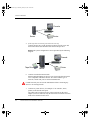
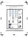


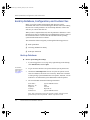


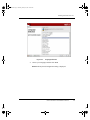
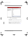
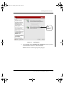

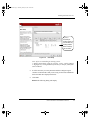

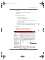
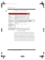


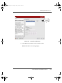


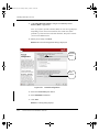


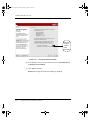
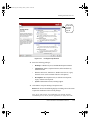


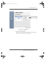
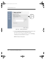
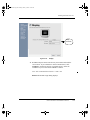
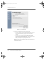

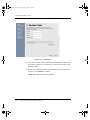


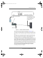


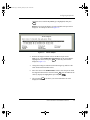


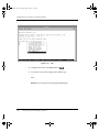
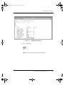
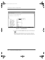
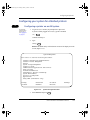


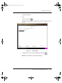
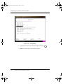
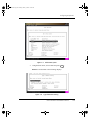
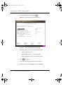

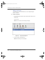

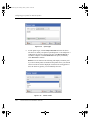
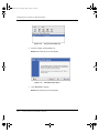


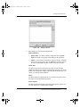


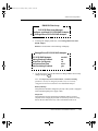

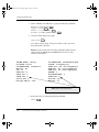

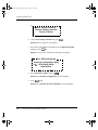

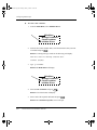


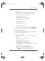
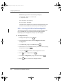
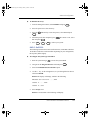

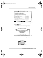


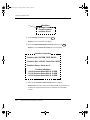
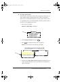
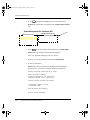


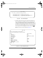


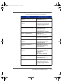
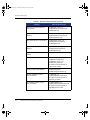
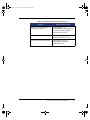


![20 [7] Don Libes, “Using expect to Automate Systems Administration](http://vs1.manualzilla.com/store/data/005773716_1-68a79e060d9ea16881001f4ab808f924-150x150.png)