1
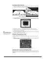
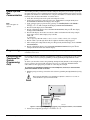
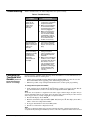
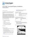
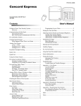
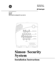
' $737RXFKSDG'LVSOD\ *(,QWHUORJL[ ,QVWDOODWLRQ,QVWUXFWLRQV ZZZ*(,QWHUORJL[FRP Product Summary 'RFXPHQW1XPEHU5HY$ 2FWREHU The ATP1000 lets you control all programming and operation of compatible security systems (see the “Specifications” section). The large 2-line, 16-character display provides easy to read messages to indicate the current status of the system. The touchpad includes police, fire, and auxiliary panic buttons that can be activated anytime. A built-in speaker provides alarm, status, and button-press sounds. A swingdown door reveals a label with basic system operating commands. The door can be removed by simply opening it past its stop point. The door can also be reattached later if desired. Tools and Equipment Needed 0RGHO1R Installation • • • • • 4-conductor, 22- or 18-gauge wire Screwdriver #6 screws and anchors (included) Panhead screws for gang box installation Saw or utility knife for cutting wallboard Guidelines • • • • • Mount the touchpad in an environmentally controlled area (32°F to 120°F/0°C to 49°C). When mounting the touchpad, allow at least 3 inches below it for the swing-down cover. Do not exceed the maximum available power. See the panel installation instructions for maximum available power. Table 1 describes the power used by the touchpad. Table 2 describes the maximum wire lengths allowed between the touchpad and the panel. Table 1: Touchpad Power Usage Current (mA) Conditions 110 Maximum alarm current with the buzzer sounding and the touchpad illuminated from a button press 60 Typical operation 12 Power saving mode (no panel AC power) Table 2: Maximum Touchpad Wire Lengths Wire Gauge (Unshielded or Shielded) Max. Touchpad Wire Length Between Touchpad and Panel 18 750 feet 22 300 feet 1 Installing the Mounting Plate 1. Separate the mounting plate from the touchpad by first loosening the screw, then lift the touchpad away from the mounting plate (see Figure 1). Loosen screw, then lift touchpad. Figure 1. Separating the Touchpad from the Mounting Plate 2. For wall mounting, place the mounting plate on the wall and mark the mounting holes (see Figure 2). Be sure to leave a 3-inch clearance below for the touchpad door to open. Mounting Holes Mounting Holes Figure 2. Mounting Hole Locations Note Do not overtighten screws or the mounting plate may bind and prevent the touchpad from mounting properly. 3. Insert anchors into the wall at the marked locations where studs are not present. 4. Align the mounting plate holes with the wall or gang box screw holes and secure the back plate using the screws provided. 5. For wall-mount installations, cut a hole in the wall in the wire access area of the mounting plate to pull the wiring cable through. Wiring the Touchpad to the Panel 1. Remove panel AC and backup battery power. 2. Run a 4-conductor, 18- to 22-gauge wire from the panel to the touchpad location (see Table 2). 3. Connect the touchpad +12V, BUS A, BUS B, and GND terminals to the matching panel terminals (see Figure 3 for touchpad terminal identification). GND BUS B BUS A +12V Figure 3. Touchpad Wiring Connections Attaching the Touchpad to the Mounting Plate Align the tabs at the top of the mounting plate with the slots on the touchpad and swing the touchpad bottom toward the mounting plate. Gently tighten the screw into the bottom of the touchpad. 2 ATP1000 Touchpad/Display Installation Instructions Power Up and Bus Communication Note Steps 3 through 9 are optional. After making all wiring connections from the touchpad to the panel, you are ready to power up the panel and verify correct communication between the touchpad and the panel. Upon power up, the panel scans the bus for connected devices, assigns a unit number to each bus device, and automatically learns the device ID number of each bus device. 1. Verify that all wiring between the panel and touchpad is correct. 2. Connect the panel battery and restore AC power. Alphanumeric touchpads briefly show SCANNING BUS DEVICES, then display date and time. 3. At the touchpad, enter program mode by pressing 8 + installer/dealer code (default = 4321) + 0 + 0. The touchpad should display SYSTEM PROGRAMMING. 4. Press ƒ and the display shows SECURITY. 5. Press A or B until the display shows ACCESSORY MODULES, then press ƒ. The display should read BUS DEVICES. 6. Press ƒ. The display shows the lowest device address and its ID. The following example shows what a device address display may look like: UNIT - ID 0—02110185* *The 8-digit SuperBus ID number is also located on a label on back of the touchpad. 7. Press A or B to cycle through all bus device addresses until the touchpad appears. 8. After verifying the touchpad device ID, press ‚ repeatedly until the display shows SYSTEM PROGRAMMING. 9. Press A or B until the display shows EXIT PROGRAMMING READY, then press ƒ. The touchpad should show the date and time display. Programming To program options for the newly installed touchpad (such as key beeps) see the specific panel installation instructions. Connecting the Touchpad for System Programming Only For installations that don’t include an alphanumeric touchpad as a permanent part of the system, you can connect one for system programming to the Programming Touchpad Header on the panel. To do this you must first connect a Programming Touchpad Cable (60-791) to the touchpad wires (see Programming Touchpad Cable Installation Instructions—466-1604, included with the cable). Then, use the appropriate procedure for connecting the touchpad. To connect a programming touchpad to a Concord Express, Concord, or Concord Ultra panel with software version 2.0 or later: 1. With the panel powered up, connect the cable to the Programming Touchpad Header (see Figure 4). ! When using the ATP1000 as a programming touchpad, be careful not to touch its circuit board which is exposed on the backside. Caution . T e s t S y s te m O ff W e e k ly A p re s s b o th p re s s b o th p re s s b o th A w a y 2 S ile n t 4 5 6 F e a tu re s S y s te m M e n u 3 P a g e r 7 8 9 S ta tu s L ig h ts B y p a s s 0 # C D S ta y 1 N o D e la y B * PROGRAMMING TOUCHPAD CABLE (60-791) 8642G29A.DSF Figure 4. Connecting a Programming Touchpad—Concord Express Shown, Concord Similar 2. Activate the touchpad by pressing 8 + CODE + 0 + 2. ATP1000 Touchpad/Display Installation Instructions 3 3. Enter program mode by pressing 8 + installer/dealer CODE + 0 + 0 and program the panel using the panel Installation Instructions. 4. When programming is completed, simply disconnect the programming touchpad. To connect a programming touchpad to a Concord panel with software versions 1.0–1.6: 1. Disconnect AC and backup battery power. 2. Connect the cable plug onto the panel Programming Touchpad Header pins (see Figure 5). 3. Reconnect the AC and backup battery power. The touchpad briefly displays ***********, SCANNING BUS DEVICES, then shows a time and date display. Note If the touchpad does not respond as described in step 3, there may be a bus conflict. To correct this, change the touchpad unit number as described in the section “Changing the Touchpad Unit Number.” Removing the programming touchpad from Concord panels with software versions 1.0–1.6: To prevent a trouble condition, you must delete the programming touchpad unit number from Concord panel memory before disconnecting it. 1. After programming is completed, return to the ACCESSORY MODULES menu, then press ƒ. The display should read BUS DEVICES. 2. Press ƒ. The display shows the lowest unit number and its device name. 3. Press A or B until the display shows the programming touchpad unit number. 4. Press D to delete the device and its unit number from panel memory. The display shows: UNIT - TYPE 14-NONE 5. Exit program mode and disconnect the programming cable from the panel header. Testing Note Contact the central monitoring station before activating alarms, to avoid dispatching local police and fire departments. Test the touchpad by arming/disarming the system, activating the touchpad panics, bypassing sensors, and by turning chime and lights on/off to verify correct operation. Refer to the panel User’s Manual for complete system operating instructions. Adjusting Display Brightness and Contrast The touchpad display can be adjusted for easier viewing to help compensate for lighting conditions in the touchpad location. The brightness adjustment lightens or darkens the background. The contrast adjustment lightens or darkens the text. To adjust display brightness: 1. Enter user programming mode by pressing 9 + user, partition, or system master CODE. The display shows SYSTEM MENU, then TIME AND DATE (Concord panels with software versions 1.0–1.6 display USER CODES.) 2. Press B until the display shows OPTIONS, then press ƒ. The display shows DOWNLOADING ON/OFF (current setting). 3. Press B twice and the display shows TOUCHPAD BRIGHTNESS 2 (default setting). 4. Enter a setting from 0 (darkest background) to 3 (brightest background), then press ƒ. 5. The display flashes the entered selection, then stops after pressing ƒ and displays the new setting and brightness level. 6. Exit user programming mode. To adjust display contrast: 4 1. Enter configuration mode by pressing the D and 6 buttons together for at least two seconds. The display shows DA nnn. 2. Press and release the 1 and 2 buttons together repeatedly, until the desired contrast level is displayed. 3. Press ‚ and the display briefly shows DONE, then shows the time and date. ATP1000 Touchpad/Display Installation Instructions Troubleshooting Table 3 describes what to do if the touchpad does not operate correctly. Table 3: Troubleshooting Problem Changing the Touchpad Unit Number (Concord Panels with Software Version 1.0-1.6 Only) Action/Solution Touchpad doesn’t power up (no display and no beeps when buttons are pressed). 1. Check for correct wiring connections at touchpad and panel terminals. 2. Make sure panel battery is connected correctly and that the panel transformer is plugged in. 3. Make sure panel transformer is not plugged into an electrical outlet controlled by a switch. Relocate transformer to an unswitched outlet location, if necessary. Touchpad display appears blank, but beeps sound when buttons are pressed. 1. Check the touchpad display contrast setting. It may be set to 0 (no display). Touchpad display shows a flashing *, indicating a trouble condition and system doesn’t respond to commands from touchpad. 1. Check for correct bus wiring connections (green and white wires) at touchpad and panel terminals. 2. Make sure touchpad unit number is set to a different number than all other bus devices. If necessary, change the touchpad unit number (see procedure on this page). (Concord panels with software versions 1.01.6 only.) Use the following guidelines when changing device unit numbers to avoid communication conflicts between bus devices and the panel: • • All bus devices with DIP switches (LED Touchpads, ESMs, HIMs, etc.) must be set to the desired unit number before applying power and entering program mode. Whenever possible, assign touchpad unit numbers before all other panel programming. To change the touchpad unit number: 1. At the touchpad, press and hold the D and 6 buttons together for at least 2 seconds. The display should show DA n, where n is the current touchpad unit number (000 - 015). Note At this time, the touchpad is in configuration mode and no longer communicating to the panel. The system may immediately indicate a bus failure. Ignore the failure and continue with the procedure. The bus failure will clear after successfully changing the touchpad unit number. 2. Press ƒ. The display shows ENTER _. 3. Enter the desired three digit unit number (000 - 015), then press ƒ. The display shows DA n, where n is the new touchpad unit number. 4. Do not use unit number 15 in Concord RF systems. 5. Press ‚ to exit from the configuration mode. Note If the new touchpad unit number was previously learned by the panel, communication between the touchpad and the panel begins immediately. However, if the new touchpad unit number has never been ATP1000 Touchpad/Display Installation Instructions 5 learned by the panel, continue with step 6. 6. Force the panel to scan bus devices as follows: For systems where this is the only installed touchpad, remove panel AC and battery power, then re-apply power. For systems with more than one touchpad, go to another system touchpad and enter 8 + installer/dealer CODE (default = 4321) + 0 + 1. The display shows SCANNING BUS DEVICES, then a time and date display. The touchpad and all other bus devices should operate correctly and any bus failures should be cleared. Note If the panel still indicates a bus failure the panel may have previously learned a unit number that is no longer used by any bus device. See the specific panel Installation Instructions for more information on deleting unused unit numbers. Specifications Compatibility: ...........................Concord, Concord Express, Concord Ultra Power Requirements: ................12 VDC nominal (See Table 1 for additional power requirements.) Temperature Range: ..................32°F (0°C) to 120°F (49°C) Maximum Humidity: ................95% relative, non-condensing Dimensions: ..............................5.0” x 4.50” x 0.75” (L x W x D) UL Listings (all applied for): .....UL 985 Household Fire Warning System Units ...................................................UL 1023 Household Burglar-Alarm System Units ...................................................UL 1610 Central Station Burglar-Alarm Units (Commercial Burglary) Note See specific panel Installation Instructions for complete UL installation requirements for the system you are installing. Notices FCC Part 15 Information to the User Changes or modifications not expressly approved by GE Interlogix can void the user’s authority to operate the equipment. FCC Part 15 Class B This equipment has been tested and found to comply with the limits for a Class B digital device, pursuant to part 15 of the FCC Rules. These limits are designed to provide reasonable protection against interference in a residential installation. This equipment generates, uses, and can radiate radio frequency energy and, if not installed and used in accordance with the instructions, may cause harmful interference to radio communications. However, there is no guarantee that interference will not occur in a particular installation. If this equipment does cause harmful interference to radio or television reception, which can be determined by turning the equipment off and on, the user is encouraged to try to correct the interference by one or more of the following measures: Reorient or relocate the receiving antenna. Increase the separation between the equipment and receiver. Connect the affected equipment and the panel receiver to separate outlets, on different branch circuits. Consult the dealer or an experienced radio/TV technician for help. ) ©2003 GE Interlogix. Concord is a trademark of GE Interlogix. All other names are trademarks of their owners. All rights reserved. 6 *(,QWHUORJL[ 6HFRQG6WUHHW1RUWK 1RUWK6DLQW3DXO01 86$&DQDGD 7HFKQLFDO6XSSRUW ATP1000 Touchpad/Display Installation Instructions