1
P300M USER’S
MANUAL
1
2
3
4
5
Contents
Introduction .................................................................................. 3
1.1 Overview ............................................................................. 3
1.2 Product Features ................................................................... 3
1.3 Product Specifications ............................................................. 4
Getting Started .............................................................................. 5
2.1 Connecting to the Network ........................................................ 5
2.2 Connecting to the serial device................................................... 5
2.3 Connecting to the power .......................................................... 5
2.4 RESET button ....................................................................... 5
2.5 LED indicators ...................................................................... 6
Operation mode............................................................................. 7
3.1 TCP Server Mode .................................................................. 7
3.2 TCP Server Ext Mode ............................................................. 7
3.3 Telnet Server Mode ................................................................ 7
3.4 TCP Client Mode ................................................................... 7
3.5 TCP Client Ext Mode............................................................... 7
3.6 UDP Server Mode .................................................................. 8
3.7 UDP Client Mode ................................................................... 8
3.8 VCOM Server Mode................................................................ 9
3.9 RTU Slave Mode ................................................................... 9
3.10
RTU Master Mode ............................................................... 9
3.11
Disabled Mode ................................................................... 9
Configuring Device ....................................................................... 10
4.1 WEB Console Configuration .................................................... 10
4.1.1 System Information ....................................................... 10
4.1.2 Networking Settings ...................................................... 11
4.1.3 Mode Settings ............................................................. 11
4.1.4 Serial Port Settings ....................................................... 12
4.1.5 System Settings........................................................... 13
Virtual Serial Port ......................................................................... 16
5.1 Install Software.................................................................... 16
5.2 Virtual Serial Port Configuration................................................ 17
5.2.1 Add Serial Port ............................................................ 17
5.2.2 Delete Serial Port ......................................................... 19
5.2.3 Start Connection .......................................................... 19
5.2.4 Stop Connection .......................................................... 19
5.2.5 Restart Connection ....................................................... 19
5.2.6 Restart All Connections.................................................. 19
5.2.7 Clear Counters ............................................................ 19
5.3 Tools ................................................................................ 19
5.3.1 Monitor Data ............................................................... 19
5.3.2 Scan Online Devices ..................................................... 20
1 INTRODUCTION
1.1 OVERVIEW
P300M serial port server is designed to make your serial devices Internet ready
instantly. P300M device server makes it the ideal choice for connecting your
RS-232/485 serial devices, such as card readers, payment terminals, LED wall, PLC,
sensors, base station monitor devices, etc, to an IP-based Ethernet LAN, making it
possible for your software to access serial devices remotely located on a local LAN,
even on the Internet.
P300M supports several operation modes, including TCP Server, TCP Client, UDP
Server/Client, Pair Connection, ensuring the compatibility of network software that
uses a standard network API (Winsock, BSD Sockets). In addition, P300M’s Virtual
COM/TTY drivers allow you to set up your COM/TTY port software to work over a
TCP/IP network in no time. This excellent feature preserves your software investment
and lets you enjoy the benefits of networking your serial devices instantly.
1.2 PRODUCT FEATURES
Higher price-performance ratio in its class of RS-232/RS-485 serial port servers.
32 bits ARM Cortex-M3 CPU.
3 ports of RS-232, support RTS/CTS,DTR/DSR flow control.
3 ports of RS-485 with terminal block, easy for field deployment.
ESD 1.5KV protection,lighting stroke protection.
Wide power input voltage ranging from 6 to 36 VDC, Terminal block power with
polarity reverse protection.
Run the independently developed Real Time OS optimized for networking traffic.
Support Telnet Server、TCP Server、TCP Client、TCP Client Ext、UDP Server、
UDP Client、VCOM Server operation mode. TCP Client and UDP Client modes
support DNS server;
Support ModBus RTU Slave, RTU Maskter mode, and RTU Slave supports
max 6 connections.
Any two serial ports could be locally connected via TCP Server and TCP
client mode.
Configuration via WEB/Telnet/serial console.
Windows /Linux virtual serial port utility.
Upgrading firmware through tftp protocol, greatly improve the maintenance of
device at remote field.
1.3 PRODUCT SPECIFICATIONS
Ethernet
RS-232
RS-485
Software
10/100Mbps RJ45
Port number:
3
Interface:
Male DB9
Max baud rate: 912.6Kbps
Data:
5,6,7,8
Parity:
None, Even, Odd, Space, Mark
Stop:
1,2
Flow control:
RTS/CTS, DTR/DSR
Signal:
TxD,RxD,RTS,CTS,DTR,DSR,DCD,GND
ESD:
2KV
Port number:
3
Interface:
3.81mm terminal block
Max baud rate: 230.4 Kbps
Data:
5,6,7,8
Parity:
None, Even, Odd, Space, Mark
Stop:
1,2
Signal:
Data+,Data-,GND
ESD:
2KV
Max slaves:
32
Protocol:
IP,TCP,UDP,ICMP,DHCP,TFTP,TELNET,DNS,HTTP
Tools:
vComMgr virtual serial port tools
OS:
Windows XP/7/2003,
Linux Kernel 2.4.x, 2.6.x, 3.0.x
Aluminum case (1 mm)
6 to36 VDC
-40C ~ 80°C
Mechanical
Power
Operating
temperature
Notes: User can only select one of RS-232/RS-485 interfaces to connect your device.
WEB console provides the way for configuration, for details please refer to the chapter
“Mode Settings”.
2 GETTING STARTED
2.1 CONNECTING TO THE NETWORK
P300M’s default IP address is 192.168.1.222.Please visit http://192.168.1.222 to
access P300M. Both user name and password are admin.
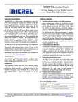
2.2 CONNECTING TO THE SERIAL DEVICE
Connect the serial data cable between the P300M and the serial device. User must
select RS-232/RS-485 interface via WEB console when the corresponding port is
connected to serial device. For details, please refer to the chapter “Mode Settings”.
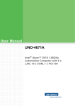
DCD RxD TxD DTR GND
1
2
6
3
7
5
4
8
9
DSR RTS CTS RI
DB9 Male
2.3 CONNECTING TO THE POWER
Connect the 6-36 VDC power line with the P300M’s terminal block. If the power is
properly supplied, all Rx/Tx LEDs will show a blinking green color until the system is
ready, at which time the Rx/Tx LEDs will be off.
Notes:
Grounding and wire routing helps limit the effects of noise caused by
electromagnetic interference. Run the ground connection from the ground
screw to the grounding surface prior to connecting devices.
2.4 RESET BUTTON
When user forgets password or IP address, and wants to restore the factory settings,
the reset button is the simplest way to accomplish that. When P300M powers on,
please press reset button for at least 5 seconds, all three Rx/Tx LEDs will blink one by
one until the factory settings are restored.
2.5 LED INDICATORS
The top panel has four LED indicators, as described as the following table
ID
Name
Action
Specification
1
COM3
Rx/Tx
Blink
Off
2
COM2
Rx/Tx
Blink
Off
3
4
COM1
Rx/Tx
PWR
Blink
COM3 RS-232/RS-485 is sending or receiving
data.
No data.
COM2 RS-232/RS-485 is sending or receiving
data.
No data.
Off
COM1 RS-232/RS-485 is sending or receiving
data.
No data.
Solid Green
Power on.
Off
Power off.
LED group specification:
Group
Action
Slowly
blinking
Fast
blinking
COM3 Rx/Tx
COM2 Rx/Tx
Solid green
COM1 Rx/Tx
Specification
System is booting, slowly blink for 3 seconds.
System is upgrading firmware.
System is at runtime state, and waits fro serial
console input at COM1. The Rx/Tx LEDs will be
solid green for 3 seconds.
Blinking one System is restoring factory settings, the reset must
by one
be pressed for at least 5 seconds.
3 OPERATION MODE
3.1 TCP SERVER MODE
In TCP Server mode, the P300M provides a unique IP/Port address on a TCP/IP
network, each TCP local port corresponds to a P300M's serial port. The P300M waits
passively to be connected by the host computer, allowing the host computer to
establish a connection with and get data from the serial device. This operation mode
also supports up to 6 simultaneous connections, so that multiple hosts can collect
data from the same serial device—at the same time. The data is transparently sent
and received by P300M.
3.2 TCP SERVER EXT MODE
The difference with TCP Server mode is that it only supports master/slave mode, TCP
client runs as a master and sends command to serial port server, then serial port
server sends the command to serial device working as a slave, and waits for the
response, for details about response timeout setting, please refer to chapter “Serial
Port Settings”. After serial port server receives response data, it ONLY sends the
data the the TCP client which sends the command, it will not copy the data to other
clients.
3.3 TELNET SERVER MODE
Console management is commonly used by connecting to RS-232 ports of routers,
switches, and UPS units. Telnet server works similar with TCP Server, except that it
parses tenet protocol.
3.4 TCP CLIENT MODE
In TCP Client mode, the P300M can actively establish a TCP connection to a
pre-defined host computer before serial data arrives. After the data has been
transferred, the P300M will disconnect from the host computer by using the TCP alive
check time. The keep-alvie time interval is 10 seconds, and the total timeout is 2
minutes. P300M can also connect to remote host computer via DNS, such as the
following settings.
3.5 TCP CLIENT EXT MODE
“TCP Client EXT” mode is the extended mode of “TCP Client”. When TCP Client
connects to remote host computer at Internet, both source IP address and source port
may be translated to a public IP and port (NAT). So host computer can’t distinguish a
serial port through IP and port when this kind of application is encountered.
As soon as TCP client connects to host, P300M will send the following 18 bytes of
data for host to detect serial port corresponding to the P300M.
Byte 0
Byte 1
Byte 2
Byte 3 Byte 4 - Byte 15
Byte 16
Byte 17
0xAA
0xFB
Length 1
Serial Number
Serial Port
CRC
Number
Byte 0
Preamble code 0xAA
Byte 1
Preamble code 0xFB
Byte 2
Payload length, it calculates from byte 3 to the byte before CRC. In this
case , the payload length is 14。
Byte 3
Command code, it is always 1.
Byte 4-15 SN in ASCII format , the size is 12 bytes.
Byte 16
Serial port number, which starts at 1.
Byte 17
CRC checksum of the whole payload,calculates from byte 3 to the byte
before CRC。The CRC is the two’s complement of sum of all bytes in 8 bits. The
following code is an example of crc verification in C language.
unsigned char crc, length, i, temp;
if((buf[0] != 0xAA) || (buf[1] != 0xFB) || (buf[3] != 1))
{
/* Return fail code */
return;
}
len = buf[2];
temp = 0;
for(i = 0; i < len; i++)
{
temp += buf[3+i];
}
crc = ~temp;
if(crc != buf[17])
{
/* Return fail code */
return;
}
/* CRC is correct, do whatever you want to do next. */
3.6 UDP SERVER MODE
Compared to TCP communication, UDP is faster and more efficient. UDP Server
receives data from UDP client and sends it to serial device.
3.7 UDP CLIENT MODE
UDP Client receives data from serial device and send it to host computer by IP
address and port, which are set at web page. The target address could be an IP
address, broadcast IP address, network segment IP address, or a domain name. for
example, if the target IP address 10.1.1.1-50, it denotes that the serial port server will
send the data one by one through UPD to the IP 10.1.1.1 to 10.1.1.50. If the target
address is only one host, there is no need to add the subfix -XXX. Be noticed that two
consecutive UPD packet interval is about 1 ms, if user wants to send data to 50 hosts,
it will take about 50ms to complete this action. For details, please refer to “Mode
Settings”.
3.8 VCOM SERVER MODE
Compared to TCP Server mode, VCOM Server mode especially handles RTS/CTS,
DTR/DSR flow control and baudrate settings, and it is used with virtual serial port
vComMgr utility together. vComMgr runs as a TCP client. The driver establishes a
transparent connection between host and serial device by mapping the IP:Port of the
P300M’s serial port to a local COM/TTY port on the host computer. When the
connection is successfully established, and software at host computer opens the
virtual serial port, all configurations will be synchronized with serial port server.
3.9 RTU SLAVE MODE
ModBus RTU Slave mode is used to connect to the serial device which runs as RTU
Slave. Serial port server runs as a TCP Server.
3.10 RTU MASTER MODE
ModBus RTU Master mode is used to connect to the serial device which runs as RTU
Master. Serial port server will connect to the remote TCP Server, which is also called
Modbus TCP Slave.
3.11 DISABLED MODE
When the Operation Mode for a particular port is set to Disabled, the port will be
disabled. If a serial port is not used, it is recommended that port be configured with
Disabled.
4 CONFIGURING DEVICE
User could select web console or serial console to configure P300M. The web
console is the most user-friendly way to configure the P300M. Serial console is mainly
used to configure P300M’s networking.
4.1 WEB CONSOLE CONFIGURATION
Please open your web browser and input http://192.168.1.222 , the browser will
prompt a dialog box to let you input user name and password; both user name and
password are admin. The following snapshot shows the page in Google Chrome
browser.
4.1.1 SYSTEM INFORMATION
“System Information” page shows P300M’s basic settings as the following
pictures.
Max Response Time is measured during the communication. It is a very important
reference to set Response Timeout at the Serial Port Settings page. This parameter is
only valid when the corresponding serial port operates as RTU Slave, RTU Master or
TCP Server Ext mode.
4.1.2 NETWORKING SETTINGS
This page configures P300M’s networking settings. If you accidently set an invalid
IP and reboot the device, you could press reset button for 5 seconds to restore factory
settings, or configure the networking via serial console, for more information, please
refer to chapter “Serial Console Configuration”. If the IP address is retrieved via
DHCP( Dynamic IP), the vComMgr utility provides the feature to scan online devices.
Notes:
The settings in this page take effect after device reboots.
4.1.3 MODE SETTINGS
Each P300M’s serial port support RS-232 and RS-485. Before connecting serial
device to P300M, user should select the interface and operation mode. The operation
modes are specified in details in chapter “Operation Mode”.
“Local Port” and “Server Port” are a bit confusing. When operation mode is configured
as server mode, P300M will listen at the port and accept incoming connection and
data. When operation mode is configured as client mode, the local port will be bound
as source port. Remote host computer may identify the serial port by IP and source
port. If local port’s value is zero, it means that user would let system automatically
generate UPD/TCP source port.
P300M also support connecting to server by DNS when the operation mode is client.
4.1.4 SERIAL PORT SETTINGS
RS-232 baud rate supports 50bps to 921600bps, and RS-485’s max baud rate is
230400bps.Data bits are 5,6,7 and 8. Stop bits are 1 and 2. Parity options are None,
Even, Odd, Space and Mark. “”
Flow controls mean hardware flow control. There are NONE, CTS, DSR, DSR/CTS
for selection.
NONE, no flow control. (Factory default)
CTS, Signal RTS (Request To Send - from P300M) and CTS (Clear To Send
- from the Serial Device) are used to control. In most Asynchronous
situations, RTS and CTS are constantly on throughout the communication
session. In this flow control mode, P300M sends data to serial device only it
detects CTS voltage level is high, 3-15VDC.
DSR, Signal Data Set Ready (DSR) is an indication from Serial Device (i.e.,
PLC) that it is on. Similarly, DTR indicates to Serial Device that the P300M is
on. In this flow control mode, P300M sends data to serial device only it
detects DSR voltage level is high, 3-15VDC.
DSR/CTS, In this flow control mode, P300M sends data to serial device only
it detects both DSR and CTS voltage level is high, 3-15VDC.
Be noticed that user should connect P300M’s RTS signal to Serial Device’s CTS
signal, and P300M’s DSR signal to Serial Device’s DTR signal when flow control is
selected. Please refer to the chapter “Connecting to the serial device” for .DB9
signal definition.
RX Timeout: The maximum time allowed elapsing between the arrivals of two bytes
on the Serial Port line, in milliseconds. During a Read operation, the time period
begins when the first byte is received. If the interval between the arrivals of any two
bytes exceeds this amount, the Read operation is completed and any buffered data is
sent to TCP/UDP stack. Zero means Read operation returns immediately.
TX Timeout: The maximum time allowed elapsing between the arrivals of two bytes
on the TCP/UDP stack, in milliseconds. During a Write operation, the time period
begins when the first byte is received. If the interval between the arrivals of any two
bytes exceeds this amount, the Write operation is completed and any buffered data is
written to serial port line. Zero means Writing buffered data immediately.
Response Timeout: The original Modbus protocol was not designed for
simultaneous requests or simultaneous masters, so only one request on the network
can be handled at a time. When a master sends a request to a slave, no other
communication may be initiated until after the slave responds. The Modbus protocol
specifies that masters use a response timeout function to identify when a slave is
nonresponsive due to device or line failure. This function allows a master to give up
on a request if no response is received within a certain amount of time.
We provide a simple way to set Response Timeout. Our serial port server will
measure each response time and save the max one, which is displayed at the System
Information page. So when user starts the serial port server at the first time, we
suggest that let Master/Slave communicate for a long time and observe the max
response time, here say 156ms, so 180ms is a good Response Timeout to be set,
extra 24ms is reserved to reduce risk.
4.1.5 SYSTEM SETTINGS
This chapter specifies how to set language, reboot device, restore factory settings,
etc.
4.1.5.1 LANGUAGE SETTINGS
P300M currently supports two languages, Simplified Chinese and English. After
saving the selected language, please refresh the page, or press F5 button to make
the browser load the new language.
4.1.5.2 REBOOT DEVICE
Press the “Reboot Device” to reboot the system.
4.1.5.3 RESTORE FACTORY SETTINGS
Press the “Restore Factory Settings”button to load default settings. Be noticed that
the previous settings will be lost after this operation.
4.1.5.4 WEB ADMINISTRATION
For security reason, user may need to change http server’s port. After port is changed,
you should reboot the system, and then input http://192.168.1.222:XXXX in your web
browser. XXXX is the new port.
4.1.5.5 CHANGE PASSWORD
Input New Administrator and new Password to change.
4.1.5.6 UPGRADE FIRMWARE
Upgrading firmware through network greatly improve the maintenance of serial port
server at field. Before upgrading firmware, please download firmware file, say
R3.0.05.bin, and save it in a directory. Then download the tftp server, we strongly
recommend user run tftd32 as tftp server, which is open source. User could visit its
website http://tftpd32.jounin.net/ to freely download it. The main UI is as the
following. Press the “Browse” button to select the directory where the firmware file is
saved, the tftp server is easily setup.
Then input the firmware file name and tftp server IP address in the webpage as the
following page, press “Upgrade”button, then P300M will automatically download
firmware and upgrade it. In the upgrading process, all three Rx/Tx LEDs will fast blink.
After upgrading successfully finish, Rx/Tx LEDs will be solid green for 3 seconds, then
be turned off. The whole process takes about 20 seconds, be patient to wait. Finally
click on the “System Information” page to check the newly upgraded version.
Notes:
Don’t power off P300M when it is in upgrading process.
5 VIRTUAL SERIAL PORT
The virtual serial port utility vComMgr supports 32 Bits Microsoft Windows series,
Windows XP/WIN7/2003 Server, and tty driver supports Linux kernel 2.6.x and 3.0.x.
5.1 INSTALL SOFTWARE
Unzip the vComMgr-2.x.zip and run the Setup.exe to install the utility.
Click on the menu [Start] -> [Programs] -> [vcom] -> [vComMgr], the vComMgr runs
as the following.
Notes:
vComMgr takes high privilege to install serial port driver, Some free
anti-virus software may regard it as virus by mistake. Be aware of the
incorrect warning messages.
5.2 VIRTUAL SERIAL PORT CONFIGURATION
5.2.1 ADD SERIAL PORT
Before add a virtual serial port, please set the corresponding P300M’s serial port
operation mode with “VCOM Server”as the following.
vComMgr maps the serial port server’s port to local serial port through IP address
and port. “Server IP” not only supports IP address, but also supports DNS.
Be noticed that the serial port driver will be installed twice. The installation process is
identical as the following.
After the driver is installed, vComMgr will automatically connect to P300M. Each time
host computer starts up, the connection will be established. The virtual serial port
works only the connection state is “connected”. vComMgr supports adding a max
number of 128 virtual serial ports.
When installing serial port driver at WIN7, the system may prompt a “Windows
Security” warning, be sure to select installing the driver. The warning dialogue box
may be prompted four times, do as the same way.
Notes:
To make all VCOM work correctly, it is strongly recommended to reboot host
computer when installing multiple virtual serial ports.
5.2.2 DELETE SERIAL PORT
Before deleting VCOM, please make sure that no application is opening the serial port,
then select [Device] -> [Delete VCOM] menu to delete the virtual serial port, the whole
process may take several seconds, please be patient to wait.
5.2.3 START CONNECTION
Start connecting to serial port server when the connection is previously stopped.
5.2.4 STOP CONNECTION
Stop the connection. When host computer starts next time, the connection will be also
at the stop state.
5.2.5 RESTART CONNECTION
Restart the connection to serial port server.
5.2.6 RESTART ALL CONNECTIONS
Restart all connections in the list table.
5.2.7 CLEAR COUNTERS
Clear RX and TX counters.
5.3 TOOLS
5.3.1 MONITOR DATA
Select the serial port to be monitored, then press the menu [Tool] -> [Monitor Traffic],
a dialogue box will we displayed as the following. This tool is very useful to debug and
trace the communication between application and serial device.
5.3.2 SCAN ONLINE DEVICES
Compare with the traditional online devices scanning, the following feature to scan
online devices could cross different subnets.