1
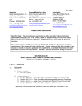
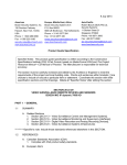
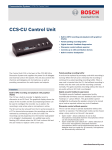
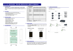
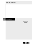
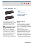
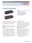
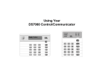
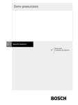
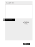
LTC 8950 Series
User Manual
EN System Supervisor
Version 2.8
LTC 8950 Series | User Manual | Contents
EN | 2
Table of Contents
1
1.1
2
3
3.1
3.2
3.3
3.4
3.5
3.6
3.7
3.8
3.9
3.10
4
4.1
4.2
4.3
4.4
4.5
SYSTEM SUPERVISOR . . . . . . . . . . . . . . . . . . . . . . . . . . . . . . . . . . . . . . . . . . . . . . . . . . . . . . . . .3
Overview . . . . . . . . . . . . . . . . . . . . . . . . . . . . . . . . . . . . . . . . . . . . . . . . . . . . . . . . . . . . . . . . . . . . . .3
TERMINOLOGY . . . . . . . . . . . . . . . . . . . . . . . . . . . . . . . . . . . . . . . . . . . . . . . . . . . . . . . . . . . . . . .3
SYSTEM SUPERVISOR CONTROLS AND DISPLAYS . . . . . . . . . . . . . . . . . . . . . . . . . . . . . . .4
System Menu . . . . . . . . . . . . . . . . . . . . . . . . . . . . . . . . . . . . . . . . . . . . . . . . . . . . . . . . . . . . . . . . . . .4
Minimize . . . . . . . . . . . . . . . . . . . . . . . . . . . . . . . . . . . . . . . . . . . . . . . . . . . . . . . . . . . . . . . . . . . . . .4
Shut Down . . . . . . . . . . . . . . . . . . . . . . . . . . . . . . . . . . . . . . . . . . . . . . . . . . . . . . . . . . . . . . . . . . . . .4
Status Display . . . . . . . . . . . . . . . . . . . . . . . . . . . . . . . . . . . . . . . . . . . . . . . . . . . . . . . . . . . . . . . . . .4
Settings Button . . . . . . . . . . . . . . . . . . . . . . . . . . . . . . . . . . . . . . . . . . . . . . . . . . . . . . . . . . . . . . . . . .4
Allegiant Button . . . . . . . . . . . . . . . . . . . . . . . . . . . . . . . . . . . . . . . . . . . . . . . . . . . . . . . . . . . . . . . . .6
Help Button . . . . . . . . . . . . . . . . . . . . . . . . . . . . . . . . . . . . . . . . . . . . . . . . . . . . . . . . . . . . . . . . . . . .6
Silence Button . . . . . . . . . . . . . . . . . . . . . . . . . . . . . . . . . . . . . . . . . . . . . . . . . . . . . . . . . . . . . . . . . .6
Operating Mode Display . . . . . . . . . . . . . . . . . . . . . . . . . . . . . . . . . . . . . . . . . . . . . . . . . . . . . . . . . .6
Event Log . . . . . . . . . . . . . . . . . . . . . . . . . . . . . . . . . . . . . . . . . . . . . . . . . . . . . . . . . . . . . . . . . . . . . .6
LTC 8900 SYSTEM OPERATION . . . . . . . . . . . . . . . . . . . . . . . . . . . . . . . . . . . . . . . . . . . . . . . . .6
Select Primary, Back-Up or Auto (Auto-Select) Mode Selection . . . . . . . . . . . . . . . . . . . . . . . . . . . .6
Open the LTC 8900 Configuration File in the Allegiant Server Application . . . . . . . . . . . . . . . . . .6
When System Supervisor Becomes Visible . . . . . . . . . . . . . . . . . . . . . . . . . . . . . . . . . . . . . . . . . . . .7
In the Event of a CPU Controller or Network Hub Warning, Malfunction or Failure . . . . . . . . . . .7
To Shut Down the System Supervisor . . . . . . . . . . . . . . . . . . . . . . . . . . . . . . . . . . . . . . . . . . . . . . . .8
Bosch Security Systems | March 2, 2006
EN | 3
LTC 8950 Series | User Manual | System Supervisor
1
SYSTEM SUPERVISOR
1.1
Auto-Select Mode is the mode of operation
selected when the slide switch on the LTC 8901
CPU Bay front panel is in the Auto position. This
allows the System Supervisor to automatically
switch the In-Use and Stand-By CPU to restore
operation of the system in the event of failure of
the In-Use CPU or the Network LAN connected
to it.
•
Primary (CPU and Network) is the CPU and
Network LAN pair activated when the slide
switch on the LTC 8901 CPU Bay front panel is
in the Primary CPU position (also can be
activated when the LTC 8900 is in Auto-Select
mode).
•
Back-Up (CPU and Network) is the CPU and
Network LAN pair activated when the slide
switch on the LTC 8901 CPU Bay front panel is
in the Back-Up CPU position (also can be
activated when the LTC 8900 is in Auto-Select
mode).
•
Data Mirroring is a technique allowing two
CPUs to receive the same data, and the same
updates, so they can be interchanged in the
event of malfunction, with no loss of data or
operator intervention.
•
Network LAN is a term used in the manual and
the software, to denote the operating conditions
of either LAN Hubs or LAN Switch network
devices supplied with the LTC 8900 system.
Overview
The System Supervisor monitors and controls operation
of the LTC 8900 System. When an LTC 8900
configuration file is opened from the Allegiant® Master
Control Software program, and put Online, the System
Supervisor becomes visible. Status of the LTC 8900
System components is graphically displayed in the
Supervisor’s Status Display Window, and operation of
the System can be controlled via the mouse or PC
keyboard. If the Auto-Select operation mode is selected,
failure of the In-Use CPU or the Network LAN
connected to it causes an automatic changeover to the
Stand-By CPU. If the Data Mirroring function has been
operating prior to an In-Use CPU failure, the Stand-By
CPU contains all of the latest System settings, and
operation of the System continues with minimal
disruption. System mode changes and malfunctions that
occur are logged, and can be reviewed in a scrollable
Event Log Window.
2
•
TERMINOLOGY
Some terminology used in the LTC 8900 System, and
on the System Supervisor displays:
•
In-Use indicates the device (CPU or Network
LAN) is currently being used to operate the
System.
•
Stand-By indicates the CPU is fully operational,
and available if the In-Use CPU or the Network
LAN connected to it malfunctions.
•
Primary Mode is the mode of operation
selected when the slide switch on the LTC 8901
CPU Bay front panel is in the Primary CPU
position. This selects the Primary CPU to always
be In-Use, even in the event of failure or
malfunction.
•
Back-Up Mode is the mode of operation
selected when the slide switch on the LTC 8901
CPU Bay front panel is in the Back-Up CPU
position. This selects the Back-Up CPU to always
be In-Use, even in the event of failure or
malfunction.
Bosch Security Systems | March 2, 2006
EN | 4
LTC 8950 Series | User Manual | System Supervisor Controls and Displays
3
3.1
3.4
SYSTEM SUPERVISOR
CONTROLS AND DISPLAYS
System Menu
4.
5.
Status Display
The Status Display graphically indicates the current
status of the Primary and Back-Up CPU Controllers and
Network LANs.
1.
Colors and dashed lines help indicate the status of the
items in the display.
2.
Color/Indicator
Description
Green
The item is functioning normally.
Yellow and Flashing
An item is changing state, or
questionable.
Red, Flashing, and
3.
6.
Failure of an item.
Beeping
Solid Lines
CPU or Network LAN is In-Use.
Dashed Lines
CPU or Network LAN is NOT In-Use.
Battery
A low or dead battery has been
detected in the indicated CPU
Figure 1 System Supervisor Main Screen
Data Mirroring States
Mirroring is ON (from In-Use to
Stand-By CPU).
1. System Menu
2. Status Display
3. Event Log
4. Minimize
5. Shut Down
6. Mode Display
Click System Menu to display a menu with selections
used to minimize, move, or close (Shut Down) the
System Supervisor, and to view the About box of the
System Supervisor (contains copyright and version
number information).
3.2
Minimize
Click the [-] icon at the top right-hand corner to
minimize the System Supervisor, if desired. If an event
occurs causing a Caution or Failure indication on the
Supervisor Status Display, the Supervisor automatically
returns to its original size. When minimized, the color
on the traffic signal, drawn on the icon, reflects the state
of the System.
3.3
Shut Down
Click the [x] icon at the top right-hand corner to shut
down the System Supervisor and end monitored
operation of the LTC 8900. The LTC 8900
Configuration file may also be closed, based on the
state of the Allegiant Master Control Software
application. See LTC 8900 Operation-Shut Down for
more information.
Bosch Security Systems | March 2, 2006
Mirroring is OFF, but possible (from
In-Use to Stand-By CPU).
Mirroring is OFF and is NOT possible
because both CPU’s are not fully
operational.
Figure 2 Status Display
3.5
Settings Button
When Settings is clicked, the System Setting dialog
box is displayed. Use the System Settings dialog box
(shown below) to select the CPU to be used when the
System is operated in the Auto-Select Mode (via the
front panel slide switch on the LTC 8901 CPU Bay),
and to enable Data Mirroring. The System Settings
dialog box is also displayed when the operator initially
moves the front panel slide switch on the LTC 8901 to
the Auto (Auto-Select ) position.
The System Supervisor Settings dialog box is shown
below, followed by descriptions of the controls and
displays. Any selections made while in this dialog box
are only applied when/if OK is clicked.
LTC 8950 Series | User Manual | System Supervisor Controls and Displays
EN | 5
Mirroring function will only be successful if the
problem associated with the original CPU has
been corrected.
Auto-Restore Mirroring Notes:
• The Auto-Restore selection is not persistent
(not saved when the application is closed).
• Auto-Restore defaults to ON.
• Auto-Restore can be enabled in Manual or
Auto mode.
Figure 3 LTC 8900 Settings
•
•
• Auto-Restore is NOT disabled when switching
between Auto and Manual.
Selection of the In-Use CPU: The current
In-Use CPU (if any) is displayed; the user can
accept or change it by clicking on one of the
selections. This selection applies only when the
System is in the Auto-Select Mode of operation.
Enable Data Mirroring: This selection is
available only when both Primary and Back-Up
CPUs are fully operational. When Data
Mirroring is selected, all downloads and updates
made to the In-Use CPU will be Mirrored
(copied) to the Stand-By CPU. Mirroring will be
disabled whenever the Primary, Back-Up or
Auto-Select mode of operation is selected via the
front panel slide switch on the LTC 8901 CPU
Bay, or whenever a failure in Auto-Select Mode
occurs. To re-enable it (if desired), use the
System Settings dialog box.
• If Mirroring is enabled, and Auto-Restore
Mirroring is enabled, and if both CPU's are
online, and mirroring is not being done:
• Auto-restores waits 1 minute, then tries to
re-enable mirroring.
• If the '1 minute' attempt fails, Auto-Restore
will wait 15 minutes before attempting to
Auto-Restore mirroring again (continues
indefinitely).
•
Supervisor Beeping Notes:
• Disable Supervisor Beeping is not persistent
(not saved when the application is closed).
Mirroring Notes:
• The Mirroring selection is not persistent (not
saved when the application is closed).
• Mirroring defaults to off (on App start up).
• Disable Supervisor Beeping defaults to OFF
(beeping NOT disabled).
• Mirroring can be enabled in Manual or Auto
mode (Automatic CPU selection mode).
• Beeping from other applications or from the
OS on the PC are not affected.
• Mirroring is turned off when switching to
manual mode.
CAUTION: Only enable Data Mirroring when
you want to copy and update the data from the
In-Use CPU into the Stand-By CPU. If data in
the In-Use CPU is questionable, you may not
want to copy it to the Stand-By CPU.
• When switching to Auto mode, settings dialog
will come up to allow user to select mirroring
mode.
•
Disable Supervisor Beeping: If this box is
checked, the Supervisor program will not
activate the PC beeping feature when a system
fault occurs. Visual indications and logging of
the fault will operate normally.
Auto-Restore Mirroring: By default, whenever
the system switches over from an In-Use CPU
to the Backup CPU, the Mirroring function will
stop. By selecting this option, the software will
periodically attempt to restore the Mirroring
operation. Of course, restoration of the
Bosch Security Systems | March 2, 2006
•
Help Button: Displays Help Information about
the System Settings dialog box. The [F1] key on
the PC can also be used to invoke the Help
System.
EN | 6
LTC 8950 Series | User Manual | LTC 8900 System Operation
•
•
3.6
Cancel Button: Discards any changes made
and closes the System Settings dialog box.
OK Button: Accepts any changes made and
closes the System Settings dialog box. If any
settings are inappropriate based on the current
System State, warning messages will be
provided, so the user can confirm or change
the settings.
Allegiant Button
When Allegiant is clicked, the Allegiant Master
Control Software application becomes visible and
active, so that changes can be made to the System
Configurations, and to upload, download, etc.
3.7
Help Button
Clicking Help displays information about the System
Supervisor. The [F1] key on the PC can also be used
to invoke the Help System.
3.8
Silence Button
Use the Silence button to stop any flashing or
beeping. New events that cause flashing or beeping
will restart those indications.
NOTE: The Silence button only affects the beeper on
the PC; the LTC 8901 CPU Bay Fault Alarm beeper is
not affected (see the LTC 8901 instructions for
silencing the Fault Alarm beeper using a jumper wire
or switch connected to the rear panel alarm
connector).
If the option in the system settings dialog box is
selected, no beeping will occur, but the flashing
indications will still activate.
3.9
Operating Mode Display
The Operating Mode Display selected by the front
panel slide switch on the LTC 8901 CPU Bay:
• Manual - Primary CPU Mode
The Primary CPU will always be used, even in
the event of failure or malfunction.
•
•
Manual - Back-Up CPU Mode
The Back-Up CPU will always be used, even in
the event of failure or malfunction.
Auto-Select CPU Mode
The user initially selects the CPU to be used
(via the System Settings dialog box), and in the
event of failure, the System Supervisor switches
to the other CPU to restore System operation.
Bosch Security Systems | March 2, 2006
3.10 Event Log
The Event Log keeps a time and date stamped record
of the last several hundred events that occurred during
operation of the System Supervisor. Mode changes,
failures and failure recovery actions are logged in a
scrollable list. The Event Log consists of a scrollable
list of events with the latest event at the top.
The Clear Event Log Button allows the list to be
emptied, for ease of viewing new events (if not
emptied the list discards the oldest events as it fills up).
The Extended Diagnostic Log Event message option
will show more detailed information about changes
made to the System. Generally, this information should
be left off, unless troubleshooting a System problem.
Selecting the option to Write Log Messages To File will
initiate the recording of all event details into a log file
named Super.log on the hard drive.
As more and more events are recorded, the log file
will grow to a maximum size of approximately eight
(8) Megabytes. At that point, the oldest event details
will be discarded as more new event details are
received.
4
LTC 8900 SYSTEM OPERATION
4.1
Select Primary, Back-Up or Auto
(Auto-Select) Mode Selection
Place the front panel slide switch on the LTC 8901
CPU Bay in the desired operating mode (Primary CPU,
Back-Up CPU, or Auto (Auto-Select) mode. In the
Primary or Back-Up modes, the System operates in a
Manual mode. In the Manual mode, the selected CPU
will always be used, even in the event of failure or
malfunction. In Auto (Auto-Select) mode, the System
Supervisor will switch to the Stand-By CPU in the
event of failure or malfunction. The front panel slide
switch on the LTC 8901 CPU Bay can be moved at
any time to change the operating mode of the System.
4.2
Open the LTC 8900 Configuration file
in the Allegiant Master Control
Software Application
Open the Allegiant Master Control Software application,
create or open an LTC 8900 configuration file, and
select Go-Online. (See the Bosch Security Systems
LTC 8059/00 Master Control Software User Manual for
more detailed instructions.) When the Online command is
completed (about 20 seconds), the System Supervisor will
EN | 7
LTC 8950 Series | User Manual | LTC 8900 System Operation
(or 57600 Baud for older model CPUs),
8 data bits, 1 stop bit, no parity, and handshaking,
on the Comm Port used. Note, these
communication settings must also be made in
the Allegiant Configuration tables using the
PARAMETER/COMM PORT/ CONSOLE settings.
become visible (only on the dedicated PC, and when
running the below required configuration).
Some guidelines for creating an LTC 8900 configuration
files for the Allegiant Master Control Software
Application are described below.
For the System Supervisor to operate:
• The Allegiant Master Control Software
Application must be running on the LTC 8900’s
dedicated PC.
•
The LTC 8900 configuration file must specify
(using the Transfer/Communication Setup dialog
box): Current Host as Local, Comm Port 3 for
the Primary CPU, Comm Port 4 for the Back-Up
CPU, 115200 Baud (or 57600 Baud for older
model CPUs), 8 data bits, 1 stop bit, no parity,
and handshaking ON, for Comm Port 3 and Comm
Port 4.
To operate as a Networked Client of an LTC 8900
Host already running per the System Supervisor per
the above:
• The client’s LTC 8900 configuration file must
specify (using the Transfer/Communication Setup
dialog box): Current Host set to the network
address of the Host PC, Comm Port 3 for the
Primary CPU, Comm Port 4 for the Back-Up
CPU, 115200 Baud (or 57600 Baud for older
model CPUs), 8 data bits, 1 stop bit, no parity,
and handshaking ON, for Comm Port 3 and Comm
Port 4.
To operate the LTC 8900 using the dedicated PC, but
without the System Supervisor, or with a single CPU:
• The client’s LTC 8900 configuration file must
specify (using the Transfer/Communication Setup
dialog box): Current Host set to local, Comm Port 3
for the Primary CPU, None for the Back-Up
CPU, and 115200 Baud (or 57600 Baud for
older model CPUs), 8 data bits, 1 stop bit, no
parity, and handshaking ON, for Comm Port 3.
To operate the LTC 8900 without using the dedicated
PC, through the console port on the rear of the
LTC 8901:
• The client’s LTC 8900 configuration file must
specify (using the Transfer/Communication Setup
dialog box): Current Host set to local, specify
any available Comm Port for the Primary CPU,
None for the Back-Up CPU, and 115200 Baud
Bosch Security Systems | March 2, 2006
4.3
When System Supervisor
Becomes Visible
When the System Supervisor starts up, a few failure
messages may appear momentarily on the Status
Screen and in the Event Log. These are due to the
System initializing, and may be erased from the Event
Log using the Clear Event Log button.
The System Supervisor will become visible and begin
to operate in the mode selected by the front panel
slide switch of the LTC 8901 CPU Bay. If Auto-Select
mode has been chosen, the System Settings dialog box
will appear, for selection of the initial In-Use
Controller. The status of the system is constantly
monitored and displayed, and the controls of the
System Supervisor can be used to modify the operation
of the System, and to shut down the System
Supervisor. The front panel slide switch on the
LTC 8901 CPU Bay can be moved at any time to
change the operating mode of the System, or to abort
a System action that is not succeeding.
4.4
In the Event of a CPU Controller or
Network LAN Warning, Malfunction,
or Failure
•
If the Supervisor has been minimized, it will
automatically return to its normal size.
•
The affected System component will flash on
the Status Display (stop via the Silence button).
•
If not disabled in the System Setting dialog box,
the PC will begin beeping during failures. It can
be silenced via the Silence button.
•
An event will appear in the Event Log.
•
The Fault LED on the front panel of the
LTC 8901 CPU Bay for the affected CPU/LAN
pair flashes.
•
The Alarm on the LTC 8901 will sound (silence
via LTC 8901 rear panel connections).
•
The Fault Relay on the LTC 8901 for the
affected CPU/LAN pair will be activated.
LTC 8950 Series | User Manual | LTC 8900 System Operation
•
If in Auto-Select mode and the In-Use CPU or
LAN failed, the Stand-By CPU/LAN pair is
automatically selected.
•
If in Manual mode, the user must correct the
situation or change the operating mode.
Once the problem has been corrected, the System
indications automatically return to normal. If in
Auto-Select mode, the CPU/LAN pair in use will not
switch back to the originally selected In-Use CPU. If
desired, use the System Settings dialog box to reselect
the In-Use CPU.
Below is a sample screen showing a failure of the
Primary CPU while in Auto-Select mode, and the
subsequent Auto-Select of the Back-Up CPU and
Network LAN. The Status Display graphically indicates
the failures, and the currently selected CPU and
Network LAN. Failure and recovery actions are
contained in the Event Log.
Figure 4 Error Message Display
4.5
To Shut Down the System
Supervisor
CAUTION: When the System Supervisor is
shut down, the LTC 8901 will no longer
operate in the Manual or Auto-Select modes of
operation, System monitoring will cease, and
Data Mirroring between the CPUs will be
disabled.
To shut down the System Supervisor, click the [x] icon,
or select Close from the System Supervisor System
Menu. After a confirmation dialog box, the System
Bosch Security Systems | March 2, 2006
EN | 8
Supervisor will shut down. If the Allegiant Master
Control Software application is not visible, the
LTC 8900 configuration file in the Allegiant will
close, and the Allegiant application may close. If the
Allegiant application is visible, the LTC 8900 file must
be manually closed from the Allegiant application. If
the LTC 8900 configuration file or Allegiant Master
Control Software does not close, they may be in use
by another user.
LTC 8950 Series | User Manual |
Bosch Security Systems | March 2, 2006
EN | 9
LTC 8950 Series | User Manual |
Bosch Security Systems | March 2, 2006
EN | 10
LTC 8950 Series | User Manual |
Bosch Security Systems | March 2, 2006
EN | 11
Americas
Bosch Security Systems
130 Perinton Parkway
Fairport, New York, 14450, USA
Phone:
+1 (585) 223 4060
+1 800 289 0096
[email protected]
http://www.boschsecurity.us
Europe, Middle East, Africa
Bosch Security Systems B.V.
P.O. Box 80002
5600 JB Eindhoven, The Netherlands
Phone:
+31 (0) 40 27 83955
Fax:
+31 (0) 40 27 86668
[email protected]
http://www.boschsecurity.com
© 2006 Bosch Security Systems GmbH
F01U013686_01 06-09 | Updated March 2, 2006 | Data subject to change without notice.
Asia-Pacific
Bosch Security Systems Pte Ltd
38C Jalan Pemimpin
Singapore 577180
Phone:
+65 6319 3450
Fax:
+65 6319 3499
[email protected]
http://www.boschsecurity.com