1
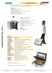
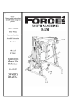
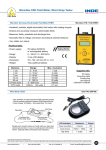
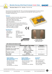
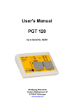
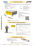
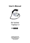
SRM®200 reliable & caring since 1976 Pocket size surface resistance meter with LCD display. Includes conductive carrying case, grounding cord, USB-Cable, calibration certificate and software for reading the saved test data. • Test range:103 - 1012 ohm • Test voltage: open circuit voltage 100 V (switches automatically above 1 MOhm) •O peration: Battery operated •D isplay: LCD-Display •P robes: Built-in electrodes with conductive rubber Built-in bar electrodes Part Nr. 7100.SRM200.K Surface Resistance Meter SRM® 200 SRM®200/EFM®51 STARTERKIT Starterkit for testing conductive an dissipative surfaces and electrostatic fields/surface potentials Includes • SRM®200 as described above • EFM®51 (see page 79) • conductive carrying case Part Nr. 7100.SRM200.SK51 SRM®200/EFM®51 Startertkit TEST AND MEASUREMENT • with memory and USB connection to PC • 2 external probes connection possible Warmbier ESD Field Meter, Wrist Strap Tester reliable & caring since 1976 ESD Safe Warmbier P/N: 7100.EFM51 Warmbier Germany, Electrostatic Field Meter EFM51 • Handheld, • Detects portable, digital electrostatic field meter with rotating chopper and accurately measures electrostatic fields • Measures: fields, potentials and discharge time • Automatic field to voltage conversion according to selected distance • Very stable zero adjust Technical data: • Power supply: • Range: • Display: • Dimension: • Weight: Distance: 1 cm 2 cm 5 cm 10 cm 20 cm E-Field mode CPS mode 9V battery IEC6F22 or rechargeable battery 0 - 160 kV / 0 - 800 kV/m 2 row LCD-display 70 x 122 x 26 mm (W x L x H) 130 g (without battery) Range: 0 - 8 kV 0 - 16 kV 0 - 40 kV 0 - 80 kV 0 - 160 kV 0 - 800 kV/m 1.000 to 100 volts Max. resolution 1 volt 2 volts 10 volts 10 volts 20 volts 100V/m 0,1 sec. Supplied with: 9V battery Grounding cable Carrying bag User Manual Calibration certificate Wrist Strap Tester Inde P/N: ISM-498 • Use anywhere to check personnel ESD grounding quickly • Checks contact resistance between Wrist Strap and skin • Power Supply: 9V Battery • Grounding Wire: 2.5 meter Wrist Strap Operation Grounding Wire of Wrist Strap Tester Grounding Wire of Wrist Strap Simply touch circular surface on Tester with your hand and connect ground wire. In case of a safe ground, LED will be 'Green'. Opposite Table summarizes test indications. LED Indication Resistance Buzzer Power Low (Red) < 750 KΩ OFF Good (Green) 750KΩ ~ 10MΩ ON High (Red) > 10 MΩ OFF shown trademarks are property of their respective owners. While the information contained herein in, has been carefully compiled to the best of our knowledge, nothing is intended as representation and warranty on our part; and no statement shall be construed as recommendation to infringe any of existing patents. We accept no liability of whatsoever for any faults and errors in the information contained herein. Contents of this catalogue and specifications of the products, are subject to change without notice due to continuous improvements. www.indeonline.in Cell: 09316134502 Fax: 0172-4640415 Email: [email protected] 29 Replacing the Battery Replace the 9V battery when “Low Battery” appears on the display. Please switch off the unit before opening the battery compartment. Remove the battery and carefully disconnect the contact-clip. Plug the contact-clip onto the new battery and put it back into the compartment; then close the compartment. Electrostatic Field Meter - EFM 51 V0805 Warning The unit is not approved for usage in explosive areas! The usage in power plants is not allowed! This unit cannot measure alternating fields > 1 Hz! The Instrument must be grounded when high electrostatic charges are present. Sparking on the modular system can cause damage to the unit and need to be avoided. The EFM51 includes: • Electro Field Meter EFM 51 including the 9V battery and 2 cm distance guides • Storage Bag including grounding cable and clip • User’s manual in German and English • Calibration Certificate Legend Small hand-held Electrostatic Field Meter with digital display designed to measure electrostatic charges and fields according to the field mill induction principle. • 1. 2. 3. 4. 5. 6. 7. 8. Rotating chopper LCD – Display (2 x 12) alphanumeric Function/on key Grounding Socket (4mm) Battery compartment (back-side) Zero adjustment trimmer Protection cap Distance guides (removable for E-Field mode) • The instrument measures the electrostatic voltage potential. A microcontroller calculates the field strength (V/m) with the pre-selected distance (1cm, 5cm, 10cm and 20cm). In “E-Field meter” mode, the instrument displays the field strength in “kV/m” Measurement Principle The induced charge caused by the electrical field, generates a current proportional to the electrical field strength. The selective, parametric operating-amplifier measures the current without affecting the averaged time. There are no radioactive components inside the unit. Technical Data Dimensions: Weight: Power Supply: Measurement Range: Display: Operating Time: Adjustment: 70 x 122 x 26 mm ( B x L x H ) 130 g (without battery) 9V – Alkaline battery IEC 6F22 or rechargeable NiMH battery distance 1 cm ÿ 0..... 8 kV max. resolution 1 V Distance 2 cm ÿ 0..... 16 kV max. resolution 2 V Distance 5 cm ÿ 0..... 40 kV max. resolution 10 V Distance 10 cm ÿ 0... 80 kV max. resolution 10 V Distance 20 cm ÿ 0... 160 kV max. resolution 20 V E-Field meter ÿ 0… 800 kV/m max. resolution 0,1 kV/m 2 lines, 12 digits alphanumeric LCD display app. 10 hours at continuous operation with an Alkaline battery Within a plate capacitor’s homogeneous field, plate size 200 mm x 200 mm, distance between both plates is 20 mm, the rotating chopper system is centered in the grounded plate. Warranty We provide12 months limited warranty. The warranty does not include the battery, mechanical damage or unauthorized opening of the instrument. Distance guides The instrument is supplied with two 2cm distance guides which are fitted on the front plate. The alphanumeric Liquid Crystal Display (LCD) consists of 2 lines of 12 digits each. The measured distance in cm or the measuring mode is displayed in the first line, while the test result is displayed in the second line. An „overflow !“ indication requires to increase the distance. Operating instructions Operation • Press the „function/on“ key “shortly” to switch on the instrument • Press the key twice while in measuring mode to switch off the instrument • Remove the protection cap before a measurement • The unit will switch off automatically when the „function/on“ key was not pressed for app. 4 minutes (in CPS-Mode app. 18 min.) Hold Function The hold-function freezes the display with the actual measured value. • Press the „function/on“ key “shortly” while in measuring mode for “hold”. • Press the key while in “hold” to return to measuring mode. Measuring Ranges 1. Measurement of electrostatic voltages: The instrument is preset to 2cm distance after switching on. To measure, it must be positioned at 2 cm distance in front of the object. For high voltages or uneven surfaces the measuring distance should be increased. 2. E-Field meter mode The instrument indicates the field strength in V/m for the current position. Measuring Distance / Measuring mode Press and hold the „function/on“-key (approximately 2 seconds) until „change cm“ will appear. The preselected distance in cm is displayed in the first line. Pressing the „function/on“-key changes the measuring distance. 2cm => 5cm => 10cm => 20cm => E-Field meter => CPS-Mode => 1cm After selecting the desired distance or mode, the instrument switches back to measuring mode if no key is pressed for a certain time. Important! The measuring range is preset to 2cm distance each time the instrument is switched on! The instrument measures the field strength in V/m and calculates the voltage using the selected range: Display value (V) = Field strength (V/m) x Distance (m) i.e.. Display value= 1000V Distance= 10cm ÿ 1000V = 10000 V/m x 0,1m In “E-Field meter” mode the instrument displays the field strength in “kV/m”. Battery control The EFM 51 has a permanent battery-voltage-control. If the battery voltage falls below 7,5 V a „Low Battery“ warning appears and the 9V Battery must be replaced! In case the battery falls below 7,0 V the instrument switches off with „auto off“ message to avoid total discharge and acid leakage. Note: Please use Alkaline or Lithium 9V Batteries only! If rechargeable batteries are preferred, please use a suitable battery charger for charging the battery separately and follow the manufacturer’s instructions. Grounding The unit must be connected to ground to allow accurate voltage levels and polarity measurements. Use the grounding socket (4) for ground connection. The unit housing is conductive, and the instrument may be grounded through the operator if he is at ground potential. Zero Adjust in general , zero adjustment is not necessary. However the trimmer (6) can be used for zero adjust if the instrument does not indicate U=000 or U=00X when the rotating chopper is shielded by the protection cap. The last digit can be ignored, as it is much lower than the specified tolerance. Maintenance It is very important not to touch any parts of the rotating chopper. The sensor head must be free of dust and humidity. If needed, the rotating chopper be cleaned with alcohol and a lint-free tissue, when switched off. Deforming the rotating chopper will damage the instrument! Warmbier Germany, Digital Surface Resistance Test Kit reliable & caring since 1976 ESD Safe Warmbier Model SRM200, Part No. 7100.SRM200.K+2x850 Digital test kit makes testing all surfaces accurate and simple. Supplied with two 5 lb. weights & foam filled case. Features: • Pocket size, lightweight, auto ranging surface resistance meter • LCD Display and data memory • USB interface to PC • Integrated temperature and humidity sensor • Built -in electrodes with conductive rubber • External probes can be connected • Rechargeable battery operated Specifications • Resistance range: 1x10³ - 1x10¹² 3 9 • Accuracy range: 10 - 10 = 10 % 10 12 - 10 = 25 % 10 • Test Voltage : • Electrodes: • Weight: • Size: 10/100V Two (2) 5lb weights 290 g 145 x 80 x 35 mm Supplied with: ® Instrument SRM 200 Conductive carrying case Battery charger USB-cable 2 x 5 lb. probes (model 850) Grounding cord Probe model 850 Software for Windows on CD User’s manual and calibration certificate Software Back side view shown trademarks are property of their respective owners. While the information contained herein in, has been carefully compiled to the best of our knowledge, nothing is intended as representation and warranty on our part; and no statement shall be construed as recommendation to infringe any of existing patents. We accept no liability of whatsoever for any faults and errors in the information contained herein. Contents of this catalogue and specifications of the products, are subject to change without notice due to continuous improvements. www.indeonline.in Cell: 09316134502 Fax: 0172-4640415 Email: [email protected] 27 User's Manual Surface Resistance Meter SRM®200 Wolfgang Warmbier e.K. Untere Gießwiesen 21 D-78247 Hilzingen www.warmbier.com SRM200 User's Manual Part No. 7100.SRM200 Table of Contents INTRODUCTION ...........................................................................................................................................3 OPERATING INSTRUCTIONS .....................................................................................................................3 Operation Description .......................................................................................................................3 Measuring Surface Resistance.........................................................................................................4 Measuring Resistance to Ground .....................................................................................................4 Other Measurements........................................................................................................................5 TEST VALUES STORAGE ...........................................................................................................................5 FUNCTIONS..................................................................................................................................................5 View results ......................................................................................................................................5 Delete results....................................................................................................................................5 Change Limits...................................................................................................................................5 Folder names....................................................................................................................................6 Timeout.............................................................................................................................................6 Temperature .....................................................................................................................................6 Date ..................................................................................................................................................6 Calibration.........................................................................................................................................6 Language..........................................................................................................................................6 PACKING LIST .............................................................................................................................................7 WARRANTY ..................................................................................................................................................7 NOTICE .........................................................................................................................................................7 MAINTENANCE ............................................................................................................................................7 CALIBRATION ..............................................................................................................................................7 PROBLEM SOLVING ...................................................................................................................................7 REPAIR .........................................................................................................................................................8 WASTE DISPOSAL.......................................................................................................................................8 TECHNICAL DATA .......................................................................................................................................8 SPARE PARTS .............................................................................................................................................8 Page 2 of 8 Edition: November 2009 SRM200 User's Manual Part No. 7100.SRM200 Introduction The SRM110 is a pocket size, lightweight, auto ranging surface resistance tester. Measured values are displayed on an LCD dot matrix module and can be stored in the internal memory. Each measurement includes the current temperature and relative humidity. Built-in electrodes with conductive rubber make good contact with the object under test. IEC compatible electrodes can be externally connected for tests according to IEC 61340-4-1, IEC 613402-3 and IEC 61340-4-5. The measuring voltage is auto-ranging from 10V to 100V. Operating Instructions Operation Description 1. Socket for external probes 2. LCD-Display 3. Range LED's LED Measuring range 3 4 Green < 1x10 Ω - 9x10 Ω 5 10 Yellow 1x10 Ω - 9x10 Ω 11 Red ≥ 1x 10 Ω Definition Electrostatic conductive Electrostatic dissipative Electrostatic insulating 4. Buttons Up / Down / MENU / OK Button Function MENU - Open menu - Return from sub-menu - Confirm or change value OK - Increase value - Scroll down in menu - Decrease value - Scroll up in menu Simultaneously pressing ▲▼ turns the instrument off. ▼ ▲ 5. "Push to test" button to switch ON and start measurement 6. USB connector for battery charger and PC connection Menu structure overview View results Delete results Delete all data Limit Folder name Timeout Temperature Date Calibration Language Page 3 of 8 Display measurement results Delete measurement data Delete all measurement data Display or change limit values (max. 19) Display or change folder names (max. 99) Folder names can be entered more convenient by using the PC software Turn-off delay time Change temperature between °C and °F Adjust date and time Display calibration date and software version Language selection German / English Edition: November 2009 SRM200 User's Manual Part No. 7100.SRM200 LCD display overview Measured value (V) View result mode active (D) Delete mode active Assigned limit Value exceeds selected limit Value is below selected limit Relative humidity Temperature Storage folder Date Time Battery status Measuring Surface Resistance • • • To measure the surface resistance of an object, hold the instrument onto the surface and press the "PUSH TO TEST" button. The value is indicated on the display. The coloured LED's additionally indicate the measuring range if no limit is assigned. If the limit is assigned, the limit arrows on the display will indicate the measured value being below or above the limit range. ▼▲ selects the storage folder; OK stores the current measurement value to the selected folder. PUSH TO TEST Measuring Resistance to Ground • • • Plug in the supplied grounding cord at one socket of the instrument. The associated internal electrode will be disconnected. Connect the opposite end of the grounding cord to "ground" or a "groundable point". Hold the instrument onto the surface like described above and press the button. PUSH TO TEST Page 4 of 8 Edition: November 2009 SRM200 User's Manual Part No. 7100.SRM200 Other Measurements By connecting external electrodes to the instrument's sockets it is possible to measure "point to point resistance", or "volume resistance" for example. Metal counter electrode Volume resistance RV Probe model 850 Probe model 850 Surface resistance RPP Test values Storage The included software can be used to transfer and process test values to the computer. The functionality includes: Measurement data transfer Store and export measurement data Print measurement report Limit value definition Labelling of measurement folders Adjust Date and time Functions The following functions are available. Most of them can be accessed more conveniently by the PC software. View results MENU - press button View results - select OK - confirm ▼▲ - select folder (1-99) OK - confirm folder ▼▲ - select record (1-99) OK - display value Folder Record Date Time Delete results MENU - press button Delete results - select OK - confirm ▼▲ - select folder (1-99) OK - confirm folder ▼▲ - select record (1-99) OK - confirm to delete ▼▲ - select yes OK - delete value MENU - back to menu Change Limits MENU - press button Limit - select limit OK - select limit (1-19) ▼ - down to name OK - enter name for limit Page 5 of 8 Edition: November 2009 SRM200 User's Manual Part No. 7100.SRM200 ▼ - down to values OK - change values ▼▲ - increase/decrease OK - next value MENU - back to limit MENU - back to menu Folder names MENU - press button Folder Name - select ▼▲ - select folder to change OK - enter text ▼▲ - select character OK - insert character MENU - back to folder names MENU - back to menu Timeout MENU - press button Timeout - select timeout OK - change value MENU - back to menu Temperature MENU - press button Temperature - select temperature OK - change between °C or °F MENU Z- back to menu Date MENU - press button Date - select date OK - change date ▼▲ - increase/decrease value OK - accept value MENU - back to menu Calibration Calibration date and software version display MENU - press button Calibration - select calibration OK - display MENU - back to menu Language MENU - press button Language - select language OK - change language MENU Z- back to menu Page 6 of 8 Edition: November 2009 SRM200 User's Manual Part No. 7100.SRM200 Additional user instructions for the Software are available on the CD-ROM. Packing List The SRM200 includes: 1. 2. 3. 4. 5. 6. 7. 8. ® Surface Resistance Meter SRM 200 Carrying bag Battery charger USB data cable Software on CD-ROM Grounding cord User's manual (German / English) Calibration certificate Warranty The warranty does not include the rechargeable battery, battery damage due to drainage, and mechanical damage of the instrument. The warranty is void if the unit is opened. Notice This instrument is not approved for measurements in explosion hazard areas! High electrostatic charges or measuring insulating highly charged materials might damage the instrument! Using the instrument in power plants is not permitted. Maintenance Battery condition is permanently monitored in the LCD display. Connect the instrument to a computer or use the power supply to charge the battery in time. The unit won't switch on if the battery is damaged. Unscrew the battery lid at the backside of the unit to replace the battery. Replace only a rechargeable battery of the same type and take care of the polarity. Calibration The recommended calibration interval is 2 years. Problem Solving Problem No Operation Cause Battery discharged No operation even after charging Battery defect No operation after battery Wrong polarity replacement, red LED inside the battery case lit Conductive rubber defect Wear Page 7 of 8 Remedy Connect power supply to charge the battery Replace battery Insert battery in correct polarity Replace contact rubber Edition: November 2009 SRM200 User's Manual Part No. 7100.SRM200 Repair Repairs shall be carried out by qualified personnel only. In case you send the instrument for repair, please pack it safely and state clearly the problem Waste Disposal Follow the local environmental rules when disposing of the equipment. Technical Data Power supply: Operating conditions: Storing conditions: Connectors: Resistance measuring range: Temperature measuring range: Humidity measuring range: Memory: Test voltage: Dimensions: PC interface: Case: Weight: Measuring range 3 10 Ω 4 10 Ω 5 10 Ω 6 10 Ω 7 10 Ω 8 10 Ω 9 10 Ω 10 10 Ω 11 10 Ω 12 10 Ω Rechargeable Lithium Battery 3,6V 900mAh R6 (AA) Charged via external power supply or USB interface -5 ... +40°C, up to 75% rel. humidity, non condensing -10 ... +50°C, up to 85% rel. h umidity, non condensing 2 banana sockets - short version (15mm) 3 12 1x10 - 1x10 Ω 0 - 50 °C +/- 1°C 10 - 90% r.F. +/- 5% 9801 measuring values 10V / 100V (automatic) 145 x 80 x 35mm (L x B x H) USB 2.0 ABS 290 g Complies with CE Display range 3 3 1x10 - 9x10 4 4 1x10 - 9x10 5 5 1x10 - 9x10 6 6 1x10 - 9x10 7 7 1x10 - 9x10 8 8 1x10 - 9x10 9 9 1x10 - 9x10 10 10 1x10 - 9x10 11 11 1x10 - 9x10 12 1x10 Resolution 1 kΩ 10 kΩ 100 kΩ 1 MΩ 10 MΩ 100 MΩ 1 GΩ 10 GΩ 100 GΩ 1 TΩ Accuracy 10% reading 10% reading 10% reading 10% reading 10% reading 10% reading 10% reading 25% reading 25% reading 25% reading Test Voltage 10V 10V 10V 100V 100V 100V 100V 100V 100V 100V Spare Parts Part number 7100.SRM200.CR 7100.SRM200.BAT 7100.SRM200.NT Page 8 of 8 Description Conductive rubber (Set of 2 pieces) Lithium rechargeable battery Power supply Edition: November 2009