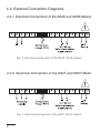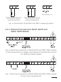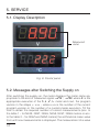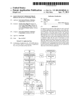
1
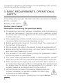
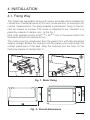
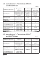
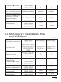
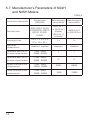
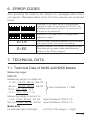
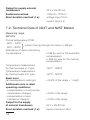
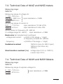
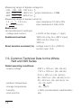
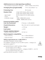
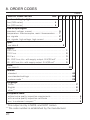
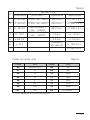
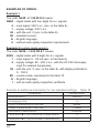
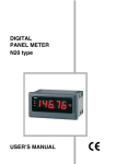
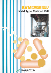
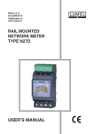
DIGITAL PANEL METER N24 AND N25 METER SERIES USER’S MANUAL 1 2 Contents 1. APPLICATION .............................................................................5 2. METER SET .................................................................................5 3. OPERATIONAL SAFETY ............................................................6 4. INSTALLATION ............................................................................7 4.1 Fixing Way ............................................................................7 4.2 External Connection Diagrams ..............................................8 5. SERVICE ...................................................................................10 5.1 Display Description .............................................................10 5.2 Messages after Switching the Supply on ............................10 5.3 Meter Configuration by Means of LPCon Program ............11 5.4 Manufacturer’s Parameters of N24S, N25S ........................12 5.5 Manufacturer’s parameters of N24T, N25T ........................12 5.6 Manufacturer’s Parameters of N24Z, N25Z ........................13 5.7 Manufacturer’s Parameters of N24H, N25H .......................14 6. ERROR CODES ........................................................................15 7. TECHNICAL DATA ...................................................................15 7.1 Technical Data of N24S, N25S ...........................................15 7.2 Technical Data of N24T, N25T ...........................................16 7.3 Technical Data of N24Z, N25Z ...........................................17 7.4 Technical Data of N24H, N25H ...........................................17 7.5 Common Technical Data for the Whole N24 and N25 Series .....................................18 8. ORDER CODES ........................................................................20 9. SERVICE AND MAINTENANCE ...............................................23 3 4 1. APPLICATION Meters of the N24 and N25 series are digital instruments destined for the measurement of d.c. voltage or d.c. current: uni or bipolar, temperature through J, K thermocouples, Pt100 resistance thermometers and for the measurement of a.c. voltage and a.c. current. A LED display (4 digits for N24 and 5 digits for N25 meter series) constitutes the readout field. The LPCon program is destined for the configuration of N24 and N25 meter series. One must connect the meter with the PC computer through the PD14 programmer. Following parameters can be reprogrammed: - thresholds of displayed overflows, - precision of the displayed result (decimal point), - measurement averaging time , - counting of indications (individual characteristic), - automatic or manual compensation: cold junction temperature for measurements with thermocouples, or wire resistance for Pt100 measurements (only in N24T and N24S meters). All meters are galvanically separated between the supply, measuring inputs and the programmer input Protection grade from the frontal side: IP65. Meter overall dimensions: 96 x 48 x 64 mm (with terminals). 2. METER SET The set is composed of: – Meter types: N24 or N25 ........................................................... 1 pc – User’s manual ............................................................................ 1 pc – Guarantee card ......................................................................... 1 pc – Clamps to fix in the panel .......................................................... 4 pcs – Seal ............................................................................................ 1 pc When unpacking the meter, please check whether the type and execution code on the data plate correspond to the order. If equipment is 5 incomplete or appears to be damaged, file immediately a claim with the carrier and notify the sender at once. 3. BASIC REQUIREMENTS, OPERATIONAL SAFETY In the safety service scope, the meter meets the requirements of the EN 61010-1 standard. Meaning of the symbol: Caution: risk of hazard. Observations concerning the operational safety · All operations concerning transport, installation, and commissioning as well as maintenance, must be carried out by qualified, skilled personnel, and national regulations for the prevention of accidents must be observed. · The programming of N24 and N25 meter series parameters must be carried out after disconnecting measuring circuits · Before switching the meter on, one must check the correctness of connections to the network. · Do not connect the meter to the network through an autotransformer. · Before removing the meter housing, one must switch the supply off and disconnect measuring circuits. · The removal of the meter housing during the guarantee contract period may cause its cancellation. · The meter fulfills requirements related to electromagnetic compatibility and can be used in the industrial electromagnetic environment · When connecting the supply, one must remember that a switch or a circuit-breaker should be installed in the building. This switch should be located near the device, easy accessible by the operator, and suitably marked as an element switching the meter off. · Non-authorized removal of the housing, inappropriate use, incorrect installation or operation, creates the risk of injury to personnel or meter damage. For more detailed information, please study the User’s Manual. 6 4. INSTALLATION 4.1. Fixing Way The meter has separable strips with screw terminals which enable the connection of external wires of 2.5 mm2 cross-section. In execution for current measurement, the plug enables a permanent fixing to the socket by means of screws. The meter is adapted to be mounted in a panel by means of clamps, acc. to the fig. 1. One must prepare a hole of 92+0,6 45+0,6 mm in the panel which the thickness should not exceed 6 mm. The meter must be introduced from the panel front with disconnected supply voltage. Before the insertion into the panel, one must check the correct placement of the seal. After the insertion into the hole, fix the meter by means of clamps (fig.1). Fig. 1. Meter fixing Fig. 2. Overall dimensions 7 4.2. External Connection Diagrams 4.2.1 Electrical Connections of the N24S and N25S Meters Fig. 3. Electrical connection of the N24S, N25S meters 4.2.2 Electrical Connection of the N24T and N25T Meter Fig. 4. Electrical connection of the N24T, N25T meters 8 Thermocouple J, K Resistance thermometer in a two-wire system and with manual compensation Resistance thermometer in a three-wire system and with automatic compensation Fig. 5. Connections of the N24T and N25 T measuring inputs 4.2.3 Electrical Connections N24Z, N24H and N25Z, N25H Meters Fig. 6. Electrical connections of N24Z, N24H and N25Z, N25H meters for the measurement of voltage (and frequency measurement only for the N24Z and N25Z meters) Fig. 7. Electrical connections of N24Z, N25Z and N24H, N25H meters for the current measurement. 9 5. SERVICE 5.1. Display Description Measured value Fig. 8. Frontal panel 5.2. Messages after Switching the Supply on After switching the supply on, the meter displays the meter name appropriate to the kind of measured signal: N24e, N25E where E is the appropriate execution of the s,t,2,h. meter and next, the program version in the shape r x.xx – where x.xx is the number of the current program version or the number of a custom-made execution. Till the time to obtain the required number of correct measurements (acc. to the table 1 – for N24S, N24T, N24H, N25S, N25T, N25H meters or acc. to the table 2 – for N24Z and N25Z meters) the arithmetical mean value from until now measurements is displayed. The measurement of a value 10 from behind the measuring range causes the setting of the overflow and the beginning of the counting of correct measurements again. The time is set by the manufacturer on 1 sec. Table 1 Averaging time Number of averaged measurements Updating of the value on the display 0,5 s 1s 3s 5s 10 s 15 s 20 s 2 7 20 33 67 100 133 0,5 s 0,5 s 0,5 s 0,5 s 0,5 s 0,5 s 0,5 s Table 2 Averaging time Number of averaged measurements Updating of the value on the display 0,5s 1s 1 2 3s 5s 10s 15s 30s 1 m 2 m 5 m 7 m 12 m 15 m 6 10 20 30 60 100 100 100 100 100 100 0,5s 0,5s 0,5s 0,5s 0,5s 0,5s 0,5s 0,5s 0,5s 0,5s 0,5s 0,5s 9,1s In case of any error occurrence or exceeding of the range value, one of the message described in the section 6 will be displayed. 5.3. Meter Configuration by Means of the LPCon Program The free delivered LPCon program, available on the www.lumel.com.pl page, is destined for the N24 and N25 meter series configuration. The configuration user’s manual for N24 and 25 meters by means of the LPCon program is also available on the www.lumel.com.pl page. The PD14 programmer is required for the configuration. CAUTION! The programming of meter parameters must be carried out when measuring circuits are switched off! 11 5.4. Manufacturer’s Parameters of N24S and N25S Meters Parameter description Decimal point Averaging time Individual characteristic Parameter a of the individual characteristic Parameter b of the individual characteristic Upper overflow of the measurement Lower overflow of the measurement Range/value (N24/N25) Manufacturer’s Manufacturer’s value N24S value N25S 0000, 000.0, 00.00, 0.000/00000, 0000.0, 000.00, 00.000, 0.0000 0.5 s; 1 s; 3 s; 5 s; 10 s; 15 s; 20 s; 00.00 for U,I unipolar; 000.0 for U bipolar; 000.00 for U,I unipolar; 0000.0 for U bipolar; 1s 1s disabled, enabled disabled disabled -1999...9999/ -19999...99999 1 1 0 0 9999 99999 -1999 -19999 -1999...9999/ -19999...99999 -1999...9999/ -19999...99999 -1999...9999/ -19999...99999 5.5. Manufacturer’s Parameters of N24T and N25T Meters Parameter description Decimal point Averaging time Individual characteristic Parameter a of the individual characteristic 12 Table 3 Range/value (N24/N25) Table 4 Manufacturer’s Manufacturer’s value N24T value N25T 0000, 000.0, 00.00, 0000 for J 00000 for J 0.000/00000, 0000.0, and K and K 000.00, 00.000, thermocouples, thermocouples, 0.0000 000.0 for Pt100 0000.0 for Pt100 0.5 s; 1 s; 3 s; 5 s; 1s 1s 10 s; 15 s; 20 s; disabled, enabled disabled disabled -1999...9999/ -19999...99999 1 1 Parameter b of the individual characteristic Automatic compensation of terminal temperature/wire resistance Value of manual compensation: terminal temperature/wire resistance Upper overflow of the measurement Lower overflow of the measurement -1999...9999/ -19999...99999 0 0 disabled, enabled disabled disabled - 20...60°C/0...20 : 40°C/0 : 40°C/0 : 9999 99999 -1999 -19999 -1999...9999/ -19999...99999 -1999...9999/ -19999...99999 5.6. Manufacturer’s Parameters of N24Z and N25Z Meters Parameter description Decimal point Averaging time Individual characteristic Parameter a of the individual characteristic Parameter b of the individual characteristic Upper overflow of the measurement Lower overflow of the measurement Range/value (N24/N25) 0000, 000.0, 00.00, 0.000/00000, 0000.0, 000.00, 00.000, 0.0000 0.5 s; 1 s; 3 s; 5 s; 10 s; 15 s; 30 s; 1 min; 2 min; 5 min; 7 min; 12 min; 15 min Table 5 Manufacturer’s Manufacturer’s value N24Z value N25Z 000.0 for U,f 0.000 for I 0000.0 for U,f 0000.0 for I 1s 1s disabled, enabled disabled disabled -1999...9999/ -19999...99999 1 1 0 0 9999 99999 -1999 -19999 -1999...9999/ -19999...99999 -1999...9999/ -19999...99999 -1999...9999/ -19999...99999 13 5.7. Manufacturer’s Parameters of N24H and N25H Meters Table 6 Parameter description Range/value (N24/N25) Manufacturer’s Manufacturer’s value N24H value N25H 0000, 000.0, 00.00, 0.000/00000, 0000.0, 000.00, 00.000, 0.0000 0000 for U or 00.00 for I bipolar 000.0 for U unipolar 0000.0 for U or 000.00 for I Averaging time 0.5 s; 1 s; 3 s; 5 s; 10 s; 15 s; 20 s; 1s 1s Individual characteristic disabled, enabled disabled disabled Parameter a of the individual characteristic -1999...9999/ -19999...99999 1 1 Parameter b of the individual characteristic -1999...9999/ -19999...99999 0 0 Upper overflow of the measurement -1999...9999/ -19999...99999 9999 99999 Lower overflow of the measurement -1999...9999/ -19999...99999 -1999 -19999 Decimal point 14 6. ERROR CODES After switching the meter to the network on, messages about errors can appear. Messages about errors and their reasons are presented below. , , ErCA ErEE Overflow of the upper value of programmed indication range. In the option with Pt100, this message also signals incorrect connections of the wire to the terminal 4. Overflow of the lower value of programmed indication range. Loss of meter calibration values. In such a case, one must contact the service workshop. Incorrect values in the meter configuration data. One must set up again meter parameters by means of the LPCon program. 7. TECHNICAL DATA 7.1. Technical Data of N24S and N25S Meters Measuring range: INPUTS: Measuring range of voltage Un: -11 mV...-10 mV...60 mV...66 mV - 66 mV...- 60 mV...60 mV...66 mV -0.5 V...0 V...10 V...11 V -11 V...-10 V...10 V...11 V input resistance > 1 MΩ Measuring range of current In: -1 mA...0 mA...20 mA...22 mA input resistance 10 Ω 1% 3.6 mA...4 mA...20 mA...22 mA input resistance 10 Ω 1% Basic error (at manufacturer’s settings): (0.2% of the range + 1 digit) 15 Output for supply external transducers 24 V 5% 30 mA Sustained overload 110% Un, 110% In Short duration overload (1 s): voltage input 10 Un current input 5 In 7.2. Technical Data of N24T and N25T Meters Measuring range: INPUTS: Pomiar temperatury Pt100: - 50°C...150°C - 50°C...400°C current flowing through the sensor < 300 PA Resistance of wires connecting the resistance: x 5 : by wire for the automatic compensation x 10 : by wire for the manual compensation Temperature measurement by thermocouple of J type: Temperature measurement by thermocouple of K type: - 50°C...1370°C Basic error (at manufacturer’s settings): ± (0.2% of the range + 1 digit) Additional errors in rated operating conditions: - compensation of cold junction temperature changes - compensation of wire resistance changes ± 0.2% of the range Output for the supply of external transducers 24 V ± 5% 30 mA Short duration overload (1 s): inputs of sensors: 30 V 16 - 50°C...1200°C ± 0.2% of the range 7.3. Technical Data of N24Z and N25Z meters Measuring range: INPUTS: Measuring range of voltage Un: 1...100...120 V a.c. input resistance > 2 MΩ 2.5...250...300 V a.c. 4...400...600 V a.c. Measuring range of current In: 0.01...1...1,2 A a.c. input resistance 10 mΩ ±10% 0.05...5...6 A a.c. input resistance 2 mΩ ±10% Measurement of frequency 20...500 Hz (in voltage range 24...480 V) input resistance > 2 MΩ Basic error (at manufacturer’s settings): - voltage and current: (0.5% of the range + 1 digit) in frequency interval 20...500 Hz - frequency: (0.02% of the range + 1 digit) Sustained overload 150% Un (only for 400 V input), 120% Un (for other Un), 120% In Short duration overload (1 s) voltage input 2 Un (< 1000 V), current input 10 In 7.4. Technical Data of N24H and N25H Meters Measuring range: INPUTS: Measuring range of unipolar voltage Un: 0...100...110 V d.c. 0...250...275 V d.c. input resistance > 2 M: 17 Measuring range of bipolar voltage Un: -120...-100...100...120 V d.c. - 300...- 250...250...300 V d.c. input resistance > 2 M: - 600...- 400...400...600 V d.c. Measuring range of bipolar current In: -1.2...-1...1...1.2 A d.c. input resistance 10 mΩ ±10% - 6...- 5...5...6 A d.c. input resistance 2 mΩ ±10% Basic error (at manufacturer’s settings): - voltage and current: ± (0.2% of the range + 1 digit) Sustained overload: 150% Un (only for ± 400 V input), 120% Un (for other Un), 120% In Short duration overload (1s) voltage input 2 Un (<1000 V) current input 10 In 7.5. Common Technical Data for the Whole N24 and N25 Series Rated operating conditions: - supply voltage 230 V ± 10% a.c. (45...65 Hz) 110 V ± 10% a.c. (45...65 Hz) 24 V ± 10% a.c. (45...65 Hz) 85...253 V a.c. (45...65 Hz) or d.c. 20...40 V a.c. (45...65 Hz) or d.c. - ambient temperature -10...23...55°C - storage temperature - 25...+85°C - humidity - work position < 95% (condensation inadmissible) any 18 Additional errors in rated operating conditions: - from ambient temperature changes (50% of basic error/10 K) Averaging time (programmable) 0.5 s (by default 1 s) Preheating time 30 minutes Readout field: - digit height - colour - indication range: 4-digit LED display (N24 series) 5-digit LED display (N25 series) 20 mm (N24)/14 mm (N25 series) red -1999...9999 (N24 series) -19999...99999 (N25 series) Ensured protection grade from the frontal side: IP 65 acc. to EN 60529 Overall dimensions: 96 x 48 x 64 mm (with terminals) Weight: < 0.25 kg Input power < 6 VA Galvanic isolation between: - supply-measuring input 3.2 kV d.c. Electromagnetic compatibility: - noise immunity acc. to EN 61000-6-2 - noise emission acc. to EN 61000-6-4 Safety requirements acc. to EN 61010-1: isolation between circuits: basic, installation category III (for the 400 V option – category II), pollution grade: 2, maximal phase-to-earth working voltage: - for the supply circuit: 300 V, - for the measuring input 600 V – category II (300 V – cat. III) - for the programming input: 50 V altitude above sea level: < 2000 m, 19 8. ORDER CODES Table 7 DIGITAL PANEL METER N2X X- X X XX XX X X Number of display digits: four (N24 series) .................................................. 4 five (N25 series) ................................................... 5 Kind of input signal: standard: voltage, current ................................... ........ S temperature: thermocouples, resist. thermometers ..... T a.c. signals .......................................................... ........ Z d.c. signals: high voltage, high current ....................... H Input: see table 8 .......................................................... ........ ..... X Supply: 230 V a.c. ..................................................................... ..... ..... 1 110 V a.c. ..................................................................... ..... ..... 2 24 V a.c. ....................................................................... ..... ..... 3 85...253 V a.c./d.c. with supply output: 24 V/30 mA* .............. 4 20...40 V a.c./d.c. with supply output: 24 V/30 mA* ................ 5 Units: see table 9 .................................................................. ..... ..... ..... XX Version: standard ..................................................................... ..... ..... ..... ..... 00 non-standard settings ........................................ ........ ..... ..... ..... ..... NS custom-made **.................................................. ........ ..... ..... ..... ..... XX Language: Polish .......................................................................... ..... ..... ..... ..... ..... P English ........................................................................ ..... ..... ..... ..... ..... E other** ................................................................ ........ ..... ..... ..... ..... ..... X Acceptance tests: without extra quality inspection requirements ... ........ ..... ..... ..... ..... ..... ..... 0 with an extra quality inspection certificate ................. ..... ..... ..... ..... ..... ..... 1 acc. to customer’s request **...................................... ..... ..... ..... ..... ..... ..... X * This output is only in N2XS, and N2XT meters ** The code number is established by the manufacturer 20 Table 8 Item METER TYPE N24S/N25S N24T/N25T N24Z/N25Z N24H/N25H 1 0...20 mA PT100: -50...150°C 100 V a.c. +/- 100 V d.c. 2 4...20 mA PT100: -50...400°C 250 V a.c. +/- 250 V d.c. 3 0...60 mV 400 V a.c. +/- 400 V d.c. 4 0...10 V 1 A a.c. +/- 1 A d.c. 5 ± 60 mV 5 A a.c. +/- 5 A d.c. 6 ± 10 V frequency 20...500 Hz 0...100 V d.c. Thermocouple J: -50 ... 1200°C Thermocouple K: -50 ... 1370°C 7 0...250 V d.c. Codes of printed units Code 00 01 02 03 04 05 06 07 1) Unit without unit o C % A V mV mA kA Table 9 Code 08 09 10 11 12 13 14 XX Unit kV Hz turns rpm bar kPa MPa on order 1) – After agreeing with the manufacturer. 21 EXAMPLES OF ORDER: Example 1 The code: N24Z - 2 1 04 00 E 0 means: N24Z 2 1 04 00 E 0 – digital meter with four digits for a.c. signals, – input signal: 250 V a.c. (acc. to the table 8), – supply voltage: 230 V a.c., – with the unit: V (acc. to the table 9), – standard version, – English language, – without extra quality inspection requirements. Example 2 (custom-made version) The code: N25S - 1 4 02 XX E 1 means: N25S – digital meter with 5 digits for d.c. signals 1 – input signal: 0…20 mA (acc. to the table 8), 4 – supply voltage: 85…253 V a.c., with the 24 V/30 mA supply input for external transducers, 02 – with the unit: % (acc. to the table 9), with display indications: 0…100.0, XX – custom-made, mentioned in the table 10, E – English language, 1 – with an extra quality inspection certificate. Example of additional information for non-standard settings Parameter Decimal point Averaging time Upper measurement overflow Lower measurement overflow Individual characteristic Parameter a of the individual characteristic Parameter b of the individual characteristic 22 Table 10 Range/value 000.00 1s 99999 -19999 enabled 5 0 9. MAINTENANCE AND GUARANTEE The N24 and N25 digital panel meter series do not require any periodical maintenance. In case of some incorrect operations: 1. During the Guarantee Period Defined in the Guarantee Card: One should take the meter down from the installation and return it to the Manufacturer’s Quality Control Dept. If the meter has been used in compliance with the instructions, the Manufacturer warrants to repair it free of charge. 2. After the Guarantee Period: One should turn over the meter to repair it in a certified service workshop. The disassembling of the casing causes the cancellation of the granted guarantee. Our policy is one of continuous improvement and we reserve the right to make changes in design and specifications of any products as engineering advances or necessity requires and revise the above specifications without notice. 23 MEASUREMENT CONTROL RECORDING SALES PROGRAM DIGITAL and BARGRAPH PANEL METERS MEASURING TRANSDUCERS ANALOG PANEL METERS (DIN INSTRUMENTS) INDUSTRIAL PROCESS and POWER CONTROLLERS CHART and PAPERLESS RECORDERS 1-PHASE and 3-PHASE WATT-HOUR METERS LARGE SIZE DISPLAY PANELS ELEMENTS OF INTEGRATION SYSTEMS ACCESSORIES for MEASURING INSTRUMENTS (SHUNTS) CUSTOM-MADE PRODUCTS ACCORDING CUSTOMER’S REQUIREMENTS WE ALSO OFFER OUR SERVICES IN THE PRODUCTION OF: ALUMINIUM ALLOY PRESSURE CASTINGS PRECISION ENGINEERING and THERMOPLASTICS PARTS SUBCONTRACTING of ELECTRONIC DEVICES (SMT) PRESSURE CASTINGS and OTHER TOOLS Lubuskie Zak³ady Aparatów Elektrycznych LUMEL S.A. ul. Sulechowska 1 65-022 Zielona Góra - Poland tel.: (48-68) 329 51 00 (exchange) fax: (48-68) 329 51 01 e-mail: [email protected] http://www.lumel.com.pl 24 Export Department: Tel.: (48-68) 329 53 02 or 53 04 Fax: (48-68) 325 40 91 e-mail: [email protected] N24-09B/01 23.01.2012 QUALITY PROCEDURES: According ISO 9001 and ISO 14001 international requirements. All our instruments have CE mark. For more information, please write to or phone our Export Department.