1
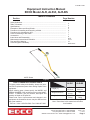
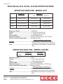
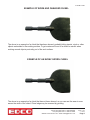
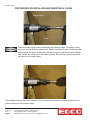
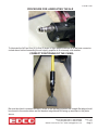
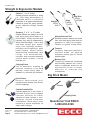
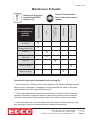
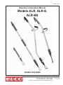
E-ALRE-I-0706
Operator’s Instruction Manual
Models ALR, ALR-E,
ALR-BS
CHISEL SCALERS
100 Thomas Johnson Drive, Frederick, MD 21702-4600 USA
Phone (301) 663-1600 • 1-800-638-3326
Fax (301) 663-1607 • 1-800-447-3326
Website: www.edcoinc.com • Email: [email protected]
Printed in USA
TVW
©2006
Page 1
E-ALRE-I-0706
READ AND UNDERSTAND THE OPERATOR’S INSTRUCTION MANUAL THOROUGHLY
BEFORE ATTEMPTING TO OPERATE THIS EQUIPMENT.
Death or serious injury could occur if this equipment is used improperly.
•
SAFETY MESSAGES
AIR POWERED EQUIPMENT CONTINUED
Safety Instructions are proceeded by a graphic alert symbol
of DANGER, WARNING, or CAUTION.
Indicates an imminent hazard which, if not
avoided, will result in death or serious injury.
• To install or remove chisel: Disconnect the air supply.
Indicates an imminent hazard which, if not
avoided, can result in death or serious injury.
Squeeze the hand lever to release all compressed air.
Pull back in the spring loaded locking collar and hold while
removing the chisel. Hold back on the spring lodaded locking collar while firmly seating the new chisel in the holder.
Release collar to retain the chisel.
• The appropriate accessory must be used for the job at
Indicates hazards which, if not avoided, could
result in serious injury and or damage to the
equipment.
AIR POWERED EQUIPMENT
hand. Do NOT force the tool into the work. The hammering action of the tool will perform the work for you. NEVER
USE THE TOOL AS A PRY BAR. Damage to the equipment will result. If the tool does not seem to perform the
work to your specifications, try another accessory or call
our customer service department at 1-800-638-3326.
• To activate tool, attach the air source, firmly grip the
• When operating this equipment, the operator must
tool and then squeeze the hand lever on the air valve.
wear approved job related safety attire. Eye and hearing
protection must be worn at all times while equipment is
in use as sound levels exceed dBA. Steel toe safety
shoes should be worn. Head protection is required if work
is performed overhead. Wear proper dust mask based on
material being removed.
• After releasing the air valve hand lever,
the tool will continue to operate for up to 15
seconds. This is a normal result of stored
up pressure in the tool casing being released gradually.
Be sure to firmly grip the tool until ALL air leaves the
chamber.
• Use the correct size air hose for the tool, ½” diameter
• Remove the air source from the tool when not in use.
(minimum). Hose and fittings must be rated for safe
handling in excess of 100 PSI pressure. The working
pressure of this tool is 80-90 PSI and should never be
allowed to exceed 100 PSI.
• ALR-E Limit the hose length to 30 feet (10 meters) maximum. Note: The pressure drop of 1/2” diameter hose is
approximately 1 PSI per 90 linear feet.
• ALR-BS Limit the hose length to 30 feet (10 meters)
maximum. Note: The pressure drop of 3/8” diameter hose
is approximately 3 PSI per 90 linear feet.
• A filter/water separator must be provided on the air
source to afford an adequate supply of clean, dry air to
this tool. A lubricator should also be used. If a lubricator is
unavailable, lubricate the tool daily by putting 6 to 7 drops
of lightweight machine oil in the hose connector opening
prior to connecting the air supply. In cold weather, use
graphite oil for lubrication.
• Disconnect the air supply before removing
or installing a chisel or accessory. Squeeze
the hand lever to release all compressed air
from the tool. Use only genuine EDCO chisels and accessories with this equipment. Failure to do so may result in
serious bodily injury or death.
• Replace any damaged parts immediately. Use only
genuine EDCO parts.
Printed in USA
©2006 TVW
Page 2
• This equipment will create dust from the
material being removed. That dust may
contain a chemical known to the state of
California to cause cancer and/or birth defects or other
reproductive harm. Check the chemical properties of the
materials to be removed.
•
It is the operator’s responsibility to
keep other people (workers, pedestrains,
bystanders, etc.) away during operation.
Block off the work area in all directions with roping, safety
netting, etc. for a safe distance. Failure to do so may result
in others being injured by flying debris or exposing them
to harmful dust and noise.
DUST WARNING
Some dust created by power sanding, sawing, grinding,
drilling, and other construction activities contains chemicals
known to cause cancer, birth defects, or other reproductive
harm. Some examples of these chemicals are:
• Lead from lead-based paints, and
• Crystalline silica from bricks, concrete and other
masonry products.
Your risk of exposure to these chemicals varies depending
on how often you do this type of work. To reduce your risk:
work in a well ventilated area, use a dust control system,
such as an industrial-style vacuum, and wear approved
personal safety equipment, such as a dust/particle respirator designed to filter out microscopic particles.
100 Thomas Johnson Drive, Frederick, MD 21702-4600 USA
Phone (301) 663-1600 • 1-800-638-3326
Fax (301) 663-1607 • 1-800-447-3326
Website: www.edcoinc.com • Email: [email protected]
E-ALRE-I-0706
Equipment Instruction Manual
EDCO Model ALR, ALR-E, ALR-BS
Table of Contents
Section
Page Number
Safety Guidelines............................................................................................................
Table of Contents............................................................................................................
Specifications..................................................................................................................
Examples of Worn and Good Chisels.............................................................................
Procedure for Installing and Removing a Chisel.............................................................
Procedure for Lubricating the ALR..................................................................................
Correct Positioning of the Chisel....................................................................................
Accessories....................................................................................................................
Instructions and Disassembly.........................................................................................
Maintenance Instructions & Schedule............................................................................
Dust and Silica Warning..................................................................................................
Limited Equipment Warranty...........................................................................................
2
3
4
5
6
7
7
8
9-10
10-11
12
back cover
L
ALR-E Shown
Figure 1
HOW TO ORDER REPLACEMENT PARTS
To insure product safety and reliability, always use genuine EDCO replacement parts when making repairs to the
equipment.
When ordering parts, please specify the MODEL and
SERIAL NUMBER of the machine as given on the NAMEPLATE. In addition, give part number, description and
quantity as listed on the parts list.
Please note: Due to improvements and changes in the
equipment the illustrations shown may be different from
the actual machine.
Toll Free: Voice 1-800-638-3326 • Fax 1-800-447-3326
Length (L)
Weight Aluminum
Weight Steel
ALR-E
ALR-BS
67.0”
170.2 cm
12.3 lbs.
5.6 kg
17.3 lbs.
7.8 kg
65.5
166.4 cm
n/a
22 lbs.
7.8 kg
Note: Specifications for other models on page 4.
Note: Instructions in this manual are the same
for all models.
100 Thomas Johnson Drive, Frederick, MD 21702-4600 USA
Phone (301) 663-1600 • 1-800-638-3326
Fax (301) 663-1607 • 1-800-447-3326
Website: www.edcoinc.com • Email: [email protected]
Printed in USA
TVW
©2006
Page 3
E-ALRE-I-0706
EDCO Model ALR, ALR-E, ALR-BS SPECIFICATIONS
SPECIFICATIONS FOR - MODEL ALR
WEIGHT*
LENGTH*
Steel
Aluminum
ALR-2
28.5 in (72.4 cm)
8.6 lb (3.9 kg)
7.6 lb (3.4 kg)
ALR-4
49.0 in (124.5 cm)
11.3 lb (5.1 kg)
8.5 lb (3.9 kg)
ALR-5
61.0 in (154.9 cm)
12.9 lb (5.9 kg)
9.0 lb (4.1 kg)
ALR-E
67.0 in (170.2 cm)
17.3 lb (7.8 kg)
12.3 lb (5.6 kg)
* All weight and demensions include the standard 4” (10.2 cm) chisel.
Blows per minute..................................2100-3000
Stroke......................................................1.535 inches (38.99 mm)
Bore.........................................................1.188 inches (30.18 mm)
Air Flow Rate..........................................6-8 CFM @ 90 PSI
Working Pressure.................................80-90 PSI (5.5-6.2 Bar), 100 PSI max
Noise Level During Operation............Exceeds 85 dB(A)
Hearing protection must be worn
Caution....................................................Approximately 15 seconds of pressure
is stored in case after air valve is released
Note..........................................................Specifications are subject to change at any
time.
SPECIFICATIONS FOR - MODEL ALR-BS
ALR-BS
LENGTH
WEIGHT
65.5 in (72.4 cm)
22 lb (9.8 kg)
Blows per minute.................................3500
Stroke.....................................................1.595 inches (40.5 mm)
Bore........................................................1.902 inches (48.3 mm)
Air Flow Rate........................................12-15 CFM @ 90 PSI
Working Pressure...............................80-90 PSI (5.5-6.2 Bar), 100 PSI max
Noise Level During Operation..........Exceeds 92 dB(A)
Hearing protection must be worn
Caution...................................................Approximately 15 seconds of pressure
is stored in case after air valve is released
Note........................................................Specifications are subject to change at any
time.
Printed in USA
©2006 TVW
Page 4
100 Thomas Johnson Drive, Frederick, MD 21702-4600 USA
Phone (301) 663-1600 • 1-800-638-3326
Fax (301) 663-1607 • 1-800-447-3326
Website: www.edcoinc.com • Email: [email protected]
E-ALRE-I-0706
EXAMPLE OF WORN AND DAMAGED CHISEL
The above is an example of a chisel that has been abused, probably hitting inserts, studs or other
objects embedded in the working surface. To get maximum life out of a chisel be careful when
working around objects protruding out of the work surface.
EXAMPLE OF AN EVENLY WORN CHISEL
The above is an example of a chisel that has not been abused, as you can see the wear is even
across the width of the chisel. Chisel edge may be renewed by grinding.
100 Thomas Johnson Drive, Frederick, MD 21702-4600 USA
Phone (301) 663-1600 • 1-800-638-3326
Fax (301) 663-1607 • 1-800-447-3326
Website: www.edcoinc.com • Email: [email protected]
Printed in USA
TVW
©2006
Page 5
E-ALRE-I-0706
PROCEDURE FOR INSTALLING AND REMOVING A CHISEL
Chisel Holder
X
Collar
Remove the air supply before performing the following steps. To install a chisel,
there are several different types but all install in the same manner. Slide the collar
back towards the chisel holder and slide the chisel hex end into the chisel holder
and release the collar to lock the chisel in place. Be sure the chisel is seated all
the way into the chisel holder.
Pictured above shows the chisel installed. To remove a chisel reverse the above procedure and
pull the chisel out of the chisel holder.
Printed in USA
©2006 TVW
Page 6
100 Thomas Johnson Drive, Frederick, MD 21702-4600 USA
Phone (301) 663-1600 • 1-800-638-3326
Fax (301) 663-1607 • 1-800-447-3326
Website: www.edcoinc.com • Email: [email protected]
E-ALRE-I-0706
PROCEDURE FOR LUBRICATING THE ALR
To lubricate the ALR put four (4) to five (5) drops of light weight machine oil in the hose connector
circled above before connecting the air supply, graphite oil in extremely cold weather.
CORRECT POSITIONING OF THE CHISEL
Be sure the chisel is oriented correctly. When in the operating position the straight flat edge should
be closest to the work surface and the beveled edge should be facing up as shown in the photo
above.
100 Thomas Johnson Drive, Frederick, MD 21702-4600 USA
Phone (301) 663-1600 • 1-800-638-3326
Fax (301) 663-1607 • 1-800-447-3326
Website: www.edcoinc.com • Email: [email protected]
Printed in USA
TVW
©2006
Page 7
E-ALRE-I-0706
Straight & Ergonomic Models
Chisels 1”, 2” or 4” widths
General purpose demolition or clean
up. Chip away accumulation of
hardened debris or industrial
deposites, oil & grease absorbances,
ceramic & quarry tile, epoxy mortars,
grouts, refactory cuttings, furnace
slag, etc.
Straight
Model
ALR-5
Scrapers 2”, 4”, 8” or 12” widths
Scraper Blades are made from extra
hard spring steel which fasten to a
milled shank. Easily removed and
replaced, they may be sharpened to
almost knife-like edges. Use to strip
and clean rubber, glue, mastic,
vinyls, floor coverings, ceramics,
insulation and fireproofing, paint
booth buildup, elastic grouts,
waterproofing membranes, tank
linings, rust accumulations,
corrosion and encrusted deposits
around water intakes, roofing
materials, etc.
Ergo
Model
ALR-E
Big Stick
Model
ALR-BS
Shingle Removal Tool
Serrated scraper blades are made
from extra hard spring steel and are
equipped to easily lift shingles.
Fastens to special milled chisel.
Tampers
For posts, tamp grout material in
confined areas, set packing
materials around pipe or flatten
asphalt edges.
Bushing Tool
Forged and tempered, hardened
steel bushing hammer tool. Use to
create a roughened surface for an
architectural finish or better
adhesion of coatings and
overlayments.
Chipping Points
Use for demolition; breaking up
concrete, ceramics or any hard
material; break sharp edge of
sidewalk to eliminate trip hazards.
Big Stick Model
Joint Cleaner
Remove deteriorated joint
compound and sealers from factory
floors or highways.
Carbide Scabbler Bits
Carbide tipped bits in two styles: 5
point and 9 point. Use to roughen
concrete surfaces for better
adhesion of grout, mortars or overlayments around equipment
installations. Break away loose
concrete or mortar droppings on
slabs, walls & ceilings.
Printed in USA
©2006 TVW
Page 8
Scrapers
Chisels
Chipping Point
Questions? Call EDCO
1-800-638-3326
100 Thomas Johnson Drive, Frederick, MD 21702-4600 USA
Phone (301) 663-1600 • 1-800-638-3326
Fax (301) 663-1607 • 1-800-447-3326
Website: www.edcoinc.com • Email: [email protected]
E-ALRE-I-0706
CHISEL SCALER
STRAIGHT
ERGONOMIC
*NOTE:
These items are assemblies.
Refer to illustration #2,
page 10, for breakdown.
TO DISASSEMBLE THE ALR SERIES AND BIG STICK
NOTE: Items (#2), (#12), (#13) and (#18) can be replaced as assemblies.
NOTE: All threaded parts are standard right-hand threads.
1. Place Cylinder Housing (#12) in a vice and clamp on the flat ends.
2. To remove Chisel Holder Chuck (#18), loosen Lock Nut and Capscrew, then unscrew the Chisel Holder from the
Cylinder (#15).
3. Unscrew Cylinder (#15) from Cylinder Housing (#12). Cylinder (#15) contains the Piston (#14). Piston is removed
by gently tapping on the small end and lifting Piston (#14) up and out of Cylinder (#15).
4. Cylinder Housing (#12) is not an operating part and rarely needs to be removed. If an air leak is detected, the “O”
rings (#3) should be replaced.
5. Casing (#5) if damaged, may be unscrewed form the Cylinder Housing (#12) and Valve Assembly (#2). There are
no moving parts in the Casing (#5).
6. To remove the Valve Assembly (#2) simply unthread from the upper end of the Casing (#5).
7. To replace Rubber Hand Grips (#4), remove Air Valve Assembly (#2), moisten grips with water and slide grips to a
comfortable position on Casing (#5).
100 Thomas Johnson Drive, Frederick, MD 21702-4600 USA
Phone (301) 663-1600 • 1-800-638-3326
Fax (301) 663-1607 • 1-800-447-3326
Website: www.edcoinc.com • Email: [email protected]
Printed in USA
TVW
©2006
Page 9
E-ALRE-I-0706
MAINTENANCE INSTRUCTIONS
1. Remove air source and chisel accessory from tool before performing any maintenance.
2. Clean tool daily and keep it clean and lubricated. If a lubricator is provided with the air source, it should be adequate.
If you are unsure or no lubricator is provided, lubricate the tool daily before use by putting 4 to 5 drops of lightweight
machine oil in the hose connector opening. If tool is operated in cold weather (near or below freezing), use a graphite
oil instead of the lightweight machine oil as described above.
3. After every 100 hours of use, flush the tool thoroughly with an environmentally safe, nonflammable and non-caustic
solvent to clean out any oil/gunk bildup in the tool. Oil tool immediately after flushing to prevent corrosion.
4. Replace any damaged parts immediately. Use only genuine EDCO parts.
ILLUSTRATION #2
STEPS TO DISASSEMBLE THE AIR
VALVE BODY ASSEMBLY
ILLUSTRATION (#2):
1. To remove Internal Valve Parts:
E - “O” Ring
D - Compression Spring
C - Valve Stem
B - “O” Ring
first remove the Capping screw (F). Note that the Valve Stem (C) should be replaced if it is worn and loose in Valve
Body (A).
2. The “O” Ring (B) for the VALVE Stem (C) may become unseated due to excess air pressure. Check this item if tool
fails to stop running when valve handle is released.
3. The Valve Lever (H) is held in place by the Rivet (I) and two Washers (J).
The “O” Ring (L) must be in place on Valve Assembly (A) to prevent air leaks when assembly is threaded into Casing (#5) page 9.
NOTE: All “O” Rings should be inspected and replaced if air leakage or damage is detected.
NOTE: Be sure to lubricate all parts with a lightweight machine oil when reassembling the tool.
Printed in USA
©2006 TVW
Page 10
100 Thomas Johnson Drive, Frederick, MD 21702-4600 USA
Phone (301) 663-1600 • 1-800-638-3326
Fax (301) 663-1607 • 1-800-447-3326
Website: www.edcoinc.com • Email: [email protected]
E-ALRE-I-0706
Maintenance Schedule
Visual Inspection of
Entire Tool
X
Check chisel for
damage/uneven wear
X
Lubricate
X
Clean Dust & Dirt
Off of Tool
X
Flush Tool
Every Tool Flush
As Required
Daily
Before Operation
All maintenance to
be performed by
qualified
personnel.
Every 100 Hours
of Operation
Read and follow instructions in the motor owner’s
manual.
Repairs are to be done
by authorized EDCO
Dealers only.
X
X
Check “O” Rings
X
Replace “O” Rings
Operational Keys to good equipment care and long life...
1. Before each use, check and insure all hardware, nuts, bolts and fittings are tight
and not worn or damaged. If damaged or missing hardware is noted, it should be
replaced before the tool is put back into service.
2. Check the maintenance instructions for important information about lubrication
intervals. Remember, equipment used in a dusty environment has more frequent
lubrication requirements than equipment that is not used in a dusty environment.
3. After each days use, the chisel scaler should be cleaned. When cleaning, cover
any openings to prevent contaminants from entering the equipment.
100 Thomas Johnson Drive, Frederick, MD 21702-4600 USA
Phone (301) 663-1600 • 1-800-638-3326
Fax (301) 663-1607 • 1-800-447-3326
Website: www.edcoinc.com • Email: [email protected]
Printed in USA
TVW
©2006
Page 11
E-ALRE-I-0706
Dust and Silica Warning
Grinding/cutting/drilling of masonry, concrete, metal and other materials can
generate dust, mists and fumes containing chemicals known to cause serious
or fatal injury or illness, such as respiratory disease, cancer, birth defects or
other reproductive harm. If you are unfamiliar with the risks associated with
the particular process and/or material being cut or the composition of the tool
being used, review the material safety data sheets and/or consult your employer, the manufacturers/suppliers, governmental agencies such as OSHA
and NIOSH and other sources on hazardous materials. California and some
other authorities, for instance, have published lists of substances known to
cause cancer, reproductive toxicity, or other harmful effects.
Control dust, mist and fumes at the source where possible. In this regard use
good work practices and follow the recommendations of the manufacturers/
suppliers, OSHA/NIOSH, and occupational and trade associations. Water
should be used for dust suppression when wet grinding/cutting/drilling is feasible. When the hazards from inhalation of dust, mists and fumes cannot be
eliminated, the operator and any bystanders should always wear a respirator
approved by NIOSH/MSHA for the material being used.
Grinding/cutting/drilling of masonry, concrete and other materials with silica in
their composition may give off dust or mists containing crystalline silica. Silica
is a basic component of sand, quartz, brick clay, granite and numerous other
minerals and rocks. Repeated and/or substantial inhalation of airborne crystalline silica can cause serious or fatal respiratory diseases, including silicosis. In
addition, California and some other authorities have listed respirable crystalline
silica as a substance known to cause cancer. When grinding/cutting/drilling
such materials, always follow the respiratory precautions mentioned above.
Printed in USA
©2006 TVW
Page 12
100 Thomas Johnson Drive, Frederick, MD 21702-4600 USA
Phone (301) 663-1600 • 1-800-638-3326
Fax (301) 663-1607 • 1-800-447-3326
Website: www.edcoinc.com • Email: [email protected]
E-ALRE-I-0706
Page left blank intentionally
***NOTICE***
READ ALL INSTRUCTIONS BEFORE OPERATING EQUIPMENT
***NOTICE***
100 Thomas Johnson Drive, Frederick, MD 21702-4600 USA
Phone (301) 663-1600 • 1-800-638-3326
Fax (301) 663-1607 • 1-800-447-3326
Website: www.edcoinc.com • Email: [email protected]
Printed in USA
TVW
©2006
Page 13
E-ALRE-I-0706
Page left blank intentionally
***WARNING***
"DO IT RIGHT" OR RISK SEVERE PERSONAL INJURY.
FOLLOW INSTRUCTIONS CAREFULLY
***WARNING***
Printed in USA
©2006 TVW
Page 14
100 Thomas Johnson Drive, Frederick, MD 21702-4600 USA
Phone (301) 663-1600 • 1-800-638-3326
Fax (301) 663-1607 • 1-800-447-3326
Website: www.edcoinc.com • Email: [email protected]
E-ALRE-I-0706
Page left blank intentionally
100 Thomas Johnson Drive, Frederick, MD 21702-4600 USA
Phone (301) 663-1600 • 1-800-638-3326
Fax (301) 663-1607 • 1-800-447-3326
Website: www.edcoinc.com • Email: [email protected]
Printed in USA
TVW
©2006
Page 15
E-ALRE-I-0706
LIMITED EQUIPMENT WARRANTY OF SALE – TERMS & CONDITIONS
Equipment Development Company, Inc. herein referred to as EDCO (Seller) warrants that
each new unit manufactured by EDCO to be free from defects in material and workmanship in
normal use and service for a period of (6) six months (except for the chisel head assembly
on all model ALR’s & ALR-BS, in which case the warranty period shall be 90 days) from
date of shipment to the original retail or equipment rental center owner.
Accessories or equipment furnished and installed on the product by EDCO but manufactured by
others, including, but not limited to engines, motors,electrical components, transmissions etc., shall
carry the accessory manufacturers own warranty.
EDCO will, at its option, repair or replace, at the EDCO factory or at a point designated by
EDCO, any part which shall appear to the satisfaction of EDCO inspection to have been
defective in material or workmanship.
EDCO reserves the right to modify, alter and improve any part or parts
without incurring any obligation to replace any part or parts previously sold without such
modified, altered or improved part or parts.
This warranty is in lieu of and excludes all other warranties, expressed, implied, statutory, or
otherwise created under applicable law including, but not limited to the warranty of merchantability and the warranty of fitness for a particular purpose in no event shall seller or the manufacturer of the product be liable for special, incidental, or consequential damages, including
loss of profits, whether or not caused by or resulting from the negligence of seller and/or the
manufacturer of the product unless specifically provided herein. In addition, this warranty shall
not apply to any products or portions there of which have been subjected to abuse, misuse,
improper installation, maintenance, or operation, electrical failure or abnormal conditions
and to products which have been tampered with, altered, modified, repaired, reworked by
anyone not approved by seller or used in any manner inconsistent with the provisions of the
above or any instructions or specifications provided with or for the product
FORCE MAJEURE
Seller’s obligation hereunder are subject to, and Seller shall not be held responsible for, any
delay or failure to make delivery of all or any part of the Product due to labor difficulties,
fires, casualties, accidents, acts of the elements, acts of God, transportation difficulties,
delays by a common carrier, inability to obtain Product, materials or components or qualified
labor sufficient to timely perform part of or all of the obligations contained in these terms
and conditions, governmental regulations or actions, strikes, damage to or destruction in
whole or part of manufacturing plant, riots, terrorist attacks or incidents, civil commotions,
warlike conditions, flood , tidal waves, typhoon, hurricane, earthquake, lightning, explosion
or any other causes, contingencies or circumstances within or without the United States not
subject to the Seller’s control which prevent or hinder the manufacture or delivery of the
Products or make the fulfillment of these terms and conditions impracticable. In the event
of the occurrence of any of the foregoing, at the option of Seller, Seller shall be excused
from the performance under these Terms and Conditions, or the performance of the Seller
shall be correspondingly extended.
This document sets forth the terms and conditions pursuant to which the purchaser (“Purchaser”) will purchase and Equipment Development Co.Inc. (“Seller”)will sell the products,
accessories, attachments (collectively the Products “) ordered by the Purchaser. These terms
and conditions shall govern and apply to the sale of Seller’s Products to Purchaser, regardless
of any terms and conditions appearing on any purchase order or other forms submitted by
Purchaser to Seller, or the inconsistency of any terms therein and herein.
1. PRICE
All prices set forth on any purchase order or other document are F.O.B. Sellers facility or distribution point, as may be determined by Seller (F.O.B.Point). All prices are exclusive of any and all
taxes, including, but not limited to, excise, sales, use, property or transportation taxes related to the
sale or use of the Products, now or hereafter imposed, together with all penalties and expenses.
Purchaser shall be responsible for collecting and/or paying any and all such taxes, whether or
not they are stated in any invoice for the Products. Unless otherwise specified herein, all prices
are exclusive of inland transportation, freight, insurance and other costs and expenses relating
to the shipment of the Products from the F.O.B. point to Purchaser’s facility. Any prepayment by
Seller of freight insurance and other costs shall be for the account of Purchaser and shall be
repaid to Seller.
Printed in USA
©2006 TVW
Page 16
2. PAYMENT TERMS
Payment terms are as follows. 2% 10 days (to approved and qualified accounts). Net 30 days.
This is a cash discount for invoices paid within 10 days after the invoice date, regardless of
date of receipt of shipment. This is not a trade discount and will not be granted to accounts
that do not adhere to stated terms.
*All past due accounts are subject to a late payment fee of 1.5% per month or a maximum
allowed by law if different, along with the expenses incidental to collection including reasonable attorney’s fees and costs.
*Seller reserves the right to hold shipments against past due accounts.
*Seller reserves the right to alter payment terms.
3. FREIGHT TERMS
All shipments will be made F.O.B. shipping point as designated in these Terms and Conditions, and title shall pass at the F.O.B. point. Delivery to the initial common carrier shall
constitute delivery to the Purchaser. Any claims for loss or damage during shipment are
to be filed with carrier by the Purchaser. Seller will not assume responsibility for the performance of the carrier.
Back orders will be shipped in the most practical fashion with charges consistent with our
freight policy established with the original order. UPS, FED EX, MAIL or shipments by other
couriers are subject to the same terms and conditions as outlined in paragraph #3”Freight
Terms”.
4. DELIVERY, DAMAGES, SHORTAGES
Seller shall use reasonable efforts to attempt to cause the Products to be delivered as provided
for in these Terms & Conditions. Delivery to the initial common carrier shall constitute the delivery
to the Purchaser. Sellers responsibility, in so far as transportation risks are concerned ceases
upon the delivery of the Products in good condition to such carrier at the F.O.B. point and all the
Products shall be shipped at the Purchaser’s risk. Seller shall not be responsible or liable for
any loss of income and/or profits, or incidental, special, consequential damages resulting from
Seller’s delayed performance in shipment and delivery.
5. RETURN OF DEFECTIVE PRODUCTS
Defective or failed material shall be held at the Purchaser’s premises until authorization has
been granted by Seller to return or dispose of Products. Products that are to be returned
for final inspection must be returned Freight Prepaid in the most economical way. Credit
will be issued for material found to be defective upon Seller’s inspection based on prices
at time of purchase.
6. PRODUCTS ORDERED IN ERROR
Products may be returned, provided that claim is made and Seller is notified within 7 days
of receipt of Products, and the Products are in original buyer’s possession not more than
30 days prior to return, subject to Seller’s approval. If Products are accepted for return, they
must be Freight Prepaid and buyer will be charged a minimum of 15% restocking charge,
plus a charge back for outbound freight charges if the original order was shipped prepaid.
Returns are not accepted for any Products that are specifically manufactured to meet the
buyer’s requirement of either specifications or quantity.
AGREEMENTS
These Terms and Conditions constitute the entire agreement between Seller and Purchaser as it
relates to terms and conditions of sale, and supersedes any and all prior oral or written agreements,
correspondence, quotations or understandings heretofore in force between the parties relating to
the subject matter hereof. There are no agreements between Seller and Purchaser with respect
to the Product herein except those specifically set forth in and made part of these terms and
conditions. Any additional terms, conditions and/or prices are rejected by Seller.
These terms and conditions may be modified, cancelled or rescinded only by a written
agreement of both parties executed by their duly authorized agents.
USE ONLY GENUINE EDCO PARTS & ACCESSORIES
For your own safety, the safety of others and the life of your machine.
Equipment Development Company, Inc.
100 Thomas Johnson Drive, Frederick, MD 21702-4600 USA
Phone (301) 663-1600 • 1-800-638-3326
Fax (301) 663-1607 • 1-800-447-3326
Website: www.edcoinc.com • Email: [email protected]