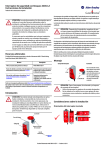
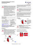
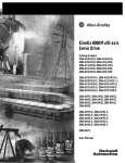
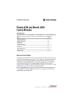
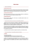
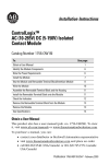
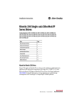
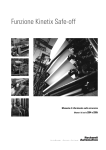
1
Installation Instructions
Kinetix 6200 IAM and AM Power Modules
Catalog Numbers
2094-BC01-MP5-M, 2094-BC01-M01-M,
2094-BC02-M02-M, 2094-BMP5-M, 2094-BM01-M,
2094-BM02-M
Topic
Page
About the Kinetix 6200 IAM and AM Power Modules
1
Important User Information
2
Catalog Number Explanation
3
Before You Begin
3
Setting the Ground Jumper in Ungrounded Power Configurations
4
Install the IAM/AM Power Modules
7
Connector Data
12
Power Wiring Requirements
15
About the Kinetix 6200 IAM and AM Power Modules
The modular Kinetix 6200 drive consists of an integrated axis power module (IAM)
and up to seven axis power modules (AM) each coupled with a control module.
The IAM and AM power modules provide power for up to eight servo motors or
actuators.
Refer to the Kinetix 6200 Modular Multi-axis Servo Drive User Manual, publication
2094-UM002, for detailed information on wiring, applying power, troubleshooting,
and integration with ControlLogix, CompactLogix, or SoftLogix controller platforms.
2
Kinetix 6200 IAM and AM Power Modules
Important User Information
Solid state equipment has operational characteristics differing from those of electromechanical equipment.
Safety Guidelines for the Application, Installation and Maintenance of Solid State Controls (publication
SGI-1.1 available from your local Rockwell Automation sales office or online at
http://literature.rockwellautomation.com) describes some important differences between solid state
equipment and hard-wired electromechanical devices. Because of this difference, and also because of the
wide variety of uses for solid state equipment, all persons responsible for applying this equipment must
satisfy themselves that each intended application of this equipment is acceptable.
In no event will Rockwell Automation, Inc. be responsible or liable for indirect or consequential damages
resulting from the use or application of this equipment.
The examples and diagrams in this manual are included solely for illustrative purposes. Because of the many
variables and requirements associated with any particular installation, Rockwell Automation, Inc. cannot
assume responsibility or liability for actual use based on the examples and diagrams.
No patent liability is assumed by Rockwell Automation, Inc. with respect to use of information, circuits,
equipment, or software described in this manual.
Reproduction of the contents of this manual, in whole or in part, without written permission of Rockwell
Automation, Inc., is prohibited.
Throughout this manual, when necessary, we use notes to make you aware of safety considerations.
WARNING
IMPORTANT
ATTENTION
Identifies information about practices or circumstances that can cause an explosion in
a hazardous environment, which may lead to personal injury or death, property
damage, or economic loss.
Identifies information that is critical for successful application and understanding of
the product.
Identifies information about practices or circumstances that can lead to personal injury
or death, property damage, or economic loss. Attentions help you identify a hazard,
avoid a hazard and recognize the consequences.
SHOCK HAZARD
Labels may be on or inside the equipment, for example, a drive or motor, to alert
people that dangerous voltage may be present.
BURN HAZARD
Labels may be on or inside the equipment, for example, a drive or motor, to alert
people that surfaces may reach dangerous temperatures.
Publication 2094-IN011A-EN-P — July 2009
Kinetix 6200 IAM and AM Power Modules
3
Catalog Number Explanation
This publication applies to the following Kinetix 6200 modular drive components.
IAM/AM Module Catalog Numbers
Integrated Axis Modules (460V)
Cat. No.
Kinetix 6200, IAM, 6 kW converter, 4 A inverter
2094-BC01-MP5-M
Kinetix 6200, IAM, 6 kW converter, 9 A inverter
2094-BC01-M01-M
Kinetix 6200, IAM, 15 kW converter, 15 A inverter
2094-BC02-M02-M
Axis Modules (460V)
Kinetix 6200, AM, 4 A
2094-BMP5-M
Kinetix 6200, AM, 9 A
2094-BM01-M
Kinetix 6200, AM, 15 A
2094-BM02-M
Before You Begin
Remove all packing material, wedges, and braces from within and around the
components. After unpacking, check the item nameplate catalog number against
the purchase order.
Parts List
Drive Component
Ships With
Integrated Axis Module
(IAM)
• Wiring plug connector set for main VAC input power (IPD), control VAC input
power (CPD), contactor enable relay (CED), motor power (MP), and
motor/resistive brake power (BC).
• These installation instructions, publication 2094-IN011.
Axis Module (AM)
• Wiring plug connector set for motor power (MP) and motor/resistive brake
power (BC).
• These installation instructions, publication 2094-IN011.
TIP
Connector kits for user I/O, safety, and auxiliary feedback (catalog number
2090-K6CK-D44M) and motor feedback (catalog number 2090-K6CK-D15M) are
not provided.
Replacement connector sets, as described in the Parts List, are available.
Refer to the Kinetix Motion Control Selection Guide, publication GMC-SG001,
for more information on connector kits and replacement connector sets.
Publication 2094-IN011A-EN-P — July 2009
4
Kinetix 6200 IAM and AM Power Modules
Setting the Ground Jumper in Ungrounded Power
Configurations
Setting the ground jumper is necessary only when using an ungrounded or
high-impedance grounded power configuration. Setting the jumper involves
removing the IAM power module from the power rail, opening the IAM module,
and moving the jumper.
IMPORTANT
If you have grounded power distribution, you do not need to set the ground
jumper. Go to Install the IAM/AM Power Modules on page 7.
Setting the ground jumper is best done when the IAM power module is removed
from the power rail and placed face-up on a solid surface equipped as a grounded
static-safe workstation.
ATTENTION
To avoid personal injury and/or damage to equipment, remove the IAM power
module from the power rail before setting the ground jumper.
By setting the ground jumper for ungrounded power configurations, you no
longer maintain line-to-neutral voltage protection.
To remove the IAM power module from the power rail, refer to the Kinetix 6200
Modular Multi-axis Servo Drive User Manual, publication 2094-UM002.
ATTENTION
This drive contains electrostatic discharge (ESD) sensitive parts and
assemblies. You are required to follow static-control precautions when you
install, test, service, or repair this assembly. If you do not follow ESD control
procedures, components can be damaged. If you are not familiar with static
control procedures, refer to Guarding Against Electrostatic Damage,
publication 8000-4.5.2, or any other applicable ESD awareness handbook.
When using ungrounded input power in common-bus configurations, use this table
to determine where to set the ground jumper.
Ground Jumper to Set
Leader Drive
Follower Drive
Set the Jumper in This Drive
Kinetix 6200 IAM module
Kinetix 6200 IAM module
Leader drive
Kinetix 6200 IAM module
Non-Kinetix 6200 drive
Leader drive
Non-Kinetix 6200 drive
Kinetix 6200 IAM module
Follower drive (if no setting exists
in the leader drive)
Publication 2094-IN011A-EN-P — July 2009
Kinetix 6200 IAM and AM Power Modules
5
Set the Ground Jumper
Follow these steps to set the ground jumper for ungrounded power.
1. Remove the top and bottom front-panel cover screws.
Refer to the figure on page 6 for an illustration of your actual hardware.
2. Pull the front panel cover straight out, as shown, and locate the ground
jumper.
TIP
Access to the jumper improves when the Bulletin 2094 control module
is removed from the IAM power module.
To remove the control module from the IAM power module, refer to the
Kinetix 6200 Modular Multi-axis Servo Drive User Manual, publication
2094-UM002.
3. Move the ground jumper.
Configuration
IAM Power Module
Grounded (default)
Ungrounded
P16 and P17
P18 and P19
2094-BC01-MP5-M (460V)
2094-BC01-M01-M (460V)
2094-BC02-M02-M (460V)
4. Replace the IAM power module front panel cover and two screws.
Apply 1.6 N•m (14 lb•in) torque.
5. Mount the IAM power module back on the power rail.
Refer to Mount the IAM/AM Power Modules on page 9 for help mounting
your IAM module.
Publication 2094-IN011A-EN-P — July 2009
6
Kinetix 6200 IAM and AM Power Modules
Setting the IAM Power Module Ground Jumper (460V)
P16
2094-BC01-MP5-M,
2094-BC01-M01-M, or
2094-BC02-M02-M
IAM (460V) Power Module
Removable Jumper
P17
(behind P18)
Top Screw
P18
P19
Ground jumper set
for grounded configuration
(default setting).
Front Panel Cover
(removed)
Bottom Screw
Ground jumper set for
ungrounded configuration.
P18
P19
IMPORTANT
Use the default jumper setting or remove the jumper entirely for grounded
power configurations. Move the jumper, as shown above, for ungrounded
power.
Publication 2094-IN011A-EN-P — July 2009
Kinetix 6200 IAM and AM Power Modules
7
Install the IAM/AM Power Modules
This procedure assumes you have prepared your panel, mounted your Bulletin
2094 power rail, and understand how to bond your system. For installation
instructions regarding equipment and accessories not included here, refer to the
instructions that came with those products.
SHOCK HAZARD
ATTENTION
To avoid hazard of electrical shock, perform all mounting and wiring of the
Bulletin 2094 power rail and drive modules prior to applying power. Once
power is applied, connector terminals may have voltage present even when not
in use.
Plan the installation of your system so that you can perform all cutting, drilling,
tapping, and welding with the system removed from the enclosure. Because
the system is of the open type construction, be careful to keep any metal debris
from falling into it. Metal debris or other foreign matter can become lodged in
the circuitry, which can result in damage to components.
You can use Bulletin 2094 mounting brackets to mount the power rail or Line
Interface Module (LIM) over the AC line filter. Refer to the 2094 Mounting Brackets
Installation Instructions, publication 2094-IN008, when using mounting brackets
with your Kinetix 6200 drive system.
The Bulletin 2094 power rail comes in lengths to support one IAM module, and up
to seven additional AM modules or up to six additional AM modules and one shunt
module. The connector pins for each slot are covered by a protective boot. The
boot is designed to protect the pins from damage and make sure that no foreign
objects lodge between the pins during installation. Refer to the Kinetix 6000 Power
Rail Installation Instructions, publication 2094-IN003, when installing your power
rail.
ATTENTION
To avoid damage to the power rail during installation, do not remove the
protective boots until the module for each slot is ready for mounting.
Publication 2094-IN011A-EN-P — July 2009
8
Kinetix 6200 IAM and AM Power Modules
Determining Mounting Order
Mount the IAM, AM, shunt, and slot-filler modules in the order (left to right) as
shown. Mount axis modules according to power utilization (highest to lowest) from
left to right starting with the highest power utilization. If power utilization is
unknown, position axis modules (highest to lowest) from left to right based on amp
rating.
Module Mounting Order Example
Highest Power Utilization or Amp Rating
Lowest Power Utilization or Amp Rating
Integrated Axis Module
2094-BC01-MP5-M
IMPORTANT
Axis Module Axis Module Axis Module Axis Module Axis Module Shunt Module Slot Filler Module
2094-BMP5-M 2094-BMP5-M 2094-BMP5-M 2094-BMP5-M 2094-BMP5-M 2094-BSP2
2094-PRF
The IAM power module must be positioned in the leftmost slot of the power
rail. Position your AM power modules, shunt module, and slot-filler modules to
the right of the IAM module.
The shunt module must be installed to the right of the last AM module. Only
slot-filler modules may be installed to the right of the shunt module.
Do not mount the shunt module on power rails with a follower IAM module.
Common-bus follower IAM modules disable the internal, rail mounted, and
external shunt modules.
SHOCK HAZARD
To avoid personal injury due to electrical shock, place a 2094-PRF slot-filler
module in all empty slots on the power rail.
Any power rail connector without a module installed will disable the
Kinetix 6200 system, however, control power will still be present.
Publication 2094-IN011A-EN-P — July 2009
Kinetix 6200 IAM and AM Power Modules
9
Mount the IAM/AM Power Modules
Follow these steps to mount the IAM, AM, shunt, and slot-filler modules.
TIP
All modules mount to the power rail by using the same technique, however,
only the IAM module is shown.
1. Remove the protective boots from the power rail connectors.
IMPORTANT
The IAM module must be positioned in the leftmost slot of the power
rail. Position your axis modules, shunt module, and slot-filler modules
to the right of the IAM module.
2. Determine the next available slot and module for mounting.
3. Remove the label (applied to back and side of module) covering the pins
that mate with the power rail.
4. Inspect power module connector pins and power rail connectors and
remove any foreign objects.
ATTENTION
To avoid damage to the pins located on the back of each IAM, AM,
shunt, and slot-filler module and to make sure that module pins mate
properly with the power rail, hang modules as shown in steps 5…8.
The power rail must be mounted vertically on the panel before hanging
modules on the power rail. Do not mount modules if the power rail is
horizontal.
Publication 2094-IN011A-EN-P — July 2009
10
Kinetix 6200 IAM and AM Power Modules
5. Hang the mounting bracket from the slot on the power rail.
Mounting Bracket
Power Rail Slot
Slots for additional axis modules,
shunt module, or slot-filler modules.
Kinetix 6200 IAM, AM, Shunt,
or Slot-filler Module
(IAM power module is shown)
Power Rail
6. Pivot module downward and align the guide pins on the power rail with the
guide pin holes in the back of the module.
Pivot module downward
and align with guide pins.
Guide Pin
Holes
Guide Pins
Power rail (side view)
in upright vertical position.
Kinetix 6200 Power Module, Rear View
(IAM power module is shown)
TIP
Kinetix 6200 Power Module, Side View
(IAM power module is shown)
The IAM power module has two power rail connectors and guide pins, the AM
module and all other modules have one.
Publication 2094-IN011A-EN-P — July 2009
Kinetix 6200 IAM and AM Power Modules
11
7. Gently push the module against the power rail connectors and into the final
mounting position.
Bracket secured in slot.
Power Rail
Kinetix 6200 IAM, AM, Shunt,
or Slot-filler Module
(IAM power module is shown)
8. Use 2.26 N•m (20 lb•in) torque to tighten the mounting screws.
Bottom front view of
IAM module.
Bottom front view of
AM, shunt,
or slot-filler module
(AM module is shown).
Mounting Screws
9. Repeat steps 1…8 for each AM, shunt, or slot-filler module in your
Kinetix 6200 drive system.
Publication 2094-IN011A-EN-P — July 2009
12
Kinetix 6200 IAM and AM Power Modules
Connector Data
Use these illustrations to identify the IAM and AM power module features and
indicators.
IAM Power Module Features and Indicators
Kinetix 6200
IAM Power Module, Top View
(2094-BC01-MP5-M is shown)
Kinetix 6200
IAM Power Module, Front View
(2094-BC01-MP5-M is shown)
4
DCDC+
L3
L2
L1
CONT ENCONT EN+
W
V
U
MBRK MBRK +
COM
PWR
DBRK DBRK +
1 2 3 4
CTRL 2
CTRL 1
5
1 2 3 4 5 6
1 2
3
1 2 3 4 5 6
2
1 2
1
6
7
8
9
Item
Description
Item
Description
1
Control power (CPD) connector
6
Motor/resistive brake
(BC) connector
2
DC bus/AC input power
(IPD) connector
7
Node address switch
3
Contactor Enable (CED) connector
8
Power-applied indicator
4
Motor cable shield clamp
9
Mounting screw
5
Motor power (MP) connector
ATTENTION
To avoid damage to equipment, do not mount your Bulletin 2094 control module
to the power module when the Power-applied indicator is on. Remove all input
power from the IAM power module before mounting the control module.
Publication 2094-IN011A-EN-P — July 2009
Kinetix 6200 IAM and AM Power Modules
13
AM Power Module Features and Indicators
Kinetix 6200
AM Power Module, Top View
(2094-BMP5-M is shown)
W
V
U
MBRK MBRK +
COM
PWR
DBRK DBRK +
1 2 3 4
1
2
1 2 3 4 5 6
Kinetix 6200
AM Power Module, Front View
(2094-BMP5-M is shown)
3
4
5
Item
Description
1
Motor cable shield clamp
2
Motor power (MP) connector
3
Motor/resistive brake (BC) connector
4
Power-applied indicator
5
Mounting screw
ATTENTION
To avoid damage to equipment, do not mount your Bulletin 2094 control module
to the power module when the Power-applied indicator is on. Remove all input
power from the IAM power module before mounting the control module.
IAM/AM Module Connectors
Designator
Description
Connector
Module
CPD
Control input power (drive)
2-position plug/header
IAM
IPD
VAC input power (drive) and DC bus
6-position plug/header
IAM
CED
Contactor enable
2-position plug/header
IAM
MP
Motor power
4-position plug/header
IAM/AM
BC
Motor/resistive brake
6-position plug/header
IAM/AM
Publication 2094-IN011A-EN-P — July 2009
14
Kinetix 6200 IAM and AM Power Modules
IAM Input Connector Pinouts
Control Power Connector
CPD Pin
Description
1
Signal
CTRL 2
Control power VAC input
2
CTRL 1
DC Bus and Input Power Connector
IPD Pin
Description
Signal
1
DC-
2
An integral, unregulated power supply, consisting of AC line input,
three-phase bridge rectifier, and filter capacitors
3
Chassis ground
4
5
DC+
L3
Three-phase input power
6
L2
L1
Contactor Enable Connector
CED Pin
Description
Signal
1
Relay-driven dry contact used in the safety string for a three-phase
power contactor
CONT EN-
2
CONT EN+
IAM and AM Motor Power and Brake Connector Pinouts
Motor Power Connector
MP Pin
Description
4
Chassis ground
W
3
2
Three-phase motor power
1
IMPORTANT
Signal
V
U
To meet CE requirements, combined motor-power cable length for all axes on
the same DC bus must not exceed 240 m (787 ft) with 460V systems.
Drive-to-motor power cables must not exceed 90 m (295.5 ft).
Publication 2094-IN011A-EN-P — July 2009
Kinetix 6200 IAM and AM Power Modules
15
Motor Brake/Resistive Brake Connector
BC Pin
Description
Signal
6
MBRKMotor brake connections
5
MBRK+
4
Motor brake common
COM
3
+24V brake input power (from LIM module or customer supplied)
PWR
2
DBRKRBM module connections (from RBM module and safety string)
1
DBRK+
Power Wiring Requirements
Wire should be copper with 75 ° C (167 ° F) minimum rating. Phasing of main AC
power is arbitrary and earth ground connection is required for safe and proper
operation.
IMPORTANT
The National Electrical Code and local electrical codes take precedence over
the values and methods provided.
IAM Module Power Wiring Requirements
Terminals
Module
Cat. No.
Description
2094-BC01-Mxx-M
2094-BC02-M02-M
DC bus (1)
and
VAC input
power
IAM
(460V)
Control input
power
2094-BCxx-Mxx-M
Contactor
Enable
(1)
(2)
Pin
IPD-1
IPD-2
IPD-3
IPD-4
IPD-5
IPD-6
Signal
Recommended
Wire Size
mm2 (AWG)
Strip
Length
mm (in.)
Torque Value
N•m (lb•in)
10…2.5
(8…14)
10
(0.38)
1.2…1.5
(10.6…13.2)
DCDC+
L3
L2
L1
CPD-1
CTRL 2
CPD-2
CTRL 1
CED-1
CONT EN-
CED-2
CONT EN+
4…2.5
(12…14)
4…2.5
(12…14) (2)
10
(0.38)
0.5…0.6
(4.4…5.3)
0.5…0.6
(4.4…5.3)
Keep DC common-bus connections (leader IAM to follower IAM module) as short as possible.
The actual gauge of the contactor enable wiring depends on the system configuration. Consult your machine builder, the
NEC, and applicable local codes.
Publication 2094-IN011A-EN-P — July 2009
ATTENTION
To avoid personal injury and/or equipment damage, make sure installation
complies with specifications regarding wire types, conductor sizes, branch
circuit protection, and disconnect devices. The National Electrical Code (NEC)
and local codes outline provisions for safely installing electrical equipment.
To avoid personal injury and/or equipment damage, make sure motor power
connectors are used for connection purposes only. Do not use them to turn the
unit on and off.
To avoid personal injury and/or equipment damage, make sure shielded power
cables are grounded to prevent potentially high voltages on the shield.
IAM/AM Module Power Wiring Requirements
Terminals
Module
IAM or
AM
Cat. No.
2094-BC01-Mxx-M
2094-BC02-M02-M
2094-BMP5-M,
2094-BM01-M,
2094-BM02-M
2094-BCxx-Mxx-M
and
2094-BMxx-M
(460V)
Description
Motor power
Brake power
Pin
Signal
MP-4
MP-3
MP-2
MP-1
W
V
U
BC-6
BC-5
BC-4
BC-3
BC-2
BC-1
MBRKMBRK+
COM
PWR
DBRKDBRK+
Recommended
Wire Size
mm2 (AWG)
Strip
Length
mm (in.)
Torque Value
N•m (lb•in)
Motor power
cable depends
on motor/drive
combination.
10 (0.38)
0.5…0.6
(4.4…5.3)
10 (0.38)
0.22…0.25
(1.9…2.2)
6…1.5
(10…16)
0.75 (18)
Allen-Bradley, CompactLogix, ControlLogix, Kinetix, Rockwell Automation, Rockwell Software, SoftLogix, and TechConnect
are trademarks of Rockwell Automation, Inc.
Trademarks not belonging to Rockwell Automation are property of their respective companies.
Publication 2094-IN011A-EN-P — July 2009
PN-47505
Copyright © 2009 Rockwell Automation, Inc. All rights reserved. Printed in the U.S.A.