1
•
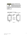
Equipment not used as prescribed within this manual may impair overall safety.
1.0 GENERAL DESCRIPTION
The Net Safety Monitoring Inc. SafeGuard 16 channel Controller is designed to display
and control alarm event switching for up to sixteen detectors (Flame detectors or
transmitters with gas sensor) data points. It may also be set as an eight channel
SafeGuard Controller for applications needing fewer inputs. Alarm features such as ON
and OFF delays, Alarm Acknowledge, and a dedicated horn relay make the SafeGuard
Controller well suited for many multi-point monitoring applications. Data may be input
to the SafeGuard Controller by optional analog inputs or the standard Modbus® RTU
master RS-485 port. A Modbus RTU slave RS-485 port is also standard for sending data
to PC’s, PLC’s, DCS’s, or even other SafeGuard Controllers. Options such as analog I/O
and discrete relays for each alarm are easily added to the addressable I2C bus. Option
boards have 8 channels and therefore require 2 boards for 16 channel applications.
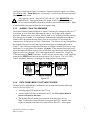
Note: LEL Gas sensors are connected to the SafeGuard Controller via Net Safety
Transmitters. They are NOT connected directly to the SafeGuard Controller at this
time. Perform calibrations of the transmitter/sensor head. Calibrations may
however be performed at the SafeGuard if the transmitter/sensor configuration is in
a location not easily accessible. See Cal Mode.
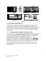
A 240 x 128 pixel graphic LCD readout displays monitored data as bar graphs, trends and
engineering units. System configuration is through user friendly menus and all
configuration data is retained in non-volatile memory during power interruptions. The
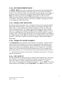
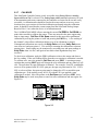
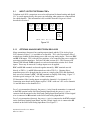
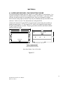
SafeGuard Controller’s front panel is shown below in Figure 1.0 displaying the 8 channel
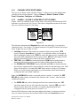
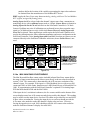
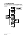
bar graph screen. Additional data screens are shown in Figure 2.0.
ALARM
RESET
Figure1.0
2
SafeGuard Controller User Manual
MAN-0115 Rev 0