1
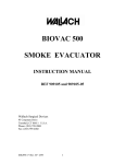
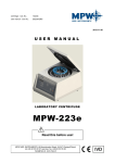
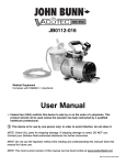
Biovac 13
Operating Instructions
Biovac 13
1
IMPORTANT!
Remove all stabilizing bolts before use!
IMPORTANT!
Remove all stabilizing bolts before use!
Operating environment of instruments
In order to extend the machine’s service life, please pay attention to the following factors which may damage
the machine:
• Environmental Conditions;
• Effects of environment, including natural ultraviolet radiation (ie: Direct Sunlight)
• Erosion and abrasion of the protective cover and other safety parts.
•
•
•
•
•
•
•
•
Indoor use;
Altitude: < 2000m;
Ambient temperature: +5°C~+35°C;
Relative humidity: < 80%;
Operating voltage: 230V, 50 Hz;
Please ensure adequate ventilation in area of use and appropriate sealing measure when performing the
segregation of poisonous substances and pathogenic micro-organism cells;
Ensure there is no vibration and/or a strong draft to influence the performance.
Ensure there is no dust or flammable and corrosive gas present in the ambient air.
Please read this manual carefully when using the instrument for the first time!
The maintenance of the instrument should be carried out by the agents authorized by Biovac.
2
3
The following materials should not be used:
4
•
•
•
•
Flammable and explosive substances;
1
Strong chemical materials;
Toxic or radioactive substances,
Pathogenic microorganisms
7 Speed Bench-top Centrifuge can be maintained only by qualified service engineers using
The Biovac 13 High
appropriate tools.
6
5
Should there be a problem not mentioned in this manual, please contact a Biovac authorized agent for the
correct processing methods.
Please only use accessories provided by Biovac. If other accessories are used, Biovac will not be held
responsible.
The Biovac 13R9 High Speed Refrigeration Bench-top Centrifuge should be checked and maintained regularly.
Safety protection device
8
3
2
1
Biovac 13 High Speed Bench-top Centrifuge has a series of safety protection devices:
➢
➢
➢
4
The machine frame is made of steel plate and the protection steel ring is made of steel casing. The inner
chamber is stainless. The front frame is made of ABS;
The structure of the lid is explosion-resistant. There is a viewport in the center of the lid. Only when
S/F has stopped may the “ “ be pressed to open the lid. Only when the
the centrifuge is on and the rotor
centrifuge lid is locked may you start the centrifuge again.
Overspeed stop: The warning alarm is8sounded
when
6 the
7
4 speed exceeds the preset speed by
5 rotary
200rpm. Wait until the rotor stops completely, then open the lid. Restart when the problem has been
resolved.
Speed/F
Temp.
Time.
Biovac 13
Speed/F
➢
➢
Temp.
Time.
Do Not Open the lidS/Fwhile in operation. If “ “ is pressed by accident while in operation, the device
won’t respond.
Opening in case of emergency:
If7 there6is something
8
4 wrong with the rotor and the electricity is off, you
5
may open the lid by hand when there is no response
when pressing “ “(see “Trouble shooting”).
S/F
Speed/F
Settling the centrifuge
➢
➢
➢
➢
➢
3
2
1
Temp.
8
Time.
7
6
5
4
NOTE: Remove the stabilizing bolts (used during transportation) underneath the unit.
This device should be installed on a rigid table or counter top which is free from vibration and direct
sunlight.
There should be a space of 10 – 15cm around the device for heat emission from the condenser.
After mounting, ensure all four feet are level and supported by the work surface.
Range of operational power supply: AC230V, 50Hz.
You should not disconnect power during the rotor’s operation as this will cause damage to the control circuit.
Configuration
1.2
Transportation and installation
Biovac 13 High Speed Bench-top Centrifuge is transported in a special-purpose wooden case with
protective materials inside to assist with cushioning. After opening, the cushioning should be
removed.
The net weight of the device is about 40kg, therefore it is important to lift the entire device (left and
right) to maintain balance. Do not hold onto the front cover when lifting!
Ensure that balance is maintained with minimal vibration!
Use the special packaging cases when transporting long distance. Handle with care!
1.3
Appropriate working environment
1. Biovac 13R High Speed Bench-top Centrifuge is for indoor use only, where conditions should
meet the following specifications
2. A safety clearance of 10-15cm must be maintained around the centrifuge. When running, there
should be no harmful substances nearby.
3. The work bench should be on a solid floor to avoid vibration; if mobile racks or trolleys are used,
they should be fitted with locking devices to ensure the safe operation of the centrifuge.
4. Should the centrifuge be placed beside a wall or in a corner, there should be 10cm between the
back of the device and the wall as well as 15cm between the left and right sides and the wall to
ensure good ventilation and heat emission.
5. The centrifuge should be placed away from windows to avoid the direct heat and radiation of
sunlight.
6. The centrifuge should always be placed in a clean environment with a constant ambient
temperature between 5°C and 35°C and ambient humidity less than 80%.
Biovac 13
5
1.4
Fixed placement of equipment
After the centrifuge has been placed, it should not be moved frequently. When moving, ensure the
centrifuge is kept upright, balanced and vibration is limited.
To avoid damage to rotor axis, remove the rotor when moving the centrifuge.
1.5
Proper connection of electric supply
The supply socket connected must be earthed securely and be in good condition. The power wires of
the centrifuge should be in accordance with regional safety standards. Voltage and frequency of the
power supply should be in accordance with the requirements stated in the technical description or
specifications labelled on the nameplate of the centrifuge. The power jack/switch is at the back of the
machine indicating “I” for on and “O” for off.
2.
Operating instructions
1. Lid
2. Observation hole
3. Rear Cover
4. Rear Air Port
5. Foot
6. Power Socket / Switch
7. Upper Panel
8. Guy Rope Fastener (for emergency opening)
9. Front Ventilation holes
10. Front Sheild
11. Control Panel and Display Window
6
2.1
Control panel and display interface
1.
2.
3.
4.
5.
6.
7.
Data display window
Adjustable numeric value buttons
Alarm indicator lamp
“Open” button
“Quick run” mode
“Stop” button
“Start” button
Biovac 13
1.
2.
3.
4.
5.
Warning indicators for lid lock and running status. Display area of time: shows remaining running time
Current rotary speed:
displays current and actual rotary speed of the rotor, “rpm”, “00000” for stop;
Current centrifugal force:
displays current and actual centrifugal force (g) of the rotor, “rcf ”, “00000” for stop;
Set indication area of parameter and running status: shows “stand by” when the machine is ready
to work; shows “Running” when the machine runs properly. Shows relevant preset value
when the parameter of temperature, rotary speed and elevating speed curve line is present. Shows failure reasons when warning is displayed.
2.2Starting
Insert one end of the power cable into the supply socket at the bottom right of the back panel, the
other end is connected to the municipal power supply. The voltage of the required power supply is
AC230V at a frequency of 50Hz. After connecting, turn on the power switch at the bottom right
of the back panel, the buzzer will sound and the icon “Heal Force” is displayed and a self-check is
simultaneously carried out. When the self-check has been completed, the main interface appears (see
Fig. 9). The machine is now ready for operation.
2.2Opening
If the electricity is on and the rotor is not running, press the “Open” button on the control panel
to open the lid. The data display window displays “Lift lid”. By spring action, the lid will open
automatically and rise to a certain height. It then needs to be manually lifted to rest on the frame. The inner chamber will now be visible and accessible to the user. The icon on the main interface will
indicate that the lid is “unlocked”.
2.2Closing
Lower the lid and press the lid down until an audible “click” is heard. The lid locks by use of a touch
travel switch. The icon on the main interface will indicate when the lid is properly closed and has
been locked.
When closing the lid, do not press forcefully as you could damage the lid lock!
Biovac 13
7
2.3
Installation of rotor
Inappropriate types of rotors and centrifuge tubes may influence the performance, or even damage
the centrifuge.
Rotors used must be approved by Biovac to avoid malfunction. Various types and specification of
rotors and centrifugal containers are available from Biovac.
Please use the provided allenkey when installing rotors.
Steps to install rotors are as follows (see Fig, 10,11,12):
• Switch the unit on, wait until the self-check is complete;
• Press button 4 to open the lid of the centrifuge, make sure the inner part of the chamber is clean
and clear;
1
• Clean the external surface of the rotor lock sleeve;
2
• Prepare the desired rotor, hold it in both hands, insert the rotor centre into the “lock sleeve”
position, rotate it vertically on the bottom of the cone, then gently press the rotor by hand to
3 in figure 9);
ensure the rotor base is in place as indicated on the display panel5 (No.5 shown
• Use the 5mm allenkey (supplied) and turn it clockwise to fasten the screws (Do Not over tighten);
• Mounting of rotors is now complete.
4
You should periodically recheck that the mounting is secure before and after operation. Tighten the
fastening screws again if necessary to ensure the rotor is mounted firmly.
1
Figure 10: Sketch map of rotor lock sleeve and supporting axis
6
2
5
3
3
4
4
C Temp
o
Info
Time
+00C 00:00:00
0 0 0 0 0 rpm 0 0 0 0
Speed
1
0 0 0 0 0 rcf
o
2
1
Stand By
Figure 11: Sketch map of rotor installation
Figure 10: Sketch map of rotor lock sleeve and supporting axis
6
5
6
Description of figures 10, 11 and 12;
1. Fastening screw
2. Lock sleeve
3. Electrical machine axis (cone)
4. Rubber sheath of the electrical machine
5. Rotor supporting panel of the electrical machine axis
6. Rotor
Figure 12: Sketch map of rotor installed
Figure 11: Sketch map of rotor installation
8
Biovac 13
2.4
Maintenance of lock sleeve and shaft
Steps to maintain lock sleeve and supporting shaft of rotor
• Turn on the unit and wait until the self-check has completed;
• Press button 4 to open the lid of the centrifuge. Unscrew the fastening screw (lock sleeve of the
rotor) with the 5mm allenkey supplied, then clean it. Attention: turn clockwise to tighten and anti-clockwise to loosen;
• Clear dust, impurities and residue away from the centrifugal chamber
• Clean the cone section (see Fig. 11);
• Clean external surface of the lock sleeve of the rotor;
• Screw the fastening bolt into the screw of the cone section SLOWLY with the 5mm hexagon
allenkey. Attention: moderate tightening is permissible. The bolt must not touch the bottom as
this could damage the fastening bolt and cone section and as a result you will be unable to mount
the rotor.
2.5
The calculation of rotor load
Calculation of maximum load capacity:
At high speed, there is enormous centrifugal force; each rotor is designed to safely withstand the force
generated by the maximum rated rotary speed, however, the above “safety factor” is conditional upon
the rotor load not exceeding the maximum rated load.
When separating samples, the total weight must not exceed the maximum rated load of the rotor. Alternately, reduce the weight of samples or calculate permissible running speed to ensure the motor
load will not exceed its maximum rated load.
Calculation method of permissible running speed (Nperm) is as follows:
Nperm=Nmax x (maximum permissible load/actual load)05
Nmax: Maximum rated rotary speed;
Maximum permissible load;
Actual load.
No overloading! The rotor may explode, severely damaging the centrifuge!
2.6
Sample filling
It is critical to ensure the centrifugal container’s (centrifugal tube etc.) specifications are within the
maximum rated acceleration (centrifugal force) specifications; if necessary reduce the acceleration
speed to the recommended specifications of the containers.
During operation it is important to keep the centrifuge balanced. Interference due to the vibration
caused by incorrectly distributed samples should be avoided. Therefore, it is important to evenly fill
the centrifugal container with samples. All samples should be placed in appropriate containers.
Observe the recommended operational life of the centrifugal containers used, especially those
frequently run under maximum permissible load (velocity, temperature). Replace the container
(plastic, glass) immediately if damaged.
Biovac 13
9
Safe use of rotor
Before the rotor runs, load samples and place tubes correctly.
When installing the centrifugal cup of the swing-out rotor, please check that the pins are in the slots
on both sides of the centrifugal cup and whether the four centrifugal cups are movable by hand.
The horizontal rotor is not designed to run for prolonged periods at the critical speed of 2000rpm, as
this may result in major vibration and the working life of the machine will be shortened.
When changing rotors, please unscrew bolts anti-clockwise to loosen the rotor.
Do not start the machine when fastening screws are loose.
When repeated running is required for the centrifuge, re-check the fastening screw after the rotor has
run several times.
It is acceptable to load samples into the centrifugal tubes symmetrically at different times. Asymmetrical loading is strictly forbidden.
Parameter setting
Attention:
You should install the rotor in the rotary shaft before setting parameters.
Note: The setting parameter buttons are touch sensitive and need only be touched lightly.
You may reset the parameters again if mistakes occur in the operation.
Switch on the machine. When initialization has completed press the up and down arrows ( no 2)
on control panel to set desired parameters. The set numerical values cannot be changed while the
centrifuge is running. Press and hold an arrow button for more than 1 second to add or decrease the
preset elevating speed curve line. At the same time, the lowest line on main interface shows an up
and down arrow on the left side and preset elevating speed curve line on the right side. This data will
be stored into the system automatically and the interface will return to its original state after the data
entry is complete.
Setting of rotary speed:
• Rotary speed range of the Biovac 13 High Speed Bench-top Centrifuge:
The minimum rotary speed : 300rpm
The maximum rotary speed: 13,800 rpm.
• Set rotary speed of rotors by following these steps:
First see whether there is a dot in front of the “00000rpm” (as shown in figure 9), if there is no dot,
press the “Speed/F” key to switch between the values and then press up or down arrows (no2) to set
the numerical value. The set numerical values cannot be changed while the centrifuge is running. Press and hold down the relevant arrow (no2) on the “Speed” icon of the control panel (as shown in
figure 4) for more than one second to add or decrease preset rotary speed. simultaneously the bottom
line on the display window shows up and down arrows on the left side and the preset rotary speed on
the right side. This data will be stored into the system automatically and the interface will return to its
original state after the data entry is complete.
Setting the centrifugal force:
It is also possible to change the setting of the rotary speed by setting the numerical value of
“centrifugal force”. Only if you know the type of rotor may you convert the centrifugal force and
rotary speed manually. The value of the centrifugal force and rotary speed are inversely proportionate.
The value of the centrifugal force and rotary speed is displayed synchronously after the centrifuge has
10
Biovac 13
run for several seconds and the model/type of rotor is identified.
Set the centrifugal force as follows:
See whether there is a dot in front of “00000 rcf ” on the main interface (as shown in figure 9), if there
is no dot, press the “Speed/F” button to switch to “00000 rcf ”, and then press the up or down arrow
(no 2) to set numerical value.
Press and hold the up or down arrow (no 2) for more than 1 second to increase or decrease the value.
This data will be stored into the system automatically and the interface will return to its original state
after the data entry is complete.
Attention: A numerical value of centrifugal force set below the minimum rotary speed of 300rpm in
some rotors may lead to the instability of the device!
Calculation on centrifugal force:
Generally speaking, the relative centrifugal force is several thousand times more than G-force (g). It is
the unit to measure the efficiency of various instruments to separate or deposit things. The calculation
of the centrifugal force is related to the centrifugal rational speed and centrifugal radius. The formula
for calculation is as follows:
RCF = 11.18 * (n/1000)2* r
r: Centrifugal radius, unit: cm;
n: Centrifugal speed, unit:rpm (Rpm)
Attention: The numerical value of the maximum centrifugal force is related to the maximum radius. The radius of the rotor and the shape of centrifugal contained is taken into account during the setting
of “The numerical value of the centrifugal force”.
Setting of running time:
Setting range of running time of rotors: 1min ~ 9hr 59min.
Press up or down arrow (no 2) on “Time” icon to adjust the preset numerical value. The set numerical
values cannot be changed while the centrifuge is running. Press and hold the relevant arrow for more
than one second to add or decrease preset running time. Simultaneously the bottom line on main
display shows up and down arrows on the left side and preset time on the right side. This data will
be stored into the system automatically and the interface will return to its original state after the data
entry is complete.
Biovac 13
11
Running of device:
The Run Sequence will not start until the users’ data has been set, the rotor has been installed, the
samples evenly distributed and the lid is closed.
Attention: A lid lock icon on the main interface will indicate whether the lid of the device is closed
correctly.
Temperature control
After temperature setting is complete and the lid is completely closed, the compressor may start at
once to pre-refrigerate. The compressor will stop when the temperature in the chamber reaches a
temperature of +5°C ensuring the temperature of the sample and that in the chamber are the same at
the set speed within 30 minutes after separating starts.
Commencement of Centrifugation
Press the start key no 7 on the control panel and the rotor will begin running evenly at a speed of
300rpm while it will simultaneously run a rotor identification program.
After the rotor has been identified, the rotor accelerates according to the preset elevating speed curve
line of the preset rotary speed;
After pressing the start key (no 7) on the control panel, the run time will begin to count down from
preset time. When it displays zero, that is “00:00”, the centrifuge stops and the work is complete;
The temperature in the chamber falls rapidly from “±00°C”. When the temperature reaches the preset
temperature, the compressor stops;
In operation, the rotary speed and the centrifugal force (see Figure 9) rise independently from
“00000” and “00000” until they reach the preset “Rotary speed” and “Centrifugal force”, and the
centrifugal force is converted automatically according to the detected rotor.
There will be warning prompts if:
The rotary speed and centrifugal force of the rotor exceed the maximum permissible value or preset
value; during a temperature protection operation on the electric machinery; over-voltage operation of
the compressor and if an error occurs with the (EEROM, RAM) and so on.
Warning parameters should be set for each operation.
Do not open the lid while the rotor is running.
Imbalance detection
If the rotor is unbalanced and the vibration of the rotational shaft exceeds the set range during
operation, the device will stop at once and a warning prompt will appear. The problem should be
found and the speed reduced (about 500rpm – 800rpm). The device may be started again once the
problem has been resolved.
Modification of parameter during operation:
All parameters, except the accelerating curve and braking curve, can be modified during operation.
After the parameters have been modified and the main interface menu re-appears, the revised
parameters will come into effect.
12
Biovac 13
Termination of the centrifuge operation:
There are two ways to terminate the centrifuge operation:
During normal operation, the running time has been preset. When the run time has completed, the
centrifuge will stop automatically.
When the rotary speed of the rotor falls to zero, that is “RPM: 00000” and “RCF: 00000”, you may press
the opening button (no 4) on the control panel, then lift the lid to open it. If the state of the lid lock
indicates that the tapered end is open, then you can take the separated samples out of the centrifuge.
During normal operation, you may press “Stop” (no 6) on the control panel any time to terminate the
centrifuge operation, and the centrifuge will stop immediately. The countdown stops at the same time. You can press the open button (no 4) to open the lid only when the “RPM” and “RFC” (centrifugal
force) displayed fall to zero. When the state of the lid lock indicates the tapered end is open you can
take the separated samples out of the centrifuge.
Attention: If the centrifuge is stopped mid-operation, the run time will be cancelled and needs to be
reset before the next centrifuge operation.
Disassembling of rotors
Attention: When disassembling rotors, you should hold and lift the rotors with both hands. Vibration
is forbidden.
Steps to disassemble rotors are as follows:
• Stop the centrifuge;
• Open the lid;
• Take out the centrifugal container first if the horizontal rotor exists;
• Unscrew the fastening screw anti-clockwise with the 5mm allenkey (supplied) for
disassembling,
(no need to completely remove the screw)
• Hold the rotor with both hands and vertically lift it. Vibration is forbidden;
• Remove the container and rotor from the fastening bolt (lock sleeve of the rotor) if the sample
has been contaminated or to prevent it from being contaminated.
• Remove the sample container from the rotor in a suitably safe environment. For example: put
the separated sample, container and rotor in a chest which is safe for biological operations and
open the rotor to remove the sample after being decontaminated.
Description of error messages
The bottom line of the display screen shows all error messages with a [ ] on the left side and the
related error messages on the right side. Simultaneously, a buzzer will sound and a red warning light
will flash.
The sounding alarm will not stop automatically, but it can be silenced by the operator by Pressing the
no 3 button on the control panel. The red warning light will not stop flashing until the problem has
been resolved.
Biovac 13
13
Over max speed
Over set speed
Compressor overheat
Lid opened when run
Lid open failed
Speed sensor error
Temp control failed
12c BUS error
Mainboard reg error
Mainboard ram error
Eprom error
Motor error
Inverter protect
Rotor imbalance
Keyboard reg error
Keyboard ram error
Current rotary speed of rotor exceeds max related rotational speed
Current rotary speed of rotor exceeds the setting speed
Current temperature of the compressor is too high
Lid is opened when the device runs (centrifugal operation)
Lid is not opened correctly
Something wrong with speed sensor
Something wrong with temperature control
12C warning
Mainboard cpu self-check register warning
Mainboard cpu self-check inner ram warning
Something wrong with EPROM
Electrical motor failure
Protection of frequency converter
Imbalance warning
Keyboard cpu self-check register warning
Keyboard cpu self-check inner ram warning
Operation records
Please keep records of each operation (one set for each device) to ensure the normal operation of the
equipment, to prolong the service life and for the accumulation of the operation data of the equipment to
assist in diagnosing the problem or cause of an accident. The recommended table of operation data is as
follows:
Date of Name Weight of
test
of
monotube
sample (including
sample)
Rotor Rotary Time Temp Velocity Program Working
No.
speed
Condition
Operator
Cleaning, Disinfecting and Maintainance
Users have the responsibility to clean and disinfect the centrifuge when dangerous substance spill
in the machine. Users should clean and disinfect it according to the method recommended by the
manufacturers to prevent damage to the machine.
Inappropriate detergents and incorrect cleaning methods may cause damage to the centrifuge or other
internal parts.
Cleaning and sterilization should be carried out according to operating procedures described in the
operating and technical instructions.
Cleaning
14
Biovac 13
Turn off the power switch and unplug from the power source before cleaning!
The centrifuge shell, rotor chamber, rotor, centrifugal containers, etc, should be cleaned and
maintained regularly (or as determined by the service condition), to avoid damage.
If it is unclear which method or process should be followed for cleaning the centrifuge please contact
Biovac.
Organic solvents are forbidden, as they can dissolve the grease in the bearings of the motor;
Liquid, especially organic solvents should not come in contact with the supporting shaft and ball
bearings when cleaning;
If there is frost or a thin layer of ice, it should be wiped away before it has melted.
Disinfecting
Rotors used by this centrifuge can withstand high-pressure sterilization at a Temperature of 127.5°C
and Absolute pressure of 250kPa, maintained for at least 10 mins. Please refer to the cleaning
instructions of separating containers made by other manufacturers.
Confirm whether it is permissible to sterilize rotors and containers with high-pressure before
proceeding. The temperature and duration of the high-pressure sterilization should be strictly
controlled according to the specifications of the different rotors and separating containers in use.
Don’t use the rotor and separating container if they are corroded or damaged.
Maintainance
Don’t pierce the rotor with sharp objects. When being moved and disassembled, you should take care
not to damage the rotor, as scratches and scars may cause cracks during operation.
Regularly check whether there are pits, grooves or minute cracks in the rotor (especially at the base of
the test tube). If any of the above are found, stop using them immediately.
The rotor should be cleaned once a week for normal usage. Rinse the rotor immediately if it is used to
separate saline solution or other corrosive samples. If any of the sample liquids spill onto the rotor, blot
it up and rinse the part immediately.
Please clean with sponges or a cotton cloth dipped in a neutral cleaning solution, then rinse the
cleaning solution off with distilled water. Don’t sprinkle or spray water on the rotor, because it may
cause corrosion on the rotor. Invert the rotor to dry it.
Dust the cooling plates of the condenser once every three months.
Ensure the protective cover is in place.
Inspect rotor parts for any unsafe developments.
Continuity of grounding protection.
Remove the ice or condensation within the Chamber when present.
Turn off the electricity and unplug the supply cable connected to the back of the device before
disassembling the cover casing on the front of the device. Operation is forbidden during maintenance
to avoid an electric shock or damage to the device. Attention: This should be performed only by trained Biovac maintenance personnel!
Only spares provided by Biovac can be used in this device.
Turn off the electricity when the centrifuge isn’t in use.
Biovac 13
15
Transportation and storage
This machine is a precision instrument. Exposure to water, vibration, tilting and inverting the machine is
forbidden in the process of transportation and storage.
Opening the lid in case of emergency
Under normal circumstances, do not manually open the lid when, the electricity is switched off or
the operation to open the lid is non responsive. Attention! Only in the case of an emergency may you
open the lid of the centrifuge by hand to remove samples. When the electricity is switched off, there is
no brake, therefore the rotor will continue to run for a long time. Please wait for it to stop first!
Steps to open the lid in case of emergency are as follows:
• Ensure that the rotors are not running (to confirm, observe from the eye hole at the top of the lid);
• Turn off the electricity;
• Pull out the plastic plug at the bottom of the front wall of the chest with a knife or screwdriver. Pull the line connected to the back of the plastic plug to open the lid, and then remove the separated
samples from the centrifuge;
Return the line into the device and replace the plug to its original place;
P.O. Box 48488, Roosevelt Park, 2129,
South Africa.
Tel: Jhb 011 475 1823
Dbn 031 301 7617
CT 021 461 9607
Fax. 011 475 1819
email: [email protected]
16
Biovac 13